Page 1562 of 2543
FUEL PRESSURE REGULATOR
INSTALLATION
1. INSTALL FUEL PRESSURE REGULATOR
(a) Apply a light coat of gasoline to a new O±ring, and install it
to the pressure regulator.
(b) Attach the pressure regulator to the delivery pipe.
(c) Check that the pressure regulator rotates smoothly.
NOTICE: If it does not rotate smoothly, the O±ring may be
pinched, so remove the pressure regulator and do steps (b)
and (c) above again.
(d) Install the pressure regulator with the 2 bolts.
Torque: 8.8 NVm (90 kgfVcm, 78 in.Vlbf)
2. CONNECT FUEL RETURN PIPE TO FUEL PRESSURE
REGULATOR
Install the return pipe with 2 new gaskets and the union bolt.
Torque: 27 NVm (280 kgfVcm, 20 ftVlbf)
3. CONNECT VACUUM SENSING HOSE TO FUEL
PRESSURE REGULATOR
4. INSTALL THROTTLE BODY
(See throttle body installation)
5. CHECK FOR FUEL LEAKS
(See item 5 in fuel system in precaution) EG±272
± ENGINESFI SYSTEM (2JZ±GTE)
Page 1565 of 2543

INJECTORS REMOVAL
Installation is in the reverse order of removal.
1. REMOVE ENGINE UNDER COVER
2. REMOVE THROTTLE BODY
(See throttle body removal)
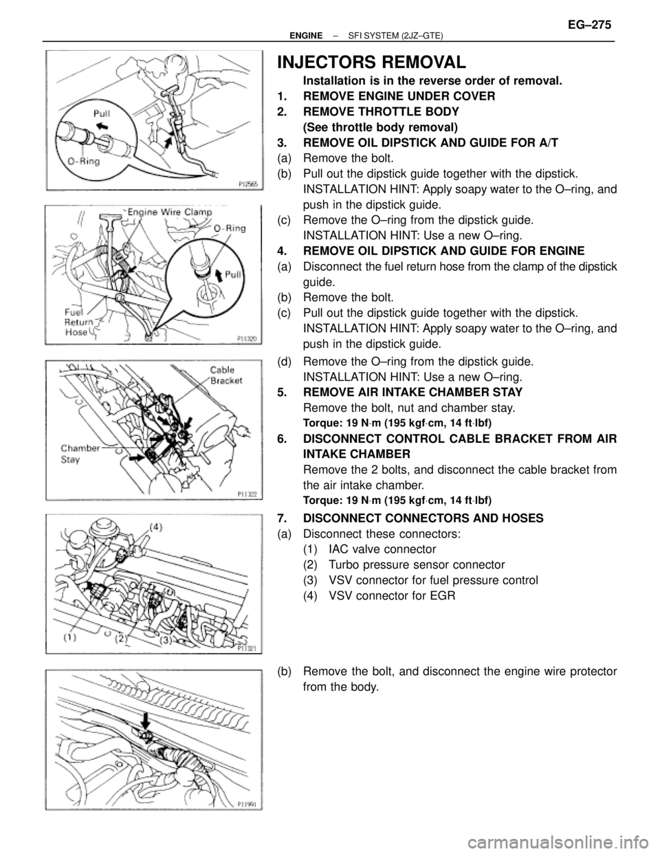
3. REMOVE OIL DIPSTICK AND GUIDE FOR A/T
(a) Remove the bolt.
(b) Pull out the dipstick guide together with the dipstick.
INSTALLATION HINT: Apply soapy water to the O±ring, and
push in the dipstick guide.
(c) Remove the O±ring from the dipstick guide.
INSTALLATION HINT: Use a new O±ring.
4. REMOVE OIL DIPSTICK AND GUIDE FOR ENGINE
(a) Disconnect the fuel return hose from the clamp of the dipstick
guide.
(b) Remove the bolt.
(c) Pull out the dipstick guide together with the dipstick.
INSTALLATION HINT: Apply soapy water to the O±ring, and
push in the dipstick guide.
(d) Remove the O±ring from the dipstick guide.
INSTALLATION HINT: Use a new O±ring.
5. REMOVE AIR INTAKE CHAMBER STAY
Remove the bolt, nut and chamber stay.
Torque: 19 NVm (195 kgfVcm, 14 ftVlbf)
6. DISCONNECT CONTROL CABLE BRACKET FROM AIR
INTAKE CHAMBER
Remove the 2 bolts, and disconnect the cable bracket from
the air intake chamber.
Torque: 19 NVm (195 kgfVcm, 14 ftVlbf)
7. DISCONNECT CONNECTORS AND HOSES
(a) Disconnect these connectors:
(1) IAC valve connector
(2) Turbo pressure sensor connector
(3) VSV connector for fuel pressure control
(4) VSV connector for EGR
(b) Remove the bolt, and disconnect the engine wire protector
from the body.
± ENGINESFI SYSTEM (2JZ±GTE)EG±275
Page 1566 of 2543

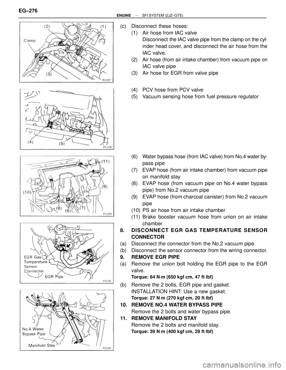
(c) Disconnect these hoses:
(1) Air hose from IAC valve
Disconnect the IAC valve pipe from the clamp on the cyl-
inder head cover, and disconnect the air hose from the
IAC valve.
(2) Air hose (from air intake chamber) from vacuum pipe on
IAC valve pipe
(3) Air hose for EGR from valve pipe
(4) PCV hose from PCV valve
(5) Vacuum sensing hose from fuel pressure regulator
(6) Water bypass hose (from IAC valve) from No.4 water by-
pass pipe
(7) EVAP hose (from air intake chamber) from vacuum pipe
on manifold stay
(8) EVAP hose (from vacuum pipe on No.4 water bypass
pipe) from No.2 vacuum pipe
(9) EVAP hose (from charcoal canister) from No.2 vacuum
pipe
(10) PS air hose from air intake chamber
(11) Brake booster vacuum hose from union on air intake
chamber
8. DISCONNECT EGR GAS TEMPERATURE SENSOR
CONNECTOR
(a) Disconnect the connector from the No.2 vacuum pipe.
(b) Disconnect the sensor connector from the wiring connector.
9. REMOVE EGR PIPE
(a) Remove the union bolt holding the EGR pipe to the EGR
valve.
Torque: 64 NVm (650 kgfVcm, 47 ftVlbf)
(b) Remove the 2 bolts, EGR pipe and gasket.
INSTALLATION HINT: Use a new gasket.
Torque: 27 NVm (270 kgfVcm, 20 ftVlbf)
10. REMOVE NO.4 WATER BYPASS PIPE
Remove the 2 bolts and water bypass pipe.
11. REMOVE MANIFOLD STAY
Remove the 2 bolts and manifold stay.
Torque: 39 NVm (400 kgfVcm, 29 ftVlbf)
EG±276± ENGINESFI SYSTEM (2JZ±GTE)
Page 1567 of 2543

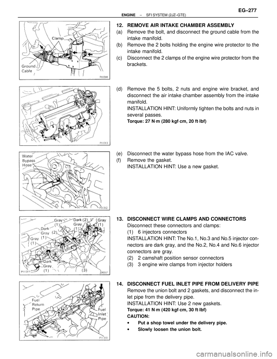
12. REMOVE AIR INTAKE CHAMBER ASSEMBLY
(a) Remove the bolt, and disconnect the ground cable from the
intake manifold.
(b) Remove the 2 bolts holding the engine wire protector to the
intake manifold.
(c) Disconnect the 2 clamps of the engine wire protector from the
brackets.
(d) Remove the 5 bolts, 2 nuts and engine wire bracket, and
disconnect the air intake chamber assembly from the intake
manifold.
INSTALLATION HINT: Uniformly tighten the bolts and nuts in
several passes.
Torque: 27 NVm (280 kgfVcm, 20 ftVlbf)
(e) Disconnect the water bypass hose from the IAC valve.
(f) Remove the gasket.
INSTALLATION HINT: Use a new gasket.
13. DISCONNECT WIRE CLAMPS AND CONNECTORS
Disconnect these connectors and clamps:
(1) 6 injectors connectors
INSTALLATION HINT: The No.1, No.3 and No.5 injector con-
nectors are dark gray, and the No.2, No.4 and No.6 injector
connectors are gray.
(2) 2 camshaft position sensor connectors
(3) 3 engine wire clamps from injector holders
14. DISCONNECT FUEL INLET PIPE FROM DELIVERY PIPE
Remove the union bolt and 2 gaskets, and disconnect the in-
let pipe from the delivery pipe.
INSTALLATION HINT: Use 2 new gaskets.
Torque: 41 NVm (420 kgfVcm, 30 ftVlbf)
CAUTION:
wPut a shop towel under the delivery pipe.
wSlowly loosen the union bolt.
± ENGINESFI SYSTEM (2JZ±GTE)EG±277
Page 1568 of 2543
15. DISCONNECT FUEL RETURN PIPE FROM FUEL
PRESSURE REGULATOR
Remove the union bolt and 2 gaskets, and disconnect the
fuel pipe from the pressure regulator.
INSTALLATION HINT: Use 2 new gaskets.
Torque: 27 NVm (280 kgfVcm, 20 ftVlbf)
CAUTION:
wPut a shop towel under the pressure regulator.
wSlowly loosen the union bolt.
16. REMOVE DELIVERY PIPE AND INJECTORS
(a) Remove the 6 bolts and 3 injector holders.
Torque: 7.8 NVm (80 kgfVcm, 69 in.Vlbf)
(b) Remove the 6 insulators from the injectors.
INSTALLATION HINT: Use 6 new insulators.
(c) Re mo ve th e 2 bo lts, th e de live ry pip e an d 6 in je cto rs
assembly.
Torque: 21 NVm (210 kgfVcm, 15 ftVlbf)
(d) Remove the 2 spacers from the intake manifold. EG±278
± ENGINESFI SYSTEM (2JZ±GTE)
Page 1570 of 2543
(c) Remove the union bolt and 2 gaskets, and disconnect the
fuel inlet hose from the fuel filter outlet.
(d) Connect SST (hose) to the fuel filter outlet with SST (union),
the 2 gaskets and union bolt.
SST 09268±41045 (90405±09015)
Torque: 29 NVm (300 kgfVcm, 22 ftVlbf)
(e) Disconnect the fuel return hose from the fuel return pipe.
(f) Connect the fuel return hose to the fuel outlet of the pressure
regulator on the delivery pipe with SST (union), the 2 gaskets
and union bolt.
SST 09268±41045 (09268±41070) EG±280
± ENGINESFI SYSTEM (2JZ±GTE)
Page 1571 of 2543

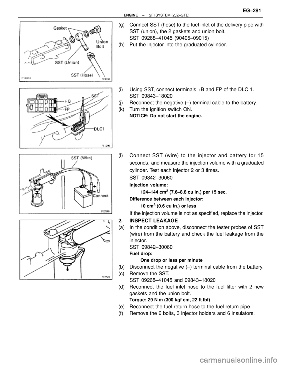
(g) Connect SST (hose) to the fuel inlet of the delivery pipe with
SST (union), the 2 gaskets and union bolt.
SST 09268±41045 (90405±09015)
(h) Put the injector into the graduated cylinder.
(i) Using SST, connect terminals +B and FP of the DLC 1.
SST 09843±18020
(j) Reconnect the negative (±) terminal cable to the battery.
(k) Turn the ignition switch ON.
NOTICE: Do not start the engine.
(l) Connect SST (wire) to the injector and battery for 15
seconds, and measure the injection volume with a graduated
cylinder. Test each injector 2 or 3 times.
SST 09842±30060
Injection volume:
124±144 cm
3 (7.6±8.8 cu in.) per 15 sec.
Difference between each injector:
10 cm
3 (0.6 cu in.) or less
If the injection volume is not as specified, replace the injector.
2. INSPECT LEAKAGE
(a) In the condition above, disconnect the tester probes of SST
(wire) from the battery and check the fuel leakage from the
injector.
SST 09842±30060
Fuel drop:
One drop or less per minute
(b) Disconnect the negative (±) terminal cable from the battery.
(c) Remove the SST.
SST 09268±41045 and 09843±18020
(d) Reconnect the fuel inlet hose to the fuel filter with 2 new
gaskets and the union bolt.
Torque: 29 NVm (300 kgfVcm, 22 ftVlbf)
(e) Reconnect the fuel return hose to the fuel return pipe.
(f) Remove the 6 bolts, 3 injector holders and 6 insulators.
± ENGINESFI SYSTEM (2JZ±GTE)EG±281
Page 1573 of 2543
FUEL PRESSURE PULSATION DAMPER
COMPONENTS FOR REMOVAL AND
INSTALLATION
FUEL PRESSURE PULSATION DAMPER
REMOVAL
1. REMOVE STARTER
(See starter removal in Starting System)
2. REMOVE FUEL PRESSURE PULSATION DAMPER
(a) Remove the pulsation damper and upper gasket.
(b) Disconnect the fuel inlet pipe from the fuel pipe support, and
remove the lower gasket.
FUEL PRESSURE PULSATION DAMPER
INSTALLATION
1. INSTALL FUEL PRESSURE PULSATION DAMPER
(a) Install the fuel inlet pipe and pulsation damper with 2 new
gaskets.
HINT: Different sized gaskets are used for the upper (large
size) and lower (small size).
± ENGINESFI SYSTEM (2JZ±GTE)EG±283