Page 1549 of 2543
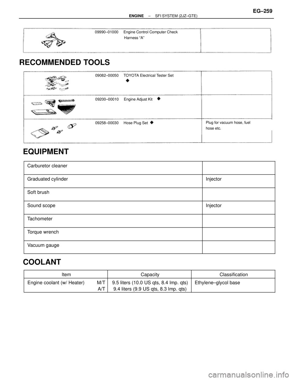
09990±01000Engine Control Computer Check
Harness ªAº
RECOMMENDED TOOLS
09082±00050 TOYOTA Electrical Tester Set
09200±00010Engine Adjust Kit
09258±00030 Hose Plug SetPlug for vacuum hose, fuel
hose etc.
EQUIPMENT
������������������������� �
������������������������ �������������������������Carburetor cleaner
����������� �
���������� �����������
������������������������� �
������������������������ �������������������������Graduated cylinder����������� �
���������� �����������Injector
������������������������� �
������������������������ �������������������������
Soft brush����������� �
���������� �����������
������������������������� �
������������������������ �������������������������
Sound scope����������� �
���������� �����������
Injector
������������������������� �������������������������Tachometer����������� �����������
������������������������� �
������������������������ �������������������������Torque wrench
����������� �
���������� �����������
������������������������� �
������������������������ �������������������������Vacuum gauge����������� �
���������� �����������
COOLANT
������������ ������������Item������������ ������������Capacity������������� �������������Classification������������ �
����������� ������������Engine coolant (w/ Heater) M/T
A/T������������ �
����������� ������������9.5 liters (10.0 US qts, 8.4 lmp. qts)
9.4 liters (9.9 US qts, 8.3 lmp. qts)������������� �
������������ �������������Ethylene±glycol base
± ENGINESFI SYSTEM (2JZ±GTE)EG±259
Page 1581 of 2543
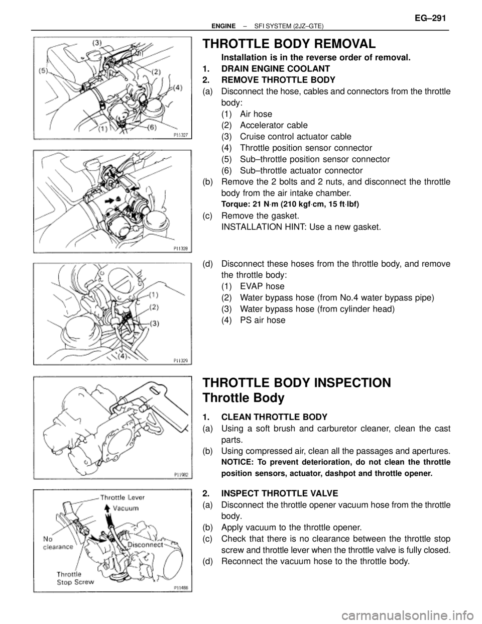
THROTTLE BODY REMOVAL
Installation is in the reverse order of removal.
1. DRAIN ENGINE COOLANT
2. REMOVE THROTTLE BODY
(a) Disconnect the hose, cables and connectors from the throttle
body:
(1) Air hose
(2) Accelerator cable
(3) Cruise control actuator cable
(4) Throttle position sensor connector
(5) Sub±throttle position sensor connector
(6) Sub±throttle actuator connector
(b) Remove the 2 bolts and 2 nuts, and disconnect the throttle
body from the air intake chamber.
Torque: 21 NVm (210 kgfVcm, 15 ftVlbf)
(c) Remove the gasket.
INSTALLATION HINT: Use a new gasket.
(d) Disconnect these hoses from the throttle body, and remove
the throttle body:
(1) EVAP hose
(2) Water bypass hose (from No.4 water bypass pipe)
(3) Water bypass hose (from cylinder head)
(4) PS air hose
THROTTLE BODY INSPECTION
Throttle Body
1. CLEAN THROTTLE BODY
(a) Using a soft brush and carburetor cleaner, clean the cast
parts.
(b) Using compressed air, clean all the passages and apertures.
NOTICE: To prevent deterioration, do not clean the throttle
position sensors, actuator, dashpot and throttle opener.
2. INSPECT THROTTLE VALVE
(a) Disconnect the throttle opener vacuum hose from the throttle
body.
(b) Apply vacuum to the throttle opener.
(c) Check that there is no clearance between the throttle stop
screw and throttle lever when the throttle valve is fully closed.
(d) Reconnect the vacuum hose to the throttle body.
± ENGINESFI SYSTEM (2JZ±GTE)EG±291
Page 1587 of 2543
IAC VALVE REMOVAL
1. DRAIN ENGINE COOLANT
2. DISCONNECT IAC VAVE CONNECTOR
3. REMOVE IAC VALVE
(a) Remove the 2 bolts, and disconnect the IAC valve from the
air intake chamber.
(b) Remove the gasket.
(c) Disconnect these hoses from the IAC valve, and remove the
IAC valve:
(1) Air hose
(2) Water bypass hose (from No.2 water bypass pipe)
(3) Water bypass hose (from No.4 water bypass pipe)
(d) Remove the seal washer and check valve.
IAC VALVE INSPECTION
INSPECT IAC VALVE OPERATION
(a) Apply battery voltage to terminals B1 and B2, and while
repeatedly grounding S1±S2±S3±S4±S 1 in sequence, and
check that the valve moves toward the closed position.
(b) Apply battery voltage to terminals B1 and B2, and while
repeatedly grounding S4±S3±S2±S1±S 4 in sequence,
check that the valve moves toward the open position.
If operation is not as specified, replace the IAC valve.
± ENGINESFI SYSTEM (2JZ±GTE)EG±297
Page 1588 of 2543
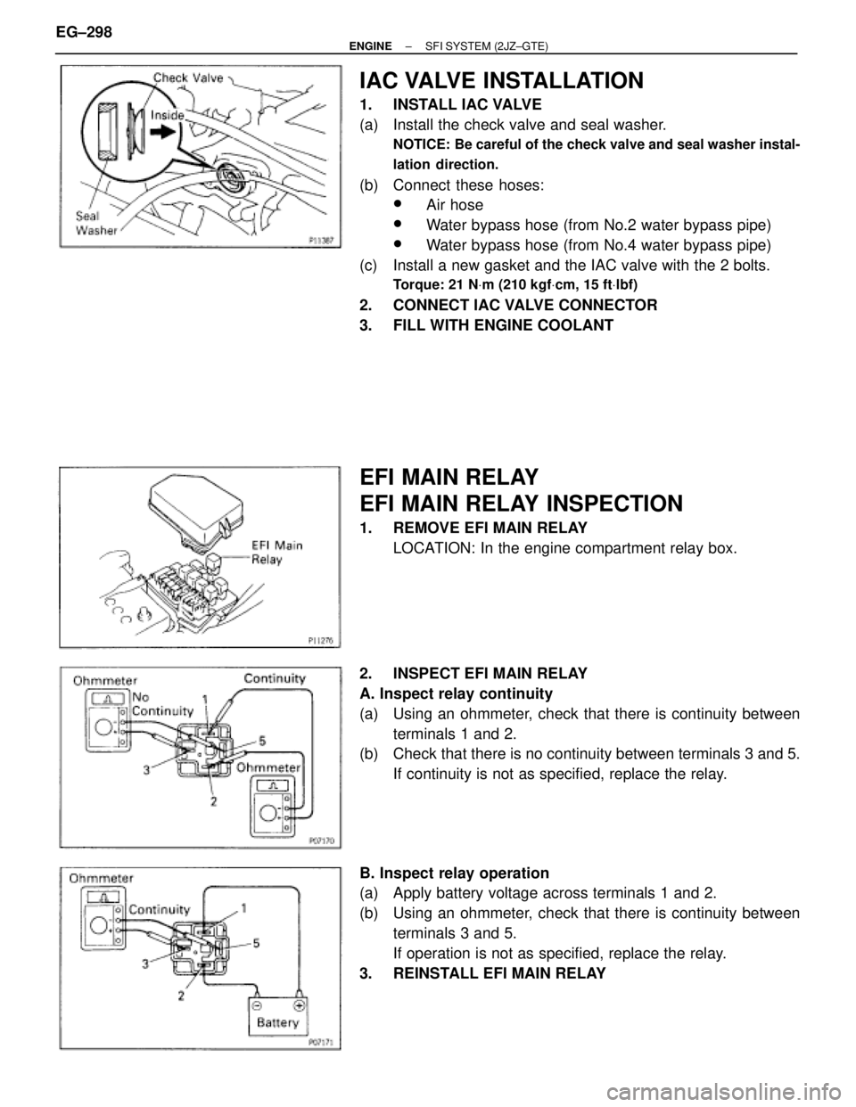
IAC VALVE INSTALLATION
1. INSTALL IAC VALVE
(a) Install the check valve and seal washer.
NOTICE: Be careful of the check valve and seal washer instal-
lation direction.
(b) Connect these hoses:
wAir hose
wWater bypass hose (from No.2 water bypass pipe)
wWater bypass hose (from No.4 water bypass pipe)
(c) Install a new gasket and the IAC valve with the 2 bolts.
Torque: 21 NVm (210 kgfVcm, 15 ftVlbf)
2. CONNECT IAC VALVE CONNECTOR
3. FILL WITH ENGINE COOLANT
EFI MAIN RELAY
EFI MAIN RELAY INSPECTION
1. REMOVE EFI MAIN RELAY
LOCATION: In the engine compartment relay box.
2. INSPECT EFI MAIN RELAY
A. Inspect relay continuity
(a) Using an ohmmeter, check that there is continuity between
terminals 1 and 2.
(b) Check that there is no continuity between terminals 3 and 5.
If continuity is not as specified, replace the relay.
B. Inspect relay operation
(a) Apply battery voltage across terminals 1 and 2.
(b) Using an ohmmeter, check that there is continuity between
terminals 3 and 5.
If operation is not as specified, replace the relay.
3. REINSTALL EFI MAIN RELAY EG±298
± ENGINESFI SYSTEM (2JZ±GTE)
Page 1601 of 2543
C. Inspect VSV operation
(a) Check that air does not flow from port E to F.
(b) Apply battery voltage across the terminals.
(c) Check that air flows from port E to F.
If operation is not as specified, replace the VSV.
3. REINSTALL VSV
ENGINE COOLANT TEMPERATURE
(ECT) SENSOR
COMPONENTS FOR REMOVAL AND
INSTALLATION
± ENGINESFI SYSTEM (2JZ±GTE)EG±311
Page 1602 of 2543
ECT SENSOR INSPECTION
1. DRAIN ENGINE COOLANT
2. REMOVE ECT SENSOR
(a) Disconnect the ECT sensor connector.
(b) Using SST, remove the ECT sensor and gasket.
SST 09205±76030
3. INSPECT ECT SENSOR
Using an ohmmeter, measure the resistance between the ter-
minals.
Resistance:
Refer to the graph
If the resistance is not as specified, replace the ECT sensor.
4. REINSTALL ECT SENSOR
(a) Install a new gasket to the ECT sensor.
(b) Using SST, install the ECT sensor.
SST 09205±76030
(c) Connect the ECT sensor connector.
5. REFILL WITH ENGINE COOLANT EG±312
± ENGINESFI SYSTEM (2JZ±GTE)
Page 1896 of 2543
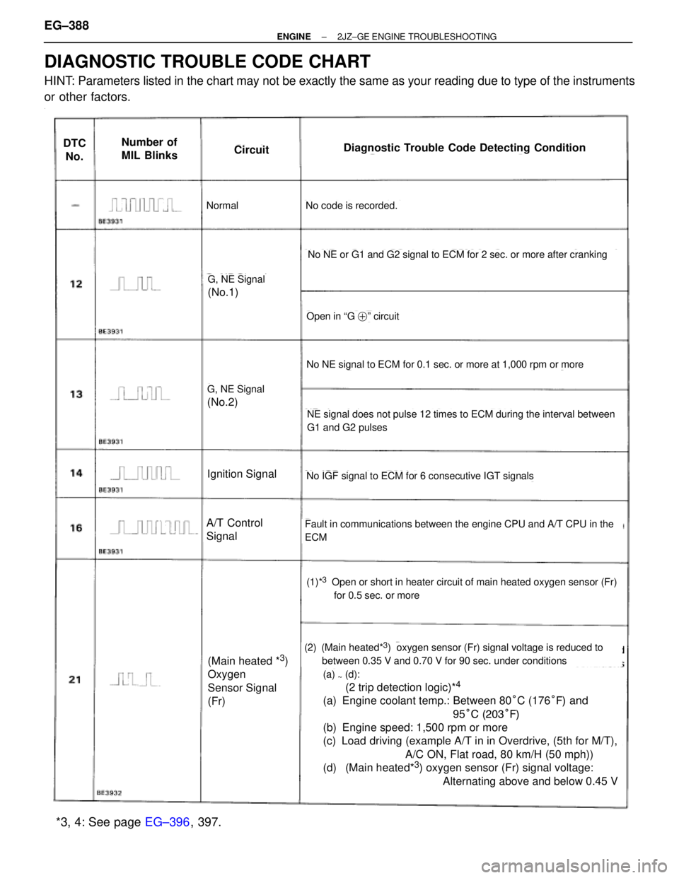
DIAGNOSTIC TROUBLE CODE CHART
HINT: Parameters listed in the chart may not be exactly the same as your reading due to type of the instruments
or other factors.
~
DTC
No.Number of
MIL BlinksCircuitDiagnostic Trouble Code Detecting Condition
NormalNo code is recorded.
G, NE Signal
(No.1)
G, NE Signal
(No.2)
Ignition Signal
A/T Control
Signal
(Main heated *3)
Oxygen
Sensor Signal
(Fr)
No NE or G1 and G2 signal to ECM for 2 sec. or more after cranking
Open in ªG �º circuit
No NE signal to ECM for 0.1 sec. or more at 1,000 rpm or more
NE signal does not pulse 12 times to ECM during the interval between
G1 and G2 pulses
No IGF signal to ECM for 6 consecutive IGT signals
Fault in communications between the engine CPU and A/T CPU in the
ECM
(1)*3Open or short in heater circuit of main heated oxygen sensor (Fr)
for 0.5 sec. or more
(2) (Main heated*3) oxygen sensor (Fr) signal voltage is reduced to
between 0.35 V and 0.70 V for 90 sec. under conditions
(a) ~ (d):
(2 trip detection logic)*4
(a) Engine coolant temp.: Between 80°C (176°F) and
95°C (203°F)
(b) Engine speed: 1,500 rpm or more
(c) Load driving (example A/T in in Overdrive, (5th for M/T),
A/C ON, Flat road, 80 km/H (50 mph))
(d) (Main heated*
3) oxygen sensor (Fr) signal voltage:
Alternating above and below 0.45 V
*3, 4: See page EG±396, 397. EG±388
± ENGINE2JZ±GE ENGINE TROUBLESHOOTING
Page 1898 of 2543
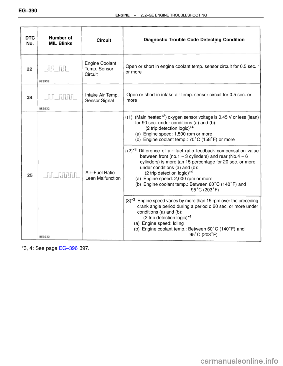
DTC
No.Number of
MIL BlinksCircuitDiagnostic Trouble Code Detecting Condition
Engine Coolant
Temp. Sensor
Circuit
Intake Air Temp.
Sensor Signal
Air±Fuel Ratio
Lean Malfunction
Open or short in engine coolant temp. sensor circuit for 0.5 sec.
or more
Open or short in intake air temp. sensor circuit for 0.5 sec. or
more
(1) (Main heated*3) oxygen sensor voltage is 0.45 V or less (lean)
for 90 sec. under conditions (a) and (b):
(2 trip detection logic)*
4
(a) Engine speed: 1,500 rpm or more
(b) Engine coolant temp.: 70°C (158°F) or more
(2)*3Difference of air±fuel ratio feedback compensation value
between front (no.1 ~ 3 cylinders) and rear (No.4 ~ 6
cylinders) is more tan 15 percentage for 20 sec. or more
under conditions (a) and (b):
(2 trip detection logic)*
4
(a) Engine speed: 2,000 rpm or more
(b) Engine coolant temp.: Between 60°C (140°F) and
95°C (203°F)
(3)*3Engine speed varies by more than 15 rpm over the preceding
crank angle period during a period o 20 sec. or more under
conditions (a) and (b):
(2 trip detection logic)*
4
(a) Engine speed: Idling
(b) Engine coolant temp.: Between 60°C (140°F) and
95°C (203°F)
*3, 4: See page EG±396 397. EG±390
± ENGINE2JZ±GE ENGINE TROUBLESHOOTING