Page 1429 of 2543
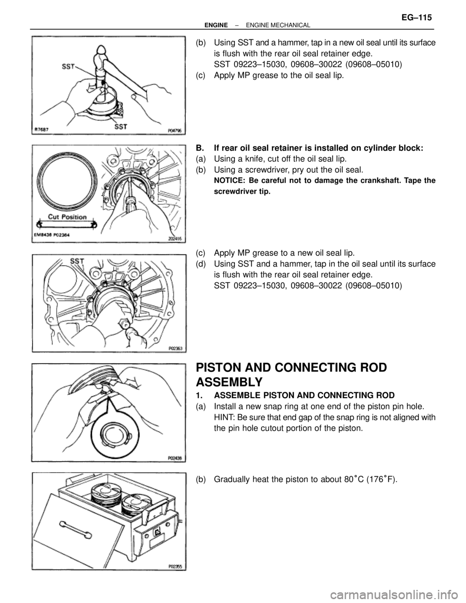
(b) Using SST and a hammer, tap in a new oil seal until its surface
is flush with the rear oil seal retainer edge.
SST 09223±15030, 09608±30022 (09608±05010)
(c) Apply MP grease to the oil seal lip.
B. If rear oil seal retainer is installed on cylinder block:
(a) Using a knife, cut off the oil seal lip.
(b) Using a screwdriver, pry out the oil seal.
NOTICE: Be careful not to damage the crankshaft. Tape the
screwdriver tip.
(c) Apply MP grease to a new oil seal lip.
(d) Using SST and a hammer, tap in the oil seal until its surface
is flush with the rear oil seal retainer edge.
SST 09223±15030, 09608±30022 (09608±05010)
PISTON AND CONNECTING ROD
ASSEMBLY
1. ASSEMBLE PISTON AND CONNECTING ROD
(a) Install a new snap ring at one end of the piston pin hole.
HINT: Be sure that end gap of the snap ring is not aligned with
the pin hole cutout portion of the piston.
(b) Gradually heat the piston to about 80°C (176°F).
± ENGINEENGINE MECHANICALEG±115
Page 1432 of 2543
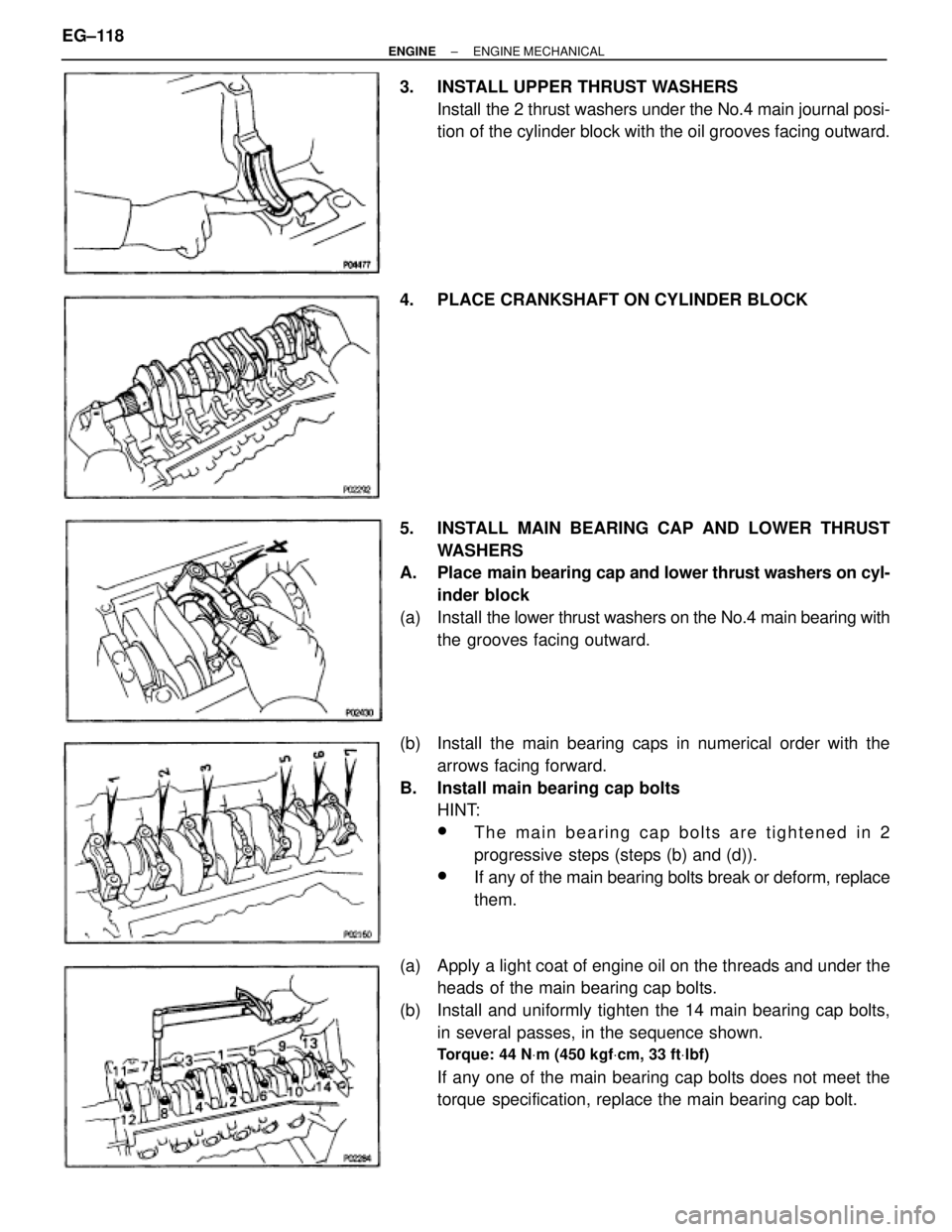
3. INSTALL UPPER THRUST WASHERS
Install the 2 thrust washers under the No.4 main journal posi-
tion of the cylinder block with the oil grooves facing outward.
4. PLACE CRANKSHAFT ON CYLINDER BLOCK
5. INSTALL MAIN BEARING CAP AND LOWER THRUST
WASHERS
A. Place main bearing cap and lower thrust washers on cyl-
inder block
(a) Install the lower thrust washers on the No.4 main bearing with
the grooves facing outward.
(b) Install the main bearing caps in numerical order with the
arrows facing forward.
B. Install main bearing cap bolts
HINT:
wThe main bearing cap bolts are tightened in 2
progressive steps (steps (b) and (d)).
wIf any of the main bearing bolts break or deform, replace
them.
(a) Apply a light coat of engine oil on the threads and under the
heads of the main bearing cap bolts.
(b) Install and uniformly tighten the 14 main bearing cap bolts,
in several passes, in the sequence shown.
Torque: 44 NVm (450 kgfVcm, 33 ftVlbf)
If any one of the main bearing cap bolts does not meet the
torque specification, replace the main bearing cap bolt. EG±118
± ENGINEENGINE MECHANICAL
Page 1433 of 2543
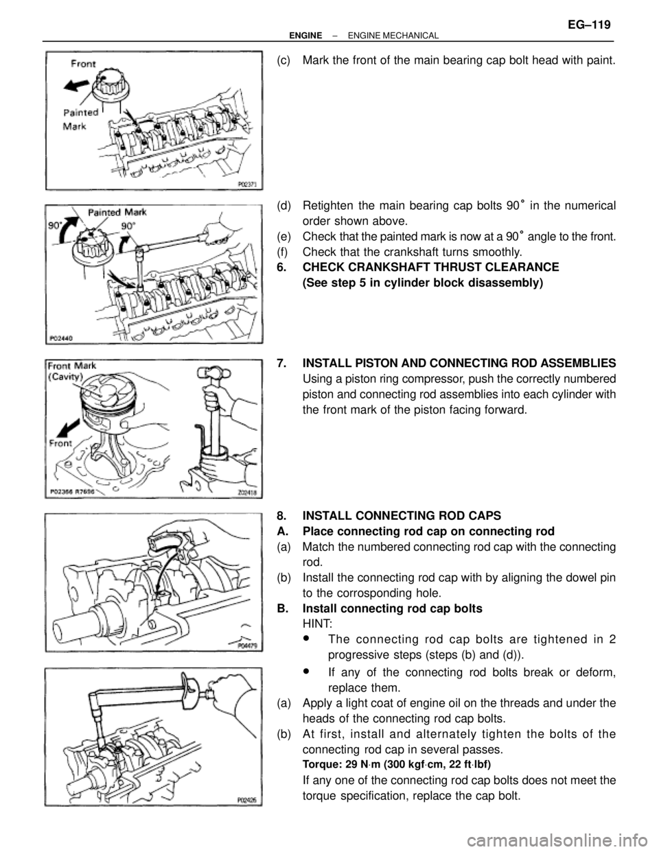
(c) Mark the front of the main bearing cap bolt head with paint.
(d) Retighten the main bearing cap bolts 90° in the numerical
order shown above.
(e) Check that the painted mark is now at a 90° angle to the front.
(f) Check that the crankshaft turns smoothly.
6. CHECK CRANKSHAFT THRUST CLEARANCE
(See step 5 in cylinder block disassembly)
7. INSTALL PISTON AND CONNECTING ROD ASSEMBLIES
Using a piston ring compressor, push the correctly numbered
piston and connecting rod assemblies into each cylinder with
the front mark of the piston facing forward.
8. INSTALL CONNECTING ROD CAPS
A. Place connecting rod cap on connecting rod
(a) Match the numbered connecting rod cap with the connecting
rod.
(b) Install the connecting rod cap with by aligning the dowel pin
to the corrosponding hole.
B. Install connecting rod cap bolts
HINT:
wThe connecting rod cap bolts are tightened in 2
progressive steps (steps (b) and (d)).
wIf any of the connecting rod bolts break or deform,
replace them.
(a) Apply a light coat of engine oil on the threads and under the
heads of the connecting rod cap bolts.
(b) A t first, in sta ll an d alte rn a te ly tig h te n th e bo lts of th e
connecting rod cap in several passes.
Torque: 29 NVm (300 kgfVcm, 22 ftVlbf)
If any one of the connecting rod cap bolts does not meet the
torque specification, replace the cap bolt.
± ENGINEENGINE MECHANICALEG±119
Page 1434 of 2543
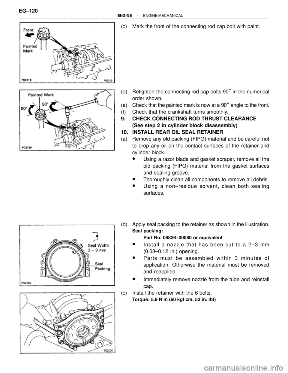
(c) Mark the front of the connecting rod cap bolt with paint.
(d) Retighten the connecting rod cap bolts 90° in the numerical
order shown.
(e) Check that the painted mark is now at a 90° angle to the front.
(f) Check that the crankshaft turns smoothly.
9. CHECK CONNECTING ROD THRUST CLEARANCE
(See step 2 in cylinder block disassembly)
10. INSTALL REAR OIL SEAL RETAINER
(a) Remove any old packing (FIPG) material and be careful not
to drop any oil on the contact surfaces of the retainer and
cylinder block.
wUsing a razor blade and gasket scraper, remove all the
old packing (FIPG) material from the gasket surfaces
and sealing groove.
wThoroughly clean all components to remove all debris.
wUsing a non±residue solvent, clean both sealing
surfaces.
(b) Apply seal packing to the retainer as shown in the illustration.
Seal packing:
Part No. 08826±00080 or equivalent
wInstall a nozzle that has been cut to a 2±3 mm
(0.08±0.12 in.) opening.
wParts must be assembled within 3 minutes of
application. Otherwise the material must be removed
and reapplied.
wImmediately remove nozzle from the tube and reinstall
cap.
(c) Install the retainer with the 6 bolts.
Torque: 5.9 NVm (60 kgfVcm, 52 in.Vlbf)
EG±120± ENGINEENGINE MECHANICAL
Page 1435 of 2543
AFTER ASSEMBLY
1. INSTALL OIL PUMP
(See oil pump installation in Lubrication System)
2. INSTALL WATER PUMP
(See water pump installation in Cooling System)
3. 2JZ±GTE:
INSTALL CRANKSHAFT POSITION SENSOR
Torque: 8.8 NVm (90 kgfVcm, 78 in.Vlbf)
4. INSTALL RH ENGINE MOUNTING BRACKET AND
INSULATOR ASSEMBLY
HINT: The RH mounting bracket is marked ºA u EXº.
Torque: 58 NVm (590 kgfVcm, 43 ftVlbf)
5. INSTALL ENGINE COOLANT DRAIN PLUG
Torque: 29 NVm (300 kgfVcm, 22 ftVlbf)
6. 2JZ±GTE:
INSTALL UNION FOR OIL COOLER HOSE
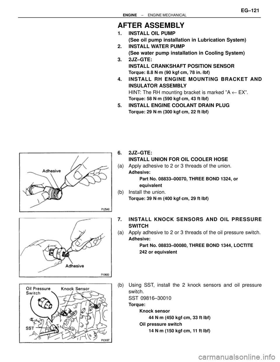
(a) Apply adhesive to 2 or 3 threads of the union.
Adhesive:
Part No. 08833±00070, THREE BOND 1324, or
equivalent
(b) Install the union.
Torque: 39 NVm (400 kgfVcm, 29 ftVlbf)
7. INSTALL KNOCK SENSORS AND OIL PRESSURE
SWITCH
(a) Apply adhesive to 2 or 3 threads of the oil pressure switch.
Adhesive:
Part No. 08833±00080, THREE BOND 1344, LOCTITE
242 or equivalent
(b) Using SST, install the 2 knock sensors and oil pressure
switch.
SST 09816±30010
Torque:
Knock sensor
44 NVm (450 kgfVcm, 33 ftVlbf)
Oil pressure switch
14 NVm (150 kgfVcm, 11 ftVlbf)
± ENGINEENGINE MECHANICALEG±121
Page 1436 of 2543
8. INSTALL FUEL PIPE SUPPORT
Torque: 14 NVm (145 kgfVcm, 10 ftVlbf)
9. INSTALL LH ENGINE MOUNTING BRACKET AND
INSULATOR ASSEMBLY
HINT: LH mounting bracket is marked ºA u INº.
Torque: 58 NVm (590 kgfVcm, 43 ftVlbf)
10. INSTALL OIL FILTER BRACKET
(a) Check and clean the oil filter bracket installation.
(b) Place a new O±ring in position on the oil filter bracket.
(c) Apply clean engine oil to the O±ring.
(d) Install a new gasket to the union bolt.
(e) Install the oil filter braket with the union bolt.
Torque: 88 NVm (900 kgfVcm, 65 ftVlbf)
11. INSTALL NO.2 WATER BYPASS PIPE
(a) Install a new gasket to the water pump.
(b) 2JZ±GE:
Install the water bypass pipe with the bolt and 2 nuts.
Torque: 21 NVm (210 kgfVcm, 15 ftVlbf)
(c) 2JZ±GTE:
Install the water bypass pipe with the 2 bolts and 2 nuts.
Torque: 21 NVm (210 kgfVcm, 15 ftVlbf)
12. 2JZ±GTE:
INSTALL OIL COOLER
(See oil cooler installation in Lubrication System)
13. INSTALL OIL FILTER
(See oil and filter replacement in Lubrication System)
14. INSTALL CYLINDER HEAD
(See cylinder head installation)
15. INSTALL TIMING PULLEYS AND BELT
(See timing belt installation)
16. INSTALL GENERATOR
(See generator installation in Charging System)
17. REMOVE ENGINE STAND FROM ENGINE
18. M/T:
INSTALL FLYWHEEL
HINT: The flywheel bolts are tightened in 2 progressive step,
(b) and (d).
(a) Install the flywheel on the crankshaft.
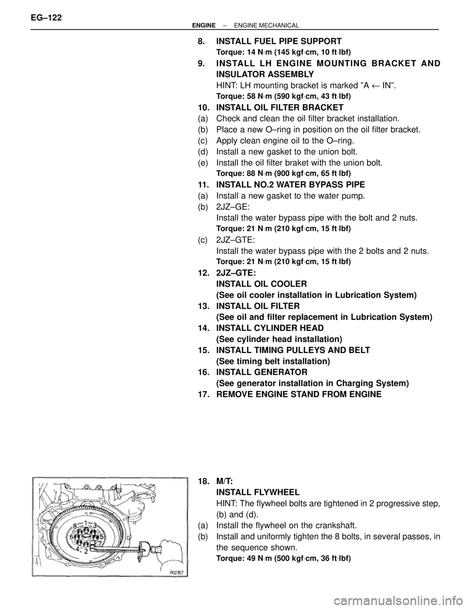
(b) Install and uniformly tighten the 8 bolts, in several passes, in
the sequence shown.
Torque: 49 NVm (500 kgfVcm, 36 ftVlbf)
EG±122± ENGINEENGINE MECHANICAL
Page 1437 of 2543
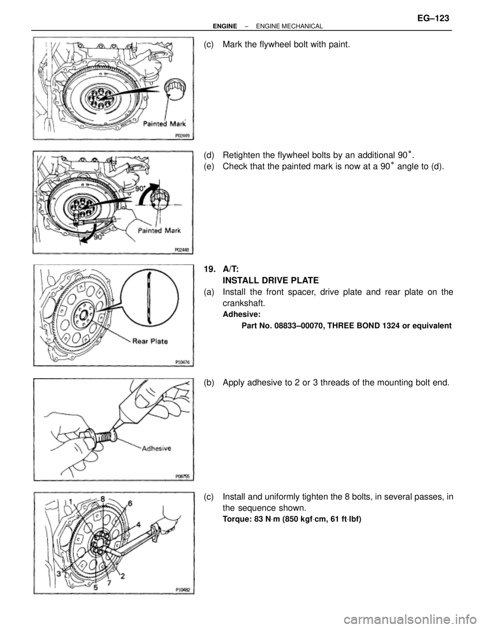
(c) Mark the flywheel bolt with paint.
(d) Retighten the flywheel bolts by an additional 90°.
(e) Check that the painted mark is now at a 90° angle to (d).
19. A/T:
INSTALL DRIVE PLATE
(a) Install the front spacer, drive plate and rear plate on the
crankshaft.
Adhesive:
Part No. 08833±00070, THREE BOND 1324 or equivalent
(b) Apply adhesive to 2 or 3 threads of the mounting bolt end.
(c) Install and uniformly tighten the 8 bolts, in several passes, in
the sequence shown.
Torque: 83 NVm (850 kgfVcm, 61 ftVlbf)
± ENGINEENGINE MECHANICALEG±123
Page 1439 of 2543
4. 2JZ±GTE M/T:
INSTALL CLUTCH COVER SET BOLTS
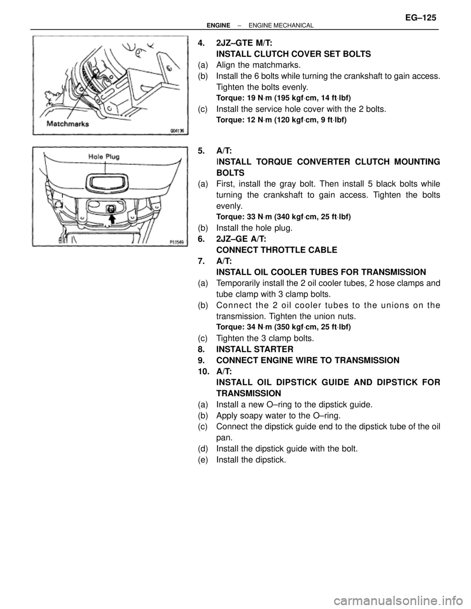
(a) Align the matchmarks.
(b) Install the 6 bolts while turning the crankshaft to gain access.
Tighten the bolts evenly.
Torque: 19 NVm (195 kgfVcm, 14 ftVlbf)
(c) Install the service hole cover with the 2 bolts.
Torque: 12 NVm (120 kgfVcm, 9 ftVlbf)
5. A/T:
INSTALL TORQUE CONVERTER CLUTCH MOUNTING
BOLTS
(a) First, install the gray bolt. Then install 5 black bolts while
turning the crankshaft to gain access. Tighten the bolts
evenly.
Torque: 33 NVm (340 kgfVcm, 25 ftVlbf)
(b) Install the hole plug.
6. 2JZ±GE A/T:
CONNECT THROTTLE CABLE
7. A/T:
INSTALL OIL COOLER TUBES FOR TRANSMISSION
(a) Temporarily install the 2 oil cooler tubes, 2 hose clamps and
tube clamp with 3 clamp bolts.
(b) Connect the 2 oil cooler tubes to the unions on the
transmission. Tighten the union nuts.
Torque: 34 NVm (350 kgfVcm, 25 ftVlbf)
(c) Tighten the 3 clamp bolts.
8. INSTALL STARTER
9. CONNECT ENGINE WIRE TO TRANSMISSION
10. A/T:
INSTALL OIL DIPSTICK GUIDE AND DIPSTICK FOR
TRANSMISSION
(a) Install a new O±ring to the dipstick guide.
(b) Apply soapy water to the O±ring.
(c) Connect the dipstick guide end to the dipstick tube of the oil
pan.
(d) Install the dipstick guide with the bolt.
(e) Install the dipstick.
± ENGINEENGINE MECHANICALEG±125