Page 1232 of 2543

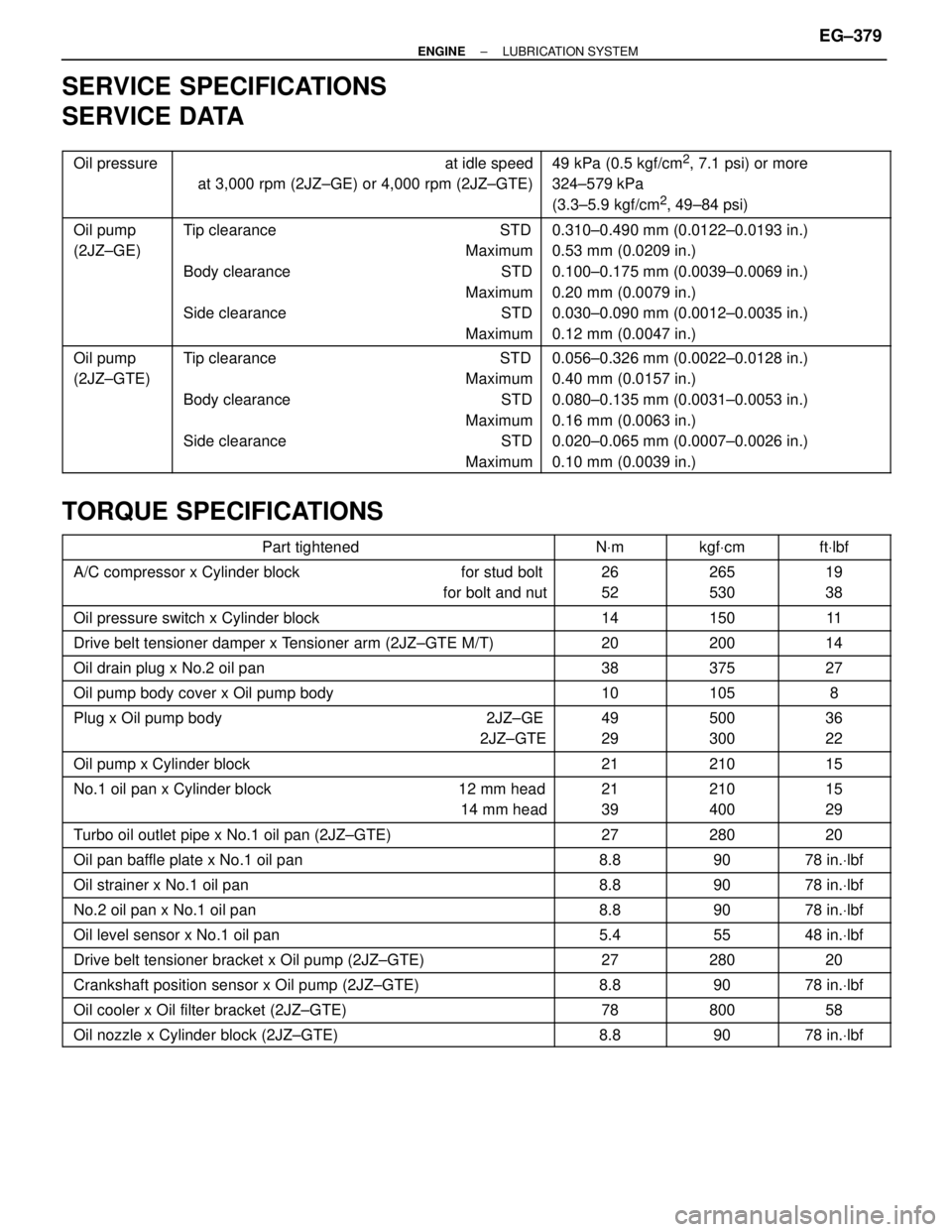
SERVICE SPECIFICATIONS
SERVICE DATA
������ �
����� �
����� ������
Oil pressure���������������� �
��������������� �
��������������� ����������������
at idle speed
at 3,000 rpm (2JZ±GE) or 4,000 rpm (2JZ±GTE)���������������� �
��������������� �
��������������� ����������������
49 kPa (0.5 kgf/cm2, 7.1 psi) or more
324±579 kPa
(3.3±5.9 kgf/cm
2, 49±84 psi)
������ �
����� �
����� �
����� �
����� ������
Oil pump
(2JZ±GE)���������������� �
��������������� �
��������������� �
��������������� �
��������������� ����������������
Tip clearance STD
Maximum
Body clearance STD
Maximum
Side clearance STD
Maximum���������������� �
��������������� �
��������������� �
��������������� �
��������������� ����������������
0.310±0.490 mm (0.0122±0.0193 in.)
0.53 mm (0.0209 in.)
0.100±0.175 mm (0.0039±0.0069 in.)
0.20 mm (0.0079 in.)
0.030±0.090 mm (0.0012±0.0035 in.)
0.12 mm (0.0047 in.)
������ �
����� �
����� �
����� �
����� ������
Oil pump
(2JZ±GTE)���������������� �
��������������� �
��������������� �
��������������� �
��������������� ����������������
Tip clearance STD
Maximum
Body clearance STD
Maximum
Side clearance STD
Maximum���������������� �
��������������� �
��������������� �
��������������� �
��������������� ����������������
0.056±0.326 mm (0.0022±0.0128 in.)
0.40 mm (0.0157 in.)
0.080±0.135 mm (0.0031±0.0053 in.)
0.16 mm (0.0063 in.)
0.020±0.065 mm (0.0007±0.0026 in.)
0.10 mm (0.0039 in.)
TORQUE SPECIFICATIONS
���������������������� ����������������������Part tightened����� �����NVm������ ������kgfVcm������ ������ftVlbf
���������������������� �
��������������������� ����������������������
A/C compressor x Cylinder block for stud bolt
for bolt and nut����� �
���� �����
26
52������ �
����� ������
265
530������ �
����� ������
19
38
���������������������� ����������������������Oil pressure switch x Cylinder block����� �����14������ ������150������ ������11
���������������������� ����������������������Drive belt tensioner damper x Tensioner arm (2JZ±GTE M/T)����� �����20������ ������200������ ������14
���������������������� ����������������������Oil drain plug x No.2 oil pan����� �����38������ ������375������ ������27
���������������������� ����������������������Oil pump body cover x Oil pump body����� �����10������ ������105������ ������8
���������������������� �
��������������������� ����������������������
Plug x Oil pump body 2JZ±GE
2JZ±GTE����� �
���� �����
49
29������ �
����� ������
500
300������ �
����� ������
36
22
���������������������� ����������������������Oil pump x Cylinder block����� �����21������ ������210������ ������15
���������������������� �
��������������������� ����������������������
No.1 oil pan x Cylinder block 12 mm head
14 mm head����� �
���� �����
21
39������ �
����� ������
210
400������ �
����� ������
15
29
���������������������� ����������������������Turbo oil outlet pipe x No.1 oil pan (2JZ±GTE)����� �����27������ ������280������ ������20
���������������������� ����������������������Oil pan baffle plate x No.1 oil pan����� �����8.8������ ������90������ ������78 in.Vlbf
���������������������� ����������������������Oil strainer x No.1 oil pan����� �����8.8������ ������90������ ������78 in.Vlbf
���������������������� ����������������������No.2 oil pan x No.1 oil pan����� �����8.8������ ������90������ ������78 in.Vlbf
���������������������� ����������������������Oil level sensor x No.1 oil pan����� �����5.4������ ������55������ ������48 in.Vlbf
���������������������� ����������������������Drive belt tensioner bracket x Oil pump (2JZ±GTE)����� �����27������ ������280������ ������20���������������������� ����������������������Crankshaft position sensor x Oil pump (2JZ±GTE)����� �����8.8������ ������90������ ������78 in.Vlbf���������������������� ����������������������Oil cooler x Oil filter bracket (2JZ±GTE)����� �����78������ ������800������ ������58���������������������� ����������������������Oil nozzle x Cylinder block (2JZ±GTE)����� �����8.8������ ������90������ ������78 in.Vlbf
± ENGINELUBRICATION SYSTEMEG±379
Page 1317 of 2543
ENGINE MECHANICAL
PREPARATION
SST (SPECIAL SERVICE TOOLS)
09201±10000 Valve Guide Bushing Remover &
Replacer Set
(09201±01060) Valve Guide Bushing Remover &
Replacer 6
09202±70010 Valve Spring Compressor
09213±70010 Crankshaft Pulley Holding Tool
09222±30010Connecting Rod Bushing Remover
& Replacer
09223±15030 Oil Seal & Bearing ReplacerCrankshaft rear oil seal
09248±55040 Valve Clearance Adjust Tool Set
(09248±05410) Valve Lifter Press
(09248±05420) Valve Lifter Stopper
09301±00110 Clutch Guide Tool2JZ±GE M/T
09316±60010 Transmission & Transfer Bearing
Replacer
(09316±00010) Replacer PipeCrankshaft front oil seal
Camshaft oil seal
± ENGINEENGINE MECHANICALEG±3
Page 1318 of 2543
(09316±00050) Replacer ªDº
09330±00021Companion Flange Holding Tool
09608±30022 Front Hub Bearing Replacer Set
(09608±05010) Handle
09816±30010 Oil Pressure Switch Socket
09843±18020 Diagnosis Check Wire
09950±50010 Puller C Set
(09951±05010)Hanger 150
(09952±05010) Slide Arm
(09953±05020) Center Bolt 150
(09954±05010)Claw No.1
(09954±05030)Claw No.3
09960±10010 Variable Pin Wrench Set
(09962±01000) Variable Pin Wrench Arm AssyCamshaft timing pulley
Camshaft pulley
Crankshaft timing pulley
Crankshaft pulley
Crankshaft timing pulley
Crankshaft pulley
Crankshaft timing pulley
Crankshaft pulley
Crankshaft timing pulley
Knock sensor
Oil pressure switch
Crankshaft rear oil seal
Valve guide bushing
Crankshaft pulley
Camshaft oil seal
EG±4± ENGINEENGINE MECHANICAL
Page 1325 of 2543

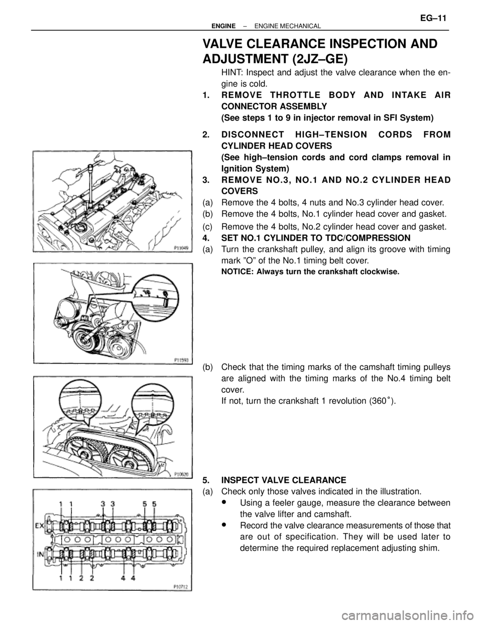
VALVE CLEARANCE INSPECTION AND
ADJUSTMENT (2JZ±GE)
HINT: Inspect and adjust the valve clearance when the en-
gine is cold.
1. REMOVE THROTTLE BODY AND INTAKE AIR
CONNECTOR ASSEMBLY
(See steps 1 to 9 in injector removal in SFI System)
2. DISCONNECT HIGH±TENSION CORDS FROM
CYLINDER HEAD COVERS
(See high±tension cords and cord clamps removal in
Ignition System)
3. REMOVE NO.3, NO.1 AND NO.2 CYLINDER HEAD
COVERS
(a) Remove the 4 bolts, 4 nuts and No.3 cylinder head cover.
(b) Remove the 4 bolts, No.1 cylinder head cover and gasket.
(c) Remove the 4 bolts, No.2 cylinder head cover and gasket.
4. SET NO.1 CYLINDER TO TDC/COMPRESSION
(a) Turn the crankshaft pulley, and align its groove with timing
mark ºOº of the No.1 timing belt cover.
NOTICE: Always turn the crankshaft clockwise.
(b) Check that the timing marks of the camshaft timing pulleys
are aligned with the timing marks of the No.4 timing belt
cover.
If not, turn the crankshaft 1 revolution (360°).
5. INSPECT VALVE CLEARANCE
(a) Check only those valves indicated in the illustration.
wUsing a feeler gauge, measure the clearance between
the valve lifter and camshaft.
wRecord the valve clearance measurements of those that
are out of specification. They will be used later to
determine the required replacement adjusting shim.
± ENGINEENGINE MECHANICALEG±11
Page 1326 of 2543
Valve clearance (Cold):
Intake
.15±0.25 mm (0.006±0.010 in.)
Exhaust
.25±0.35 mm (0.010±0.014 in.)
(b) Turn the crankshaft pulley 1 revolution (360°), and align the
groove with timing mark ºOº of the No.1 timing belt cover.
(c) Check only the valves indicated as shown. Measure the valve
clearance. (See procedure in step (a))
6. ADJUST VALVE CLEARANCE
(a) Remove the adjusting shim.
wTurn the camshaft so that the cam lobe for the valve to
be adjusted faces up.
wTurn the valve lifter with a screwdriver so that the
notches are perpendicular to the camshaft.
wUsing SST (A), hold the camshaft as shown in the
illustration.
SST 09248±55040 (09248±05410)
wUsing SST (A), press down the valve lifter and place
SST (B) between the camshaft and valve lifter. Remove
SST (A).
SST 09248±55040 (09248±05410, 09248±05420)
HINT:
wApply SST (B) at slight angle on the side marked with
º7º, at the position shown in the illustration. EG±12
± ENGINEENGINE MECHANICAL
Page 1339 of 2543
7. SET NO.1 CYLINDER TO TDC/COMPRESSION
(a) Turn the crankshaft pulley, and align its groove with timing
mark ºOº of the No.1 timing belt cover.
NOTICE: Always turn the crankshaft clockwise.
(b) Check that the timing marks of the camshaft timing pulleys
are aligned with the timing marks of the No.4 timing belt
cover.
If not, turn the crankshaft 1 revolution (360°).
8. REMOVE TIMING BELT FROM CAMSHAFT TIMING
PULLEYS
HINT (Re±using timing belt): Place matchmarks on the timing
belt and camshaft timing pulleys as shown in the illustration.
(a) Alternately loosen the 2 bolts, and remove them, the
tensioner and dust boot.
(b) Disconnect the timing belt from the camshaft timing pulleys.
± ENGINEENGINE MECHANICALEG±25
Page 1340 of 2543
9. REMOVE CAMSHAFT TIMING PULLEYS
Using SST, remove the pulley bolt. Remove the 2 timing pul-
leys.
SST 09960±10010 (09962±01000, 09963±01000)
10. A/T:
DISCONNECT OIL COOLER TUBES
Remove the 2 bolts and hose clamps, and disconnect oil
cooler tubes.
11. REMOVE CRANKSHAFT PULLEY
(a) Using SST, loosen the pulley bolt.
SST 09213±70010, 09330±00021
(b) Remove the pulley bolt.
(c) Using SST, remove the pulley.
SST 09950±50010 (09954±05030, 09551±05010,
09552±05010, 09553±05020)
12. 2JZ±GE:
REMOVE PS PUMP FRONT BRACKET
Remove the 3 bolts, plate washer and pump front bracket. EG±26
± ENGINEENGINE MECHANICAL
Page 1341 of 2543
13. REMOVE NO.1 TIMING BELT COVER
Remove the 5 bolts, timing belt cover and gasket.
14. REMOVE TIMING BELT GUIDE
15. REMOVE TIMING BELT
HINT (When re±using timing belt): Draw an arrow on the tim-
ing belt in the direction of engine revolution, and place match-
marks on the timing belt and crankshaft timing pulley.
16. REMOVE IDLER PULLEY
Using a 10 mm hexagon wrench, remove the pivot bolt, plate
washer and idler pulley.
17. REMOVE CRANKSHAFT TIMING PULLEY
(a) 2JZ±GTE:
Remove the bolt and timing belt plate.
(b) Remove the crankshaft timing pulley.
If the pulley cannot be removed by hand, use SST to remove
the crankshaft timing pulley.
SST 09950±50010 (09951±05010, 09952±05010,
09953±05020, 09954±00010)
± ENGINEENGINE MECHANICALEG±27