Page 984 of 2543
Check for Fluid Leakage
± BRAKE SYSTEMANTI±LOCK BRAKE SYSTEM (ABS)BR±115
Page 993 of 2543
P. BR±125
P. BR±126 ~ BR±128
P. BR±24
P. BR±126
P. BR±128P. BR±133
P. BR±165P. BR±134 ~ P. BR±163
Vehicle brought to workshop
Customer Problem Analysis
Check and Clear Diagnostic Trouble Codes (Precheck)
Problem Symptom ConfirmationSymptom Simulation
Diagnostic Trouble Code Check
Diagnostic Trouble Code ChartProblem Symptoms Chart
Check for Fluid LeakageCircuit InspectionSensor Check
Identification of Problem
Repair
Confirmation Test
Items insideare titles of pages in this manual,
with the page number in the bottom portion. See the
pages for detailed explanation.
Perform troubleshooting in accordance with the procedure on the following pages.
EndStep [2] , [5] , [9] , [11] : Diagnostic steps permitting the use
of the TOYOTA hand±held tester.
Symptom
does not occur
Symptom
occurs
Normal code
HOW TO PROCEED WITH TROUBLESHOOTING
BR±124± BRAKE SYSTEMTRACTION CONTROL SYSTEM (TRAC)
Page 999 of 2543
ECU TERMINALS STANDARD VALUE
ABS & TRAC ECU:
ConditionSTD Voltage (V)Symbols
(Terminals No.)
Always
IG switch ON
IG switch ON, ABS warning light OFF
IG switch ON
IG switch ON, TRAC and TRAC OFF indicator light OFF
IG switch ON
IG switch ON, ABS warning light OFF
IG switch ON, ABS warning light OFF
IG switch ON, ABS warning light OFF
IG switch ON, ABS warning light OFF
IG switch ON, ABS warning light OFF
IG switch ON, TRAC and TRAC OFF indicator light OFF
IG switch ON, TRAC and TRAC OFF indicator light OFF
IG switch ON, ABS warning light ON
IG switch ON, ABS warning light OFF
IG switch ON, PKB switch ON
Fluid in M/C reservoir above MIN level.
IG switch ON, PKB switch OFF
Fluid in M/C reservoir above MIN level.
IG switch ON
Fluid in M/C reservoir above MIN level.
Stop light switch OFF
Stop light switch ON
IG switch ON, ABS warning light OFF
BR±130± BRAKE SYSTEMTRACTION CONTROL SYSTEM (TRAC)
Page 1001 of 2543

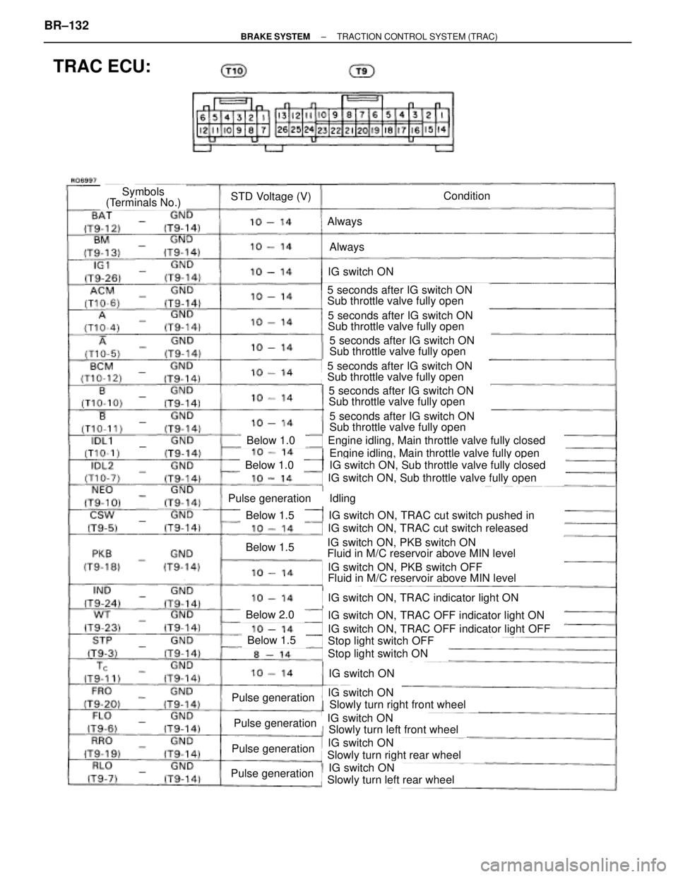
TRAC ECU:
ConditionSTD Voltage (V)Symbols
(Terminals No.)
Always
Always
IG switch ON
5 seconds after IG switch ON
Sub throttle valve fully open
5 seconds after IG switch ON
Sub throttle valve fully open
5 seconds after IG switch ON
Sub throttle valve fully open
5 seconds after IG switch ON
Sub throttle valve fully open
5 seconds after IG switch ON
Sub throttle valve fully open
5 seconds after IG switch ON
Sub throttle valve fully open
Engine idling, Main throttle valve fully closed
Engine idling, Main throttle valve fully open
IG switch ON, Sub throttle valve fully closed
IG switch ON, Sub throttle valve fully open
Idling
IG switch ON, TRAC cut switch pushed in
IG switch ON, TRAC cut switch released
IG switch ON, PKB switch ON
Fluid in M/C reservoir above MIN level
IG switch ON, PKB switch OFF
Fluid in M/C reservoir above MIN level
IG switch ON, TRAC indicator light ON
IG switch ON, TRAC OFF indicator light ON
IG switch ON, TRAC OFF indicator light OFF
Stop light switch OFF
Stop light switch ON
IG switch ON
IG switch ON
Slowly turn right front wheel
IG switch ON
Slowly turn left front wheel
IG switch ON
Slowly turn right rear wheel
IG switch ON
Slowly turn left rear wheel
Below 1.0
Below 1.0
Pulse generation
Below 1.5
Below 1.5
Below 2.0
Below 1.5
Pulse generation
Pulse generation
Pulse generation
Pulse generation
BR±132± BRAKE SYSTEMTRACTION CONTROL SYSTEM (TRAC)
Page 1034 of 2543
Check for Fluid Leakage
± BRAKE SYSTEMTRACTION CONTROL SYSTEM (TRAC)BR±165
Page 1204 of 2543

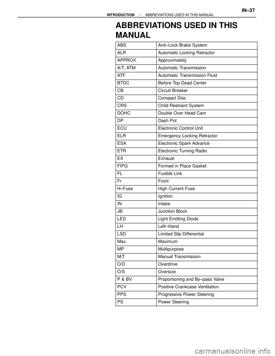
ABBREVIATIONS USED IN THIS
MANUAL
������� �������ABS���������������� ����������������Anti±Lock Brake System
������� �������ALR���������������� ����������������Automatic Locking Retractor
������� �������APPROX.���������������� ����������������Approximately
������� �������A/T, ATM���������������� ����������������Automatic Transmission
������� �������AT F���������������� ����������������Automatic Transmission Fluid
������� �������BTDC���������������� ����������������Before Top Dead Center
������� �������CB���������������� ����������������Circuit Breaker
������� �������CD���������������� ����������������Compact Disc������� �������CRS���������������� ����������������Child Restraint System������� �������DOHC���������������� ����������������Double Over Head Cam������� �
������ �������DP
���������������� �
��������������� ����������������Dash Pot
������� �������ECU���������������� ����������������Electronic Control Unit
������� �������ELR���������������� ����������������Emergency Locking Retractor
������� �������ESA���������������� ����������������Electronic Spark Advance
������� �������ETR���������������� ����������������Electronic Turning Radio
������� �������EX���������������� ����������������Exhaust
������� �������FIPG���������������� ����������������Formed in Place Gasket
������� �������FL���������������� ����������������Fusible Link
������� �������Fr���������������� ����������������Front������� �������H±Fuse���������������� ����������������High Current Fuse������� �
������ �������IG���������������� �
��������������� ����������������Ignition
������� �������IN���������������� ����������������Intake
������� �������JB���������������� ����������������Junction Block
������� �������LED���������������� ����������������Light Emitting Diode
������� �������LH���������������� ����������������Left±Hand
������� �������LSD���������������� ����������������Limited Slip Differential
������� �������Max.���������������� ����������������Maximum
������� �������MP���������������� ����������������Multipurpose
������� �������M/T���������������� ����������������Manual Transmission������� �������O/D���������������� ����������������Overdrive������� �������O/S���������������� ����������������Oversize������� �
������ �������P & BV
���������������� �
��������������� ����������������Proportioning and By±pass Valve
������� �������PCV���������������� ����������������Positive Crankcase Ventilation
������� �������PPS���������������� ����������������Progressive Power Steering
������� �������PS���������������� ����������������Power Steering
± INTRODUCTIONABBREVIATIONS USED IN THIS MANUALIN±37
Page 1238 of 2543

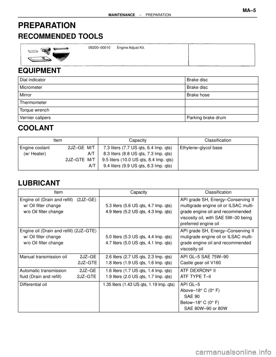
PREPARATION
RECOMMENDED TOOLS
09200±00010 Engine Adjust Kit.
EQUIPMENT
������������������������� �������������������������Dial indicator������������ ������������Brake disc
������������������������� �������������������������Micrometer������������ ������������Brake disc
������������������������� �������������������������Mirror������������ ������������Brake hose
������������������������� �������������������������Thermometer������������ ������������
������������������������� �������������������������Torque wrench������������ ������������
������������������������� �������������������������Vernier calipers������������ ������������Parking brake drum
COOLANT
������������� �������������Item������������ ������������Capacity������������� �������������Classification������������� �
������������ �������������Engine coolant 2JZ±GE M/T
(w/ Heater) A/T7.3 liters (7.7 US qts, 6.4 lmp. qts)
8.3 liters (8.8 US qts, 7.3 lmp. qts)Ethylene±glycol base
������������� �
������������ �������������
()
2JZ±GTE M/T
A/T
(q q)
9.5 liters (10.0 US qts, 8.4 lmp. qts)
9.4 liters (9.9 US qts, 8.3 lmp. qts)
LUBRICANT
������������� �������������Item������������ ������������Capacity������������� �������������Classification
������������� �
������������ �������������
Engine oil (Drain and refill) (2JZ±GE)
w/ Oil filter change
w/o Oil filter change
5.3 liters (5.6 US qts, 4.7 lmp. qts)
4 9 liters (5 2 US qts 4 3 lmpqts)
API grade SH, Energy±Conserving II
multigrade engine oil or ILSAC multi-
grade engine oil and recommended������������� �
������������ �������������
w/o Oil filter change4.9 liters (5.2 US qts, 4.3 lmp. qts)grade engine oil and recommended
viscosity oil, with SAE 5W±30 being
preferred engine oil
������������� �
������������ �������������Engine oil (Drain and refill) (2JZ±GTE)
w/ Oil filter change
5.0 liters (5.3 US qts, 4.4 lmp. qts)
API grade SH, Energy±Conserving II
mutigrade engine oil or ILSAC multi-
������������� �
������������ �������������
g
w/o Oil filter change
(q q)
4.7 liters (5.0 US qts, 4.1 lmp. qts)
gg
grade engine oil and recommended
viscosity oil
������������� �������������Manual transmission oil 2JZ±GE2.6 liters (2.7 US qts, 2.3 lmp. qts)API GL±5 SAE 75W±90
������������� ������������� 2JZ±GTE
(q, q)
1.8 liters (1.9 US qts, 1.6 lmp. qts)Castle gear oil V160
������������� �������������Automatic transmission 2JZ±GE1.6 liters (1.7 US qts, 1.4 lmp. qts)ATF DEXRON® II
������������� �������������fluid (Drain and refill) 2JZ±GTE
(q, q)
1.9 liters (2.0 US qts, 1.7 lmp. qts)ATF TYPE T±II
������������� �
������������ �������������
Differential oil1.35 liters (1.43 US qts, 1.19 lmp. qts)API GL±5
Above±185 C (05 F)
SAE 90������������� �
������������ �
������������ �������������
SAE 90
Below±185 C (05 F)
SAE 80W±90 or 80W
± MAINTENANCEPREPARATIONMA±5
Page 1246 of 2543

Front Passenger Airbag:
Visually inspect the front passenger airbag assembly (airbag
and inflater).
wUse the diagnosis check to check if there are
abnormalities.
wCheck that there are no cuts, cracks or noticeable color
changes in the front passenger airbag door.
wRemove the front passenger airbag assembly from the
vehicle and check the wiring and front passenger airbag
door for damage and corrosion due to rusting, etc.
If necessary, replace the front passenger airbag assembly.
CAUTION:
wFor removal and replacement of the steering wheel pad
or front passenger airbag assembly, see RS section and
be sure to perform the operation in the correct order.
wBefore disposing of the steering wheel pad or front pas-
senger airbag assembly must first be deployed by using
SST (See RS section).
18. INSPECT STEERING GEAR HOUSING OIL
Check the steering gear housing for oil leakage.
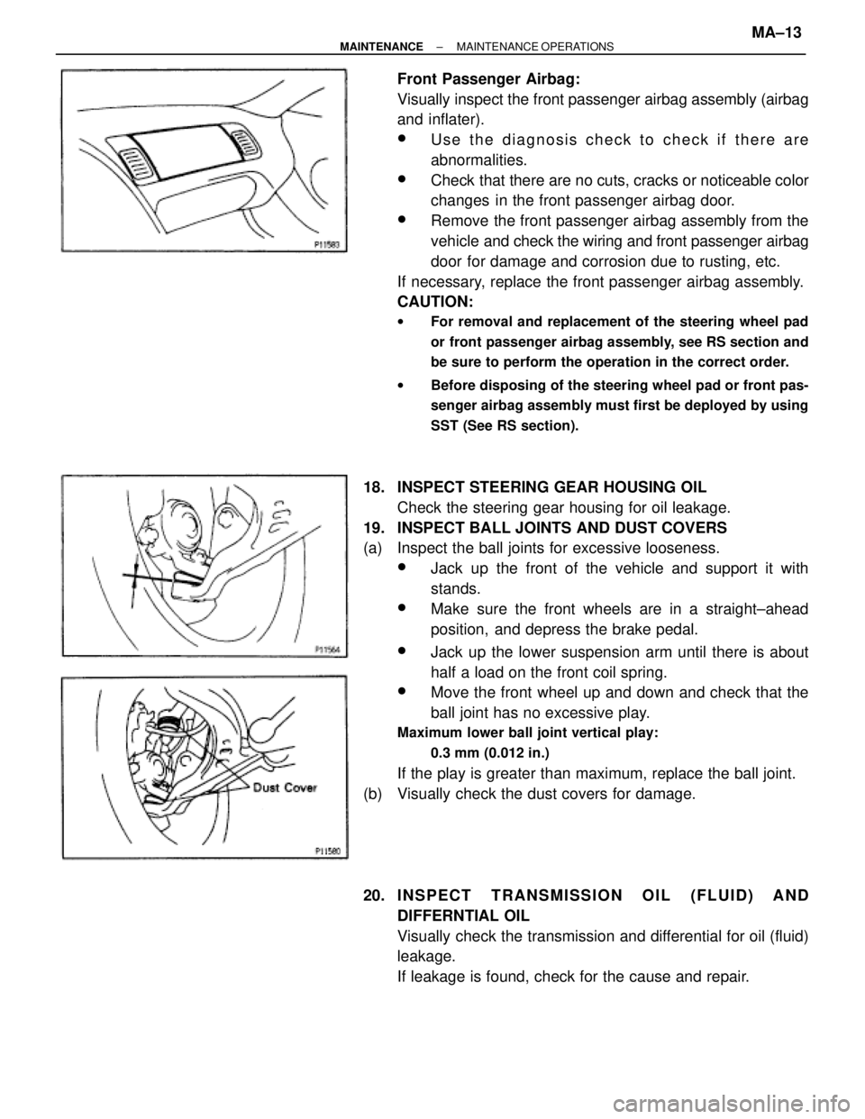
19. INSPECT BALL JOINTS AND DUST COVERS
(a) Inspect the ball joints for excessive looseness.
wJack up the front of the vehicle and support it with
stands.
wMake sure the front wheels are in a straight±ahead
position, and depress the brake pedal.
wJack up the lower suspension arm until there is about
half a load on the front coil spring.
wMove the front wheel up and down and check that the
ball joint has no excessive play.
Maximum lower ball joint vertical play:
0.3 mm (0.012 in.)
If the play is greater than maximum, replace the ball joint.
(b) Visually check the dust covers for damage.
20. I NSPECT TRANSMISSION OIL (FLUID) AND
DIFFERNTIAL OIL
Visually check the transmission and differential for oil (fluid)
leakage.
If leakage is found, check for the cause and repair.
± MAINTENANCEMAINTENANCE OPERATIONSMA±13