Page 910 of 2543
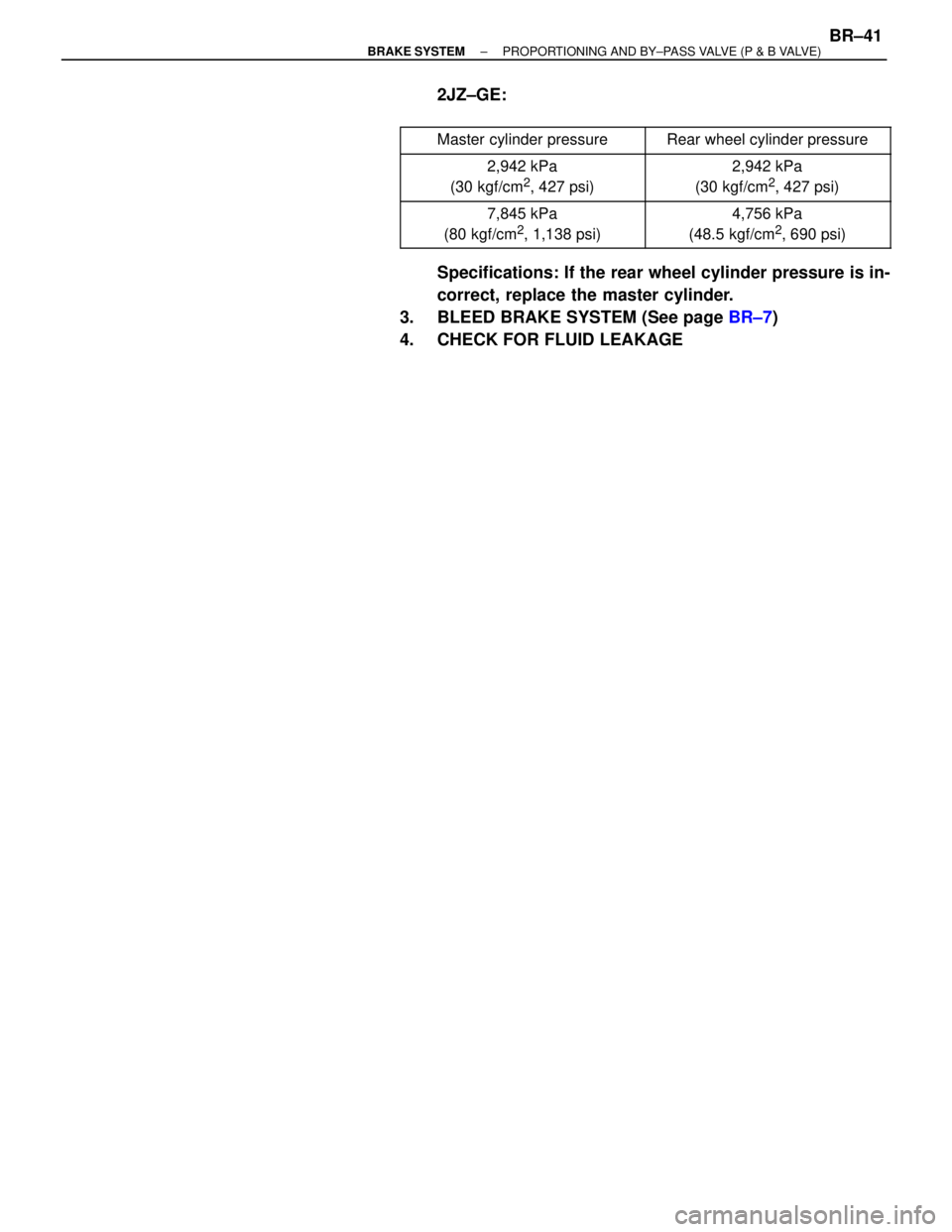
2JZ±GE:
����������� �����������Master cylinder pressure������������ ������������Rear wheel cylinder pressure
����������� �
���������� �����������
2,942 kPa
(30 kgf/cm2, 427 psi)
������������ �
����������� ������������
2,942 kPa
(30 kgf/cm2, 427 psi)
����������� �
���������� �����������
7,845 kPa
(80 kgf/cm2, 1,138 psi)
������������ �
����������� ������������
4,756 kPa
(48.5 kgf/cm2, 690 psi)
Specifications: If the rear wheel cylinder pressure is in-
correct, replace the master cylinder.
3. BLEED BRAKE SYSTEM (See page BR±7)
4. CHECK FOR FLUID LEAKAGE
± BRAKE SYSTEMPROPORTIONING AND BY±PASS VALVE (P & B VALVE)BR±41
Page 921 of 2543
P. BR±84
P. BR±86 ~ BR±89
P. BR±24
P. BR±86
P. BR±88P. BR±92
P. BR±104 ~ BR±165P. BR±166
Vehicle brought to workshop
Perform troubleshooting in accordance with the procedure on the following pages.
Items insideare titles of pages in this manual,
with the page number in the bottom portion. See the pages
for detailed explanations.
Customer Problem Analysis
Check and Clear Diagnostic Trouble Codes (Precheck)
Symptom
does not occur
Problem Symptom ConfirmationSymptom Simulation
Symptom
occurs
Diagnostic Trouble Code CheckNormal code
Malfunction code
Diagnostic Trouble Code ChartProblem Symptoms Chart
Circuit InspectionSensor CheckCheck for Fluid Leakage
Identification of Problem
Repair
Confirmation Test
EndStepDiagnostic steps permitting the use of the TOYOTA
hand±held tester or TOYOTA break±out box.
HOW TO PROCEED WITH TROUBLESHOOTING
BR±52± BRAKE SYSTEMANTI±LOCK BRAKE SYSTEM (ABS)
Page 926 of 2543

BR±88.
BR±88
BR±92
BR±95
BR±97
BR±98
BR±100
BR±102
BR±104
CodeABS Warning Light
Blinking Pattern
Indicator
DiagnosisSee pageABS
Warning
LightTRAC
Indicator
LightTRAC
OFF
Light
ON
ON
ON
ON
ON
ON
ON
ON
ON
ON
ON
ON
ON
ON
ON
ON
ON
ON
ON
ON
OFF
OFF
OFF
OFF
OFF
OFF*
OFF*
OFF*
OFF*
Always
ON
Open circuit in left front or right rear speed sensor
circuit
Open circuit in right front or left rear speed sensor
circuit
Low battery positive voltage or abnormally high
battery positive voltage
Open or short in lateral acceleration
sensor circuit
ABS pump motor is locked
Open in ABS pump motor ground
Brake fluid reservoir level low
Open circuit in TRAC pump motor circuit
TRAC ECU communication abnormal
Wheel speed sensor signal malfunction
Malfunction in ABS (& TRAC) ECU
�: Only vehicles with TRAC
*: When a malfunction causing code No. 17, 18, 55, 58, 61 or 62 is detected, the ABS warning light does
not light up, but the TRAC indicator light does. However, when checking the DTC, check the blinking
pattern of the ABS warning light.
± BRAKE SYSTEMANTI±LOCK BRAKE SYSTEM (ABS)BR±57
Page 929 of 2543
STD Voltage (V)Condition
Always
IG switch ON
IG switch ON, ABS warning light OFF
IG switch ON
IG switch ON, TRAC and TRAC OFF indicator light OFF
IG switch ON
IG switch ON, ABS")
Symbols
(Terminals No.)STD Voltage (V)Condition
Always
IG switch ON
IG switch ON, ABS warning light OFF
IG switch ON
IG switch ON, TRAC and TRAC OFF indicator light OFF
IG switch ON
IG switch ON, ABS warning light OFF
IG switch ON, ABS warning light OFF
IG switch ON, ABS warning light OFF
IG switch ON, ABS warning light OFF
IG switch ON, ABS warning light OFF
IG switch ON, TRAC and TRAC OFF indicator light OFF
IG switch ON, TRAC and TRAC OFF indicator light OFF
IG switch ON, ABS warning light ON
IG switch ON, ABS warning light OFF
IG switch ON, PKB switch ON
Fluid in M/C reservoir above MIN level.
IG switch ON, PKB switch OFF
Fluid in M/C reservoir above MIN level.
IG switch ON
Fluid in M/C reservoir above MIN level.
Stop light switch OFF
Stop light switch ON
IG switch ON, ABS warning light OFF
BATGND
GND
R±
R±
R±
R±
GND
GND
GND
GND
GND
GND
GND
GND
GND
GND
GND
GND
(A20±7)(A20±25)
(A20±24)(A20±25)
(A20±15)(A20±12)
(A20±2)(A20±12)
(A20±12)
(A20±12)
(A22±9)
(A20±25)
(A20±25)
(A22±9)
(A20±25)
(A22±9)
(A22±9)
(A22±4)
(A22±4)
(A20±25)
(A22±4)
(A22±9)
IG 1
SR
MR
TSR
TMR
SFR
SFL
SRR
SRL
AST
SMC
SRC
WA
PKB
LBL
STP
D/G
(A20±1)
(A20±14)
(A22±1)
(A20±13)
(A20±26)
(A22±7)
(A20±21)
(A22±2)
(A22±8)
(A22±5)
(A22±12)
(A20±10)
(A22±6)
(A22±10)
10 ±14
10 ±14
8.3 ±14
Below 1.0
8.3 ±14
Below 1.0
10 ±14
10 ±14
10 ±14
10 ±14
10 ±14
10 ±14
10 ±14
Below 2.0
10 ±14
Below 1.5
10 ±14
10 ±14
Below 1.5
8 ±14
10 ±14
w/ TRAC:
BR±60± BRAKE SYSTEMANTI±LOCK BRAKE SYSTEM (ABS)
Page 952 of 2543

DTC 21 22 23 24 ABS Actuator Solenoid Circuit
CIRCUIT DESCRIPTION
This solenoid goes on when signals are received from the ECU and controls the fluid pressure acting on the
brake cylinders, thus controlling the braking force.
�������� ��������DTC No.���������������� ����������������Diagnostic Trouble Code Detecting Condition������������� �������������Trouble area
�������� �
�������
��������
��������
��������
��������
��������
��������
21
����������������
����������������
����������������
����������������
����������������
����������������
���������������� ����������������
Conditions (1) through (3) continue for 0.05
sec. or more:
(1) ABS solenoid relay terminal (SR)
voltage: Battery positive voltage
(2) Voltage of ABS (& TRAC) ECU terminal
AST: Battery positive voltage
(3) When power transistor of ECU is ON,
voltage of terminal SFR is 0 V or battery
positive voltage.������������� �
������������ �
������������ �
������������ �
������������ �
������������ �
������������ �������������
� ABS actuator
� Open or short in SFR circuit.
� ECU
�������� �
�������
��������
��������
��������
��������
��������
��������
22
����������������
����������������
����������������
����������������
����������������
����������������
���������������� ����������������
Conditions (1) through (3) continue for 0.05
sec. or more:
(1) ABS solenoid relay terminal (SR)
voltage: Battery positive voltage
(2) Voltage of ABS (& TRAC) ECU terminal
AST: Battery positive voltage
(3) When power transistor of ECU is ON,
voltage of terminal SFL is 0 V or battery
positive voltage.������������� �
������������ �
������������ �
������������ �
������������ �
������������ �
������������ �������������
� ABS actuator
� Open or short in SFL circuit.
� ECU
�������� �
�������
��������
��������
��������
��������
��������
��������
��������
23
����������������
����������������
����������������
����������������
����������������
����������������
����������������
���������������� ����������������
Conditions (1) through (3) continue for 0.05
sec. or more:
(1) ABS solenoid relay terminal (SR)
voltage: Battery positive voltage
(2) Voltage of ABS (& TRAC) ECU terminal
AST: Battery positive voltage
(3) When power transistor of ECU is ON,
voltage of terminal SRR is 0 V or battery
positive voltage.
������������� �
������������ �
������������ �
������������ �
������������ �
������������ �
������������ �
������������ �������������
� ABS actuator
� Open or short in SRR circuit.
� ECU
�������� �
�������
��������
��������
��������
��������
��������
��������
24
����������������
����������������
����������������
����������������
����������������
����������������
���������������� ����������������
Conditions (1) through (3) continue for 0.05
sec. or more:
(1) ABS solenoid relay terminal (SR)
voltage: Battery positive voltage
(2) Voltage of ABS (& TRAC) ECU terminal
AST: Battery positive voltage
(3) When power transistor of ECU is ON,
voltage of terminal SRL is 0 V or battery
positive voltage.������������� �
������������ �
������������ �
������������ �
������������ �
������������ �
������������ �������������
� ABS actuator
� Open or short in SRL circuit.
� ECU
Fail safe function: If trouble occurs in the actuator solenoid circuit, the ECU cuts off current to the solenoid relay
and prohibits ABS control.
± BRAKE SYSTEMANTI±LOCK BRAKE SYSTEM (ABS)BR±83
Page 955 of 2543

DTC 25 27 TRAC Actuator Solenoid Circuit
CIRCUIT DESCRIPTION
The TRAC actuator solenoid operates in accordance with signals from the ECU and raises the fluid pressure
in and releases it from the brake cylinders.
������� �������DTC No.������������������ ������������������Diagnostic Trouble Code Detecting Condition������������� �������������Trouble area������� �
������ �
������ �
������ �
������ �������
25
������������������ �
����������������� �
����������������� �
����������������� �
����������������� ������������������
Conditions (1) and (2) continue for 0.05 sec.
or more:
(1) TRAC solenoid relay terminal (TSR)
voltage: Battery positive voltage
(2) Voltage oS & TRAC ECU terminal AB
SMC: 0 V
������������� �
������������ �
������������ �
������������ �
������������ �������������
� TRAC actuator
� Open or short in SMC circuit
� ECU
������� �
������ �
������ �
������ �
������ �
������ �������
27
������������������ �
����������������� �
����������������� �
����������������� �
����������������� �
����������������� ������������������
Conditions (1) and (2) continue for 0.05 sec.
or more:
(1) TRAC solenoid relay terminal (TSR)
voltage: Battery positive voltage
(2) Voltage of ABS & TRAC ECU terminal
SRC: 0V
������������� �
������������ �
������������ �
������������ �
������������ �
������������ �������������
� TRAC actuator
� Open or short in SRC circuit
� ECU
Fail safe function: If trouble occurs in this solenoid circuit, the ECU cuts off current to the ABS and TRAC solenoid
relays and prohibits ABS and TRAC control.
BR±86± BRAKE SYSTEMANTI±LOCK BRAKE SYSTEM (ABS)
Page 967 of 2543
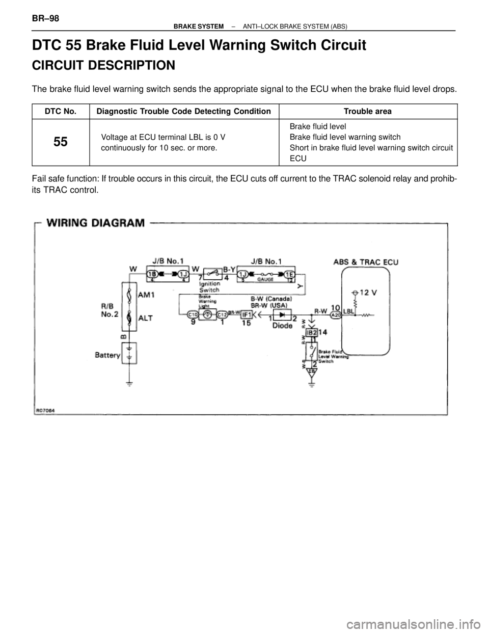
DTC 55 Brake Fluid Level Warning Switch Circuit
CIRCUIT DESCRIPTION
The brake fluid level warning switch sends the appropriate signal to the ECU when the brake fluid level drops.
������ ������DTC No.���������������� ����������������Diagnostic Trouble Code Detecting Condition���������������� ����������������Trouble area
������ �
����� �
����� �
����� ������
55
���������������� �
��������������� �
��������������� �
��������������� ����������������
Voltage at ECU terminal LBL is 0 V
continuously for 10 sec. or more.
���������������� �
��������������� �
��������������� �
��������������� ����������������
� Brake fluid level
� Brake fluid level warning switch
� Short in brake fluid level warning switch circuit
� ECU
Fail safe function: If trouble occurs in this circuit, the ECU cuts off current to the TRAC solenoid relay and prohib-
its TRAC control. BR±98
± BRAKE SYSTEMANTI±LOCK BRAKE SYSTEM (ABS)
Page 968 of 2543
Check brake fluid level.
Check brake fluid level warning switch.
Check and repair brake fluid leakage and
add fluid.
Replace brake fluid level warning switch.
Repair or replace harness or connector.
Check and replace ABS & TRAC ECU.
Check for short in all the harness and components connected to brake fluid
level warning light (See page IN±30).
See page BE±52.
Check the amount of fluid in the brake reservoir.
± BRAKE SYSTEMANTI±LOCK BRAKE SYSTEM (ABS)BR±99