Page 1251 of 2543

18. BRAKE PEDAL
(a) Check that pedal for smooth operation.
(b) Check that the pedal has the proper reserve
distance and freeplay.
(c) Check the brake booster function.
19. BRAKES
At a safe place, check that the brakes do not
pull to one side when applied.
20. PARKING BRAKE
(a) Check that the pedal has the proper travel.
(b) On a safe incline, check that the vehicle is
held securely with only the parking brake
applied.
21. AUTOMATIC TRANSMISSION PARK
MECHANISM
(a) Check the lock release button of the selector
lever for proper and smooth operation.
(b) On a safe incline, check that the vehicle is
held securely with the selector lever in the ºPº
position and all brakes released.
UNDER HOOD
22. WINDSHIELD WASHER FLUID
Check that there is sufficient fluid in the tank.
23. ENGINE COOLANT LEVEL
Check that the coolant level is between the
LEVEL lines on the see±through reservoir at
normal temperature (20°C (68°F)).
24. RADIATOR AND HOSES
(a) Check that the front of the radiator is clean
and not blocked with leaves, dirt or bugs.
(b) Check the hoses for cracks, kinks, rot or
loose connections.
25. BATTERY ELECTROLYTE LEVEL
Check the indicator.
When the indicator color is blue, the condition
is satisfactory. A red color indicates that dis-
tilled water must be added, and white indi-
cates that charging is necessary.
26. BRAKE FLUID LEVEL
Check that the brake fluid level is near the up-
per level line on the see±through reservoir.27. ENGINE DRIVE BELT
Check drive belt for fraying, cracks, wear or
oil contamination.
28. ENGINE OIL LEVEL
Check that level on the dipstick with the en-
gine turned off.
29. POWER STEERING FLUID LEVEL
Check the level on the dipstick.
The level should be in the ºHOTº or ºCOLDº
range depending on the fluid temperature.
30. A U TO M AT I C TRANSMISSION FLUID
LEVEL
(a) Park the vehicle on a level surface.
(b) With the engine idling and the parking and
foot brake applied, shift the selector into all
positions from ºPº to ºLº, and then shift into ºPº
position.
(c) Turn and pull out the dipstick and wipe off the
fluid with a clean rag.
Re±insert the dipstick fully and check that the
fluid level is in the ºHOTº range.
(d) Perform this check with the fluid at normal
driving temperature (70±80°C (158±176°F)).
If the level is at the low side, add fluid.
NOTICE: Do not overfill.
HINT: Wait about 30 minutes before checking
the fluid level after extended driving at high
speeds in hot weather, driving in heavy traffic
or with a trailer.
31. EXHAUST SYSTEM
Visually inspect for cracks, holes or loose
supports.
If any change in the sound of the exhaust or
smell of the exhaust fumes is noticed, have
the cause located and correted. MA±18
± MAINTENANCEGENERAL MAINTENANCE
Page 1392 of 2543

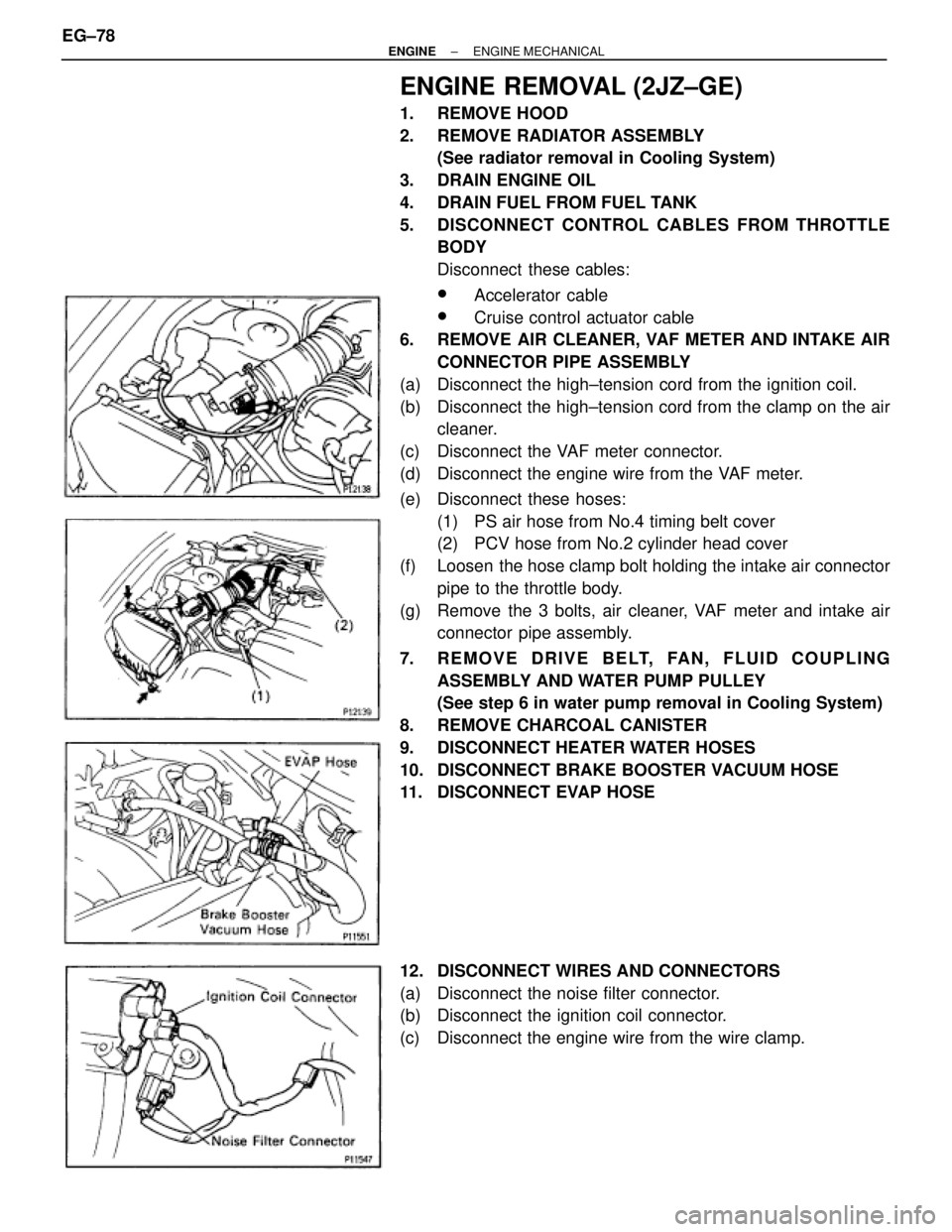
ENGINE REMOVAL (2JZ±GE)
1. REMOVE HOOD
2. REMOVE RADIATOR ASSEMBLY
(See radiator removal in Cooling System)
3. DRAIN ENGINE OIL
4. DRAIN FUEL FROM FUEL TANK
5. DISCONNECT CONTROL CABLES FROM THROTTLE
BODY
Disconnect these cables:
wAccelerator cable
wCruise control actuator cable
6. REMOVE AIR CLEANER, VAF METER AND INTAKE AIR
CONNECTOR PIPE ASSEMBLY
(a) Disconnect the high±tension cord from the ignition coil.
(b) Disconnect the high±tension cord from the clamp on the air
cleaner.
(c) Disconnect the VAF meter connector.
(d) Disconnect the engine wire from the VAF meter.
(e) Disconnect these hoses:
(1) PS air hose from No.4 timing belt cover
(2) PCV hose from No.2 cylinder head cover
(f) Loosen the hose clamp bolt holding the intake air connector
pipe to the throttle body.
(g) Remove the 3 bolts, air cleaner, VAF meter and intake air
connector pipe assembly.
7. REMOVE DRIVE BELT, FAN, FLUID COUPLING
ASSEMBLY AND WATER PUMP PULLEY
(See step 6 in water pump removal in Cooling System)
8. REMOVE CHARCOAL CANISTER
9. DISCONNECT HEATER WATER HOSES
10. DISCONNECT BRAKE BOOSTER VACUUM HOSE
11. DISCONNECT EVAP HOSE
12. DISCONNECT WIRES AND CONNECTORS
(a) Disconnect the noise filter connector.
(b) Disconnect the ignition coil connector.
(c) Disconnect the engine wire from the wire clamp. EG±78
± ENGINEENGINE MECHANICAL
Page 1399 of 2543

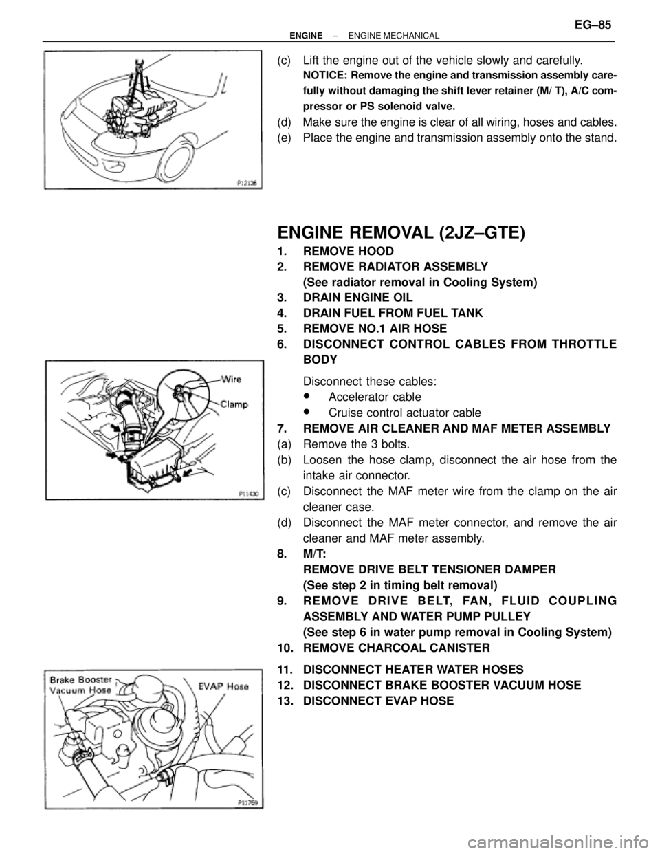
(c) Lift the engine out of the vehicle slowly and carefully.
NOTICE: Remove the engine and transmission assembly care-
fully without damaging the shift lever retainer (M/ T), A/C com-
pressor or PS solenoid valve.
(d) Make sure the engine is clear of all wiring, hoses and cables.
(e) Place the engine and transmission assembly onto the stand.
ENGINE REMOVAL (2JZ±GTE)
1. REMOVE HOOD
2. REMOVE RADIATOR ASSEMBLY
(See radiator removal in Cooling System)
3. DRAIN ENGINE OIL
4. DRAIN FUEL FROM FUEL TANK
5. REMOVE NO.1 AIR HOSE
6. DISCONNECT CONTROL CABLES FROM THROTTLE
BODY
Disconnect these cables:
wAccelerator cable
wCruise control actuator cable
7. REMOVE AIR CLEANER AND MAF METER ASSEMBLY
(a) Remove the 3 bolts.
(b) Loosen the hose clamp, disconnect the air hose from the
intake air connector.
(c) Disconnect the MAF meter wire from the clamp on the air
cleaner case.
(d) Disconnect the MAF meter connector, and remove the air
cleaner and MAF meter assembly.
8. M/T:
REMOVE DRIVE BELT TENSIONER DAMPER
(See step 2 in timing belt removal)
9. REMOVE DRIVE BELT, FAN, FLUID COUPLING
ASSEMBLY AND WATER PUMP PULLEY
(See step 6 in water pump removal in Cooling System)
10. REMOVE CHARCOAL CANISTER
11. DISCONNECT HEATER WATER HOSES
12. DISCONNECT BRAKE BOOSTER VACUUM HOSE
13. DISCONNECT EVAP HOSE
± ENGINEENGINE MECHANICALEG±85
Page 1442 of 2543

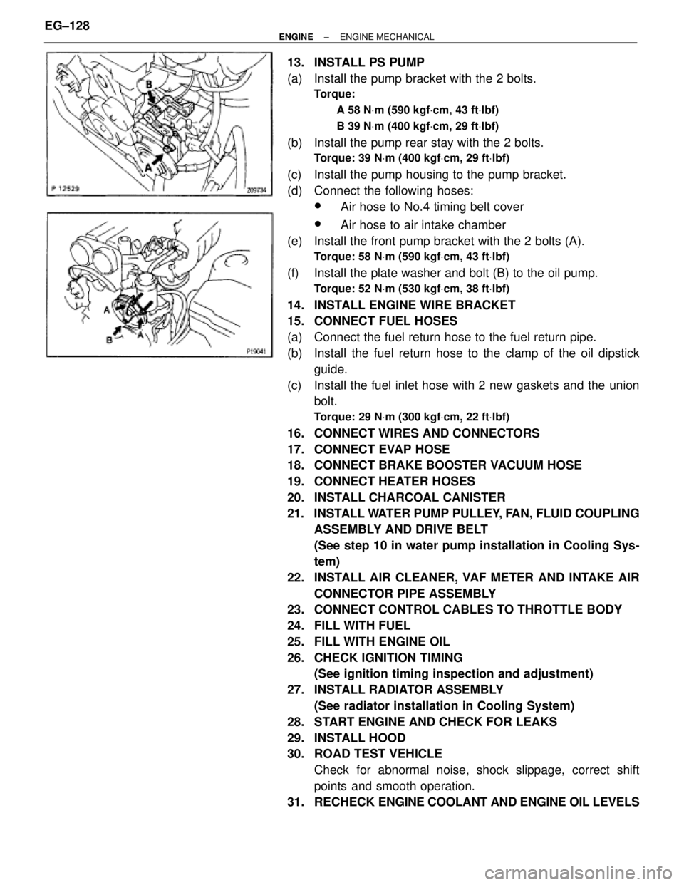
13. INSTALL PS PUMP
(a) Install the pump bracket with the 2 bolts.
Torque:
A 58 NVm (590 kgfVcm, 43 ftVlbf)
B 39 NVm (400 kgfVcm, 29 ftVlbf)
(b) Install the pump rear stay with the 2 bolts.
Torque: 39 NVm (400 kgfVcm, 29 ftVlbf)
(c) Install the pump housing to the pump bracket.
(d) Connect the following hoses:
wAir hose to No.4 timing belt cover
wAir hose to air intake chamber
(e) Install the front pump bracket with the 2 bolts (A).
Torque: 58 NVm (590 kgfVcm, 43 ftVlbf)
(f) Install the plate washer and bolt (B) to the oil pump.
Torque: 52 NVm (530 kgfVcm, 38 ftVlbf)
14. INSTALL ENGINE WIRE BRACKET
15. CONNECT FUEL HOSES
(a) Connect the fuel return hose to the fuel return pipe.
(b) Install the fuel return hose to the clamp of the oil dipstick
guide.
(c) Install the fuel inlet hose with 2 new gaskets and the union
bolt.
Torque: 29 NVm (300 kgfVcm, 22 ftVlbf)
16. CONNECT WIRES AND CONNECTORS
17. CONNECT EVAP HOSE
18. CONNECT BRAKE BOOSTER VACUUM HOSE
19. CONNECT HEATER HOSES
20. INSTALL CHARCOAL CANISTER
21. INSTALL WATER PUMP PULLEY, FAN, FLUID COUPLING
ASSEMBLY AND DRIVE BELT
(See step 10 in water pump installation in Cooling Sys-
tem)
22. INSTALL AIR CLEANER, VAF METER AND INTAKE AIR
CONNECTOR PIPE ASSEMBLY
23. CONNECT CONTROL CABLES TO THROTTLE BODY
24. FILL WITH FUEL
25. FILL WITH ENGINE OIL
26. CHECK IGNITION TIMING
(See ignition timing inspection and adjustment)
27. INSTALL RADIATOR ASSEMBLY
(See radiator installation in Cooling System)
28. START ENGINE AND CHECK FOR LEAKS
29. INSTALL HOOD
30. ROAD TEST VEHICLE
Check for abnormal noise, shock slippage, correct shift
points and smooth operation.
31. RECHECK ENGINE COOLANT AND ENGINE OIL LEVELS EG±128
± ENGINEENGINE MECHANICAL
Page 1445 of 2543

13. CONNECT ENGINE WIRE TO COWL PANEL
14. INSTALL A/C COMPRESSOR
(a) Using a torx socket (E10), install the stud bolt and and
compressor.
Torque: 26 NVm (265 kgfVcm, 19 ftVlbf)
(b) Connect the compressor connector.
(c) Temporarily install the compressor with nut and 3 bolts.
(d) Alternately tighten the bolt and nut.
Torque: 52 NVm (530 kgfVcm, 38 ftVlbf)
15. INSTALL PS PRESSURE TUBE
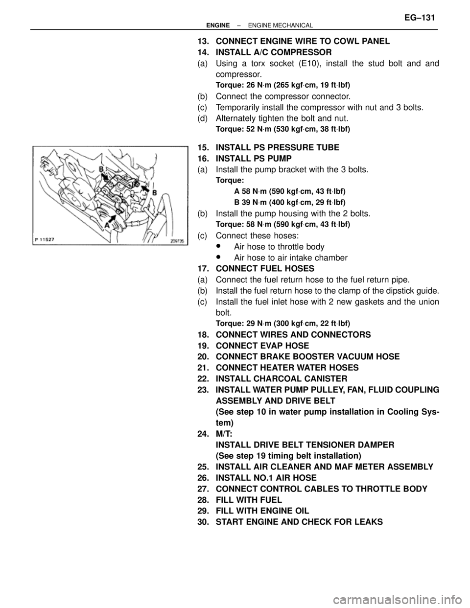
16. INSTALL PS PUMP
(a) Install the pump bracket with the 3 bolts.
Torque:
A 58 NVm (590 kgfVcm, 43 ftVlbf)
B 39 NVm (400 kgfVcm, 29 ftVlbf)
(b) Install the pump housing with the 2 bolts.
Torque: 58 NVm (590 kgfVcm, 43 ftVlbf)
(c) Connect these hoses:
wAir hose to throttle body
wAir hose to air intake chamber
17. CONNECT FUEL HOSES
(a) Connect the fuel return hose to the fuel return pipe.
(b) Install the fuel return hose to the clamp of the dipstick guide.
(c) Install the fuel inlet hose with 2 new gaskets and the union
bolt.
Torque: 29 NVm (300 kgfVcm, 22 ftVlbf)
18. CONNECT WIRES AND CONNECTORS
19. CONNECT EVAP HOSE
20. CONNECT BRAKE BOOSTER VACUUM HOSE
21. CONNECT HEATER WATER HOSES
22. INSTALL CHARCOAL CANISTER
23. INSTALL WATER PUMP PULLEY, FAN, FLUID COUPLING
ASSEMBLY AND DRIVE BELT
(See step 10 in water pump installation in Cooling Sys-
tem)
24. M/T:
INSTALL DRIVE BELT TENSIONER DAMPER
(See step 19 timing belt installation)
25. INSTALL AIR CLEANER AND MAF METER ASSEMBLY
26. INSTALL NO.1 AIR HOSE
27. CONNECT CONTROL CABLES TO THROTTLE BODY
28. FILL WITH FUEL
29. FILL WITH ENGINE OIL
30. START ENGINE AND CHECK FOR LEAKS
± ENGINEENGINE MECHANICALEG±131