Page 2050 of 2543
(See page EG±321)
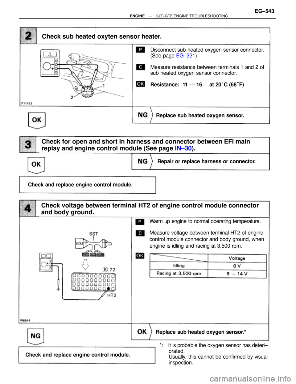
Disconnect sub heated oxygen sensor connector.
(See page EG±321)
Measure resistance between terminals 1 and 2 of
sub heated oxygen sensor connector.
Resistance: 11 Ð 16 � at 20°C (68°F)
Check for open and short in harness and connector between EFI main
replay and engine control module (See page IN±30).
Check sub heated oxyten sensor heater.
Replace sub heated oxygen sensor.
Repair or replace harness or connector.
Check and replace engine control module.
Check voltage between terminal HT2 of engine control module connector
and body ground.
Replace sub heated oxygen sensor.*
Check and replace engine control module.
Warm up engine to normal operating temperature.
Measure voltage between terminal HT2 of engine
control module connector and body ground, when
engine is idling and racing at 3,500 rpm.
*: It is probable the oxygen sensor has deteri±
orated.
Usually, this cannot be confirmed by visual
inspection.
± ENGINE2JZ±GTE ENGINE TROUBLESHOOTINGEG±543
Page 2051 of 2543

DTC 31 Mass Air Flow Meter Circuit
CIRCUIT DESCRIPTION
The mass air flow meter is an air flow meter which uses a platinum hot wire. The hot wire air flow meter
works on the principle that when the electrically heated platinum hot wire is positioned inside the intake
air bypass, the intake air volume can be calculated according to the change in the hot wire temperature.
This change in temperature is measured by the thermistor at the rear of the hot wire. And feedback from
the circuit maintains the hot wire at a set temperature by controlling the current flowing through the hot
wire. This current flow is then measured as the output voltage of the air flow meter. The circuit is
constructed so that the platinum hot wire and the thermistor provide a bridge circuit, with the power transis-
tor controlled so that the potential of (A) or (B) remains equal to maintain the set temperature.
�Open or short in mass air flow master
circuit
�Mass air flow meter
�ECM
Open or short in mass air flow meter circuit for
3 sec. or more with engine speed less than
3,000 rpm
If the ECM detects diagnostic trouble code ª31º, it operates the fail safe function whereby the turbo
pressure sensor is used, making it possible to continue to drive the vehicle. EG±544
± ENGINE2JZ±GTE ENGINE TROUBLESHOOTING
Page 2056 of 2543

Sensor Circuit
CIRCUIT DESCRIPTION
HINT DTC 35 is used to indicate malfunctions in the turbo pressure sensor circuit or BARO sensor c")
DTC 35 Turbo Pressure Sensor Circuit Barometric Pressure (BARO)
Sensor Circuit
CIRCUIT DESCRIPTION
HINT DTC 35 is used to indicate malfunctions in the turbo pressure sensor circuit or BARO sensor circuit.
1. TURBO PRESSURE SENSOR
This sensor detects the air intake chamber pressure and converts the pressure reading into a voltage which
is used to control the turbo pressure by the ECM.
If the ECM detects the below diagnosis conditions, it operates the fail safe function in which the ECM stops
fuel injection at engine speed 2,400 rpm or more and throttle opening angle 20° or more.
����� �
���� �����DTC No.����� �
���� �����Circuit����������������� �
���������������� �����������������Diagnostic Trouble Code Detecting Condition������������ �
����������� ������������Trouble Area
����� �
���� �
���� �
���� �����
35
����� �
���� �
���� �
���� �����
Turbo
Pressure
Sensor����������������� �
���������������� �
���������������� �
���������������� �����������������
Open or short in turbo pressure sensor
circuit for 0.5 sec. or more
������������ �
����������� �
����������� �
����������� ������������
�Open or short in turbo
pressure sensor circuit
�Turbo pressure sensor
�ECM
2. BARO SENSOR
This sensor is built into the ECM. It is used to detect the atmospheric (absolute) pressure and outputs corre-
sponding electrical signals. Fluctuations in the air pressure cause changes in the intake air density which
can cause deviations in the air±fuel ratio. The signals from BARO sensor are used to make corrections for
the fluctuations. If the ECM detects the below diagnosis conditions, it operates the fail safe function in which
the atmospheric pressure is assumed to be 101.3 kPa (1.03 kgf/cm
2, 14.7 psi).
����� �����DTC No.����� �����Circuit����������������� �����������������Diagnostic Trouble Code Detecting Condition������������ ������������Trouble Area����� �
���� �
���� �
���� �
���� �
���� �����
35
����� �
���� �
���� �
���� �
���� �
���� �����
BARO
Sensor
����������������� �
���������������� �
���������������� �
���������������� �
���������������� �
���������������� �����������������
Open or short in BARO sensor circuit for
0.5 sec. or more
������������ �
����������� �
����������� �
����������� �
����������� �
����������� ������������
� ECM
± ENGINE2JZ±GTE ENGINE TROUBLESHOOTINGEG±549
Page 2057 of 2543
(See page EG±510)(1) Connect SST (check harness ªAº).
(See page EG±510)
SST 09990±01000
(2) Turn ignition switch ON.
Measure voltage between terminals VCC and E1
of engine control module.
Voltage: 4.5 Ð 5.5 V
Check voltage between terminals VCC and E1 of engine control module
connector.
Check and replace engine control module.
INSPECTION PROCEDURE
HINT: DTC 35 indicates trouble in the BARO sensor circuit or turbo pressure sensor circuit. Because all func±
tions of the BARO sensor circuit are built into the ECM, it is not possible to check this circuit.
However, if no problem is found in the turbo pressure sensor circuit, it can be concluded that the problem
is in the BARO sensor circuit. EG±550
± ENGINE2JZ±GTE ENGINE TROUBLESHOOTING
Page 2058 of 2543
(See page IN±30).
Turn ignition switch ON.
Measure voltage between terminals PM1 and E2
of engine control module.
Voltage: 2.3 Ð 3.0 V
Check voltage between terminals PM1 and E2 of engine control module.
Check for open and short in harness and connector between engine control
module and turbo pressure sensor (See page
IN±30).
Check and replace engine control module.
Repair or replace harness or connector.
Replace turbo pressure sensor.
± ENGINE2JZ±GTE ENGINE TROUBLESHOOTINGEG±551
Page 2059 of 2543

CIRCUIT DESCRIPTION
The throttle position sensor is mounted in the throttle
body and detects the the throttle valve opening angle.
When the throttle valve is fully closed, the IDL contacts
in the throttle position sensor are on, so the voltage at
the terminal IDL of the ECM becomes 0 V. At this time,
a voltage of approximately 0.7 V is applied to the termi-
nal VTA of the ECM. When the throttle valve is opened,
the IDL contacts go off and thus the power source volt-
age of approximately 12 V in the ECM is applied to the
terminal IDL of the ECM. The voltage applied to the ter-
minal VTA of the ECM increases in the proportion to
the opening angle of the throttle valve and becomes
approximately 3.2 ± 4.9 V when the throttle valve is ful-
ly opened. The ECM judges the vehicle driving condi-
tions from these signals input from the terminals VTA
and IDL, and uses them as one of the conditions for de-
ciding the air±fuel ratio correction, power increase
corrections and fuel±cut control etc. The sub±throttle
position sensor is built and operates in the same way
as the main throttle position sensor. This sensor is
used for traction control. The sub±throttle valve is
opened and closed by the sub±throttle actuator ac-
cording to signals from the TRAC ECU to control the
engine output.
Open or short in throttle position sensor circuit
for 0.5 sec. or more
Open or short in sub±throttle position sensor
circuit for 0.5 sec. or more
�Open or short in throttle position sensor
circuit
�Throttle position sensor
�ECM
�Open or short in sub±throttle position
sensor circuit
�Sub±throttle position sensor
�ECM
HINT:
Diagnostic trouble code 41 is for the throttle position sensor circuit.
Diagnostic trouble code 47 is for the sub±throttle position sensor circuit.
�When the connector for the throttle position sensor(s) is disconnected, diagnostic trouble code 41
or 47 is not displayed. Diagnostic trouble code 41 or 47 is displayed only when there is an open
or short in the VTA signal circuit of the throttle position sensor(s).
�Signals from the throttle position sensor(s) are also input to the TRAC ECU, so when a malfunc±
tion occurs on the TRAC side, code 41 or 47 may be displayed.
DTC 41 47 Throttle Position Sensor(s) Circuit
EG±552± ENGINE2JZ±GTE ENGINE TROUBLESHOOTING
Page 2061 of 2543

INSPECTION PROCEDURE
HINT:
wIf diagnostic trouble code 41 is displayed, check throttle position sensor circuit. If diagnostic trouble code
47 is displayed, check sub±throttle position sensor circuit.
wIf diagnostic trouble code º22º (engine coolant temperature sensor circuit), º24º (intake air temperature
sensor circuit) and º41º (throttle position sensor circuit) are output simultaneously. E2 (sensor ground) may
be open.
(See page EG±505)
(See page EG±510)
(See page EG±292)
Check voltage between terminals VTA1, 2, IDL1, 2 and E2 of engine control
module connector.
The voltage should increase steadily in proportion
to the throttle valve opening angle.
(1) Connect SST (check harness ªAº).
(See page EG±510)
SST 09990±01000
(2) Turn ignition switch ON.
(3) For throttle position sensor, disconnect the vacuum
hose from the throttle body, then apply vacuum to
the throttle opener.
(See page EG±292)
(4) For sub±throttle position sensor, remove intake air
duct and disconnect sub±throttle valve step motor
connector.
Measure voltage between terminals VTA1, 2, IDL1,
2 and E2 of engine control module connector when
the (sub±) throttle valve is opened gradually from
the closed condition.
Check for intermittent problems.
(See page
EG±505)
Throttle Valve
Terminal
Fully Closed
Fully Open
EG±554± ENGINE2JZ±GTE ENGINE TROUBLESHOOTING
Page 2062 of 2543
(1) Remove throttle body. (See page EG±291)
(2) For throttle position sensor, apply vacuum to
throttle opener. (See page
EG±292)
Measure resistance of each terminal as below table
when the throttle valve is opened gradually from the
closed condition.
Check throttle position sensor(s).
Check for open and short in harness and connector between engine control
module and throttle position sensors(s) (See page
IN±30).
Resistance between terminals 2,3 (VTA1,2) and 4,1
(E2) should increase gradually in accordance with
the throttle valve opening angle.
Adjust or replace throttle position sensor(s).
(See page EG±292)
Repair or replace harness or connector.
Check and replace engine control module.
For Throttle Position Sensor
For Sub±Throttle Position Sensor
Throttle Valve
Terminal
Throttle
Position
Sensor
Sub throttle
Position
Sensor
Fully
Closed Fully
Opened
± ENGINE2JZ±GTE ENGINE TROUBLESHOOTINGEG±555
(1) Connect SST (check harness ªAº).
(See page EG±510)
SST 09990±01000
(2) Turn ignition switch ON.
Measure voltage between terminals VCC and E1
of engine control module.
Voltage")
.
Turn ignition switch ON.
Measure voltage between terminals PM1 and E2
of engine control module.
Voltage: 2.3 Ð 3.0 V
Check voltage between terminals PM1 and E2 of engine control m")
 Remove throttle body. (See page EG±291)
(2) For throttle position sensor, apply vacuum to
throttle opener. (See page
EG±292)
Measure resistance of each terminal as below table
when the throttle")