Page 2063 of 2543

DTC 42 No. 1 Vehicle Speed Sensor Signal Circuit
CIRCUIT DESCRIPTION
The No.1 vehicle speed sensor outputs a 4±pulse signal for every revolution of the rotor shaft, which
is rotated by the transmission output shaft via the driven gear. After this signal is converted into a more
precise rectangular waveform by the waveform shaping circuit inside the odometer and trip meter, it is
then transmitted to the engine control module. The ECM determines the vehicle speed based on the
frequency of these pulse signals.
DTC No.Diagnostic Trouble Code Detecting ConditionTrouble Area
For A/T
All conditions below are detected
Continuously for 8 sec. or more:
(a) No.1 vehicle speed signal: 0 km/h
(mph)
(b) Engine speed: 3,000 rpm or more
(c) Park/neutral position switch: OFF
(d) Stop light switch: OFF
For A/T
All conditions below are detected
Continuously for 8 sec. or more:
(a) No.1 vehicle speed signal: 0 km/h
(mph)
(b) Engine speed: Between 1,500 rpm
and 4,000 rpm
(c) Engine coolant temp.: 80°C (176°F)
or more
(d) Load driving
�No.1 vehicle speed sensor
�Telltale light RH (Odometer and trip meter)
�Open or short in No.1 vehicle speed sensor
circuit
�ECM
HINT: In test mode, diagnostic trouble code 42 is output when vehicle speed is 5 km/h (3 mph) or
below.
�Waveform between terminals SP1 and E1 when vehicle
speed is approx. 20 km/h (12mph).
HINT: As the vehicle speed increases, the number of signals
from SP1 increases. EG±556
± ENGINE2JZ±GTE ENGINE TROUBLESHOOTING
Page 2065 of 2543
INSPECTION PROCEDURE
(See page EG±510)
(1) Shift the shift lever to N position.
(2) Jack up one of the rear wheels.
(3) Connect SST (check harness ªAº).
(See page
EG±510)
(4) Disconnect power steering ECU connector
and cruise control ECU connector.
(5) Turn ignition switch ON.
Measure voltage between terminal SP1 of engine
control module connector and body ground when
the wheel is turned slowly.
Voltage is generated intermittently.
Check voltage between terminal SP1 of engine control module connector
and body ground.
Check and replace engine control module.
Repair or replace harness or connector between
ECM and telltale light RH.
Repair or replace harness or connector between
telltale light RH and No.1 vehicle speed sensor.
Replace No.1 vehicle speed sensor.
Check operation of odometer and trip meter (telltale light RH
(See page Be±48)).
Check operation of No.1 vehicle speed sensor (See page BE±46).
EG±558± ENGINE2JZ±GTE ENGINE TROUBLESHOOTING
Page 2068 of 2543

DTC 52 53 55 Knock Sensor Circuit
CIRCUIT DESCRIPTION
Knock sensors are fitted one each to the front and rear of the left side of the cylinder block to detect
engine knocking. This sensor contains a piezoelectric element which generates a voltage when it be-
comes deformed, which occurs when the cylinder block vibrates due to knocking. If engine knocking
occurs, ignition timing is retarding to suppress it.
DTC No.Diagnostic Trouble Code Detecting ConditionTrouble Area
No No.1 knock sensor signal to ECM for 4
crank revolutions with engine speed between
2,050 rpm and 5,950 rpm
Engine control computer (for knock control)
malfunction at engine speed between 650 rpm
and 5,200 rpm
No No.2 knock sensor signal to ECM for 4
crank revolutions with engine speed between
2,050 rpm and 5,950 rpm
�Open or short in No.1 knock sensor circuit
�No.1 knock sensor (Looseness)
�ECM
�ECM
�Open or short No.2 knock sensor circuit
�No.2 knock sensor (looseness)
�ECM
If the ECM detects the above diagnosis conditions, it operates the fail safe function in which the cor-
rective retard angle value is set to the maximum value.
Purpose of the driving pattern.
(a) To simulate diagnostic trouble code detecting condition after diagnostic trouble code is recorded.
(b) To check that the malfunction is corrected when the repair is completed by confirming that diagnos±
tic trouble code is no longer detected.
DIAGNOSTIC TROUBLE CODE DETECTION DRIVING PATTERN
Malfunction: Open or short in Knock Sensor
(1) Start the engine and warm up.
(2) Idle the engine for 3 min.
(3) With the A/C ON, race the engine quickly to 5,000 rpm 3 times.
(Rapidly depress the accelerator pedal and suddenly release it.)
HINT: If a malfunction exists, the malfunction indicator lamp will light up when sudden racing is
performed.
NOTICE: If the conditions in this test are not strictly followed, detection of the malfunction
will not be possible.
± ENGINE2JZ±GTE ENGINE TROUBLESHOOTINGEG±561
Page 2069 of 2543
INSPECTION PROCEDURE
HINT: If diagnostic trouble code 52 is displayed, check No.1 knock sensor (for front side) circuit.
If diagnostic trouble code 55 is displayed, check No.2 knock sensor (for rear side) circuit.
If diagnostic trouble code 53 is displayed, replace engine control module.
(See page EG±510)
(1) Connect SST (check harness ªAº).
(See page EG±510)
SST 09990±01000
(2) Disconnect the engine control module con±
nectors.
Measure resistance between terminals KNK1,
KNK2 of engine control module connector and
body ground.
Resistance: 1 M� or higher
Check continuity between terminals KNK1, KNK2 of engine control module
connector and body ground.
EG±562± ENGINE2JZ±GTE ENGINE TROUBLESHOOTING
Page 2070 of 2543
 measure
waveform between terminals KNK1, KNK2 of
engine cotrol module and body ground.
HINT: The correct waveform is as shown.
�Spread the time on the horizontal a")
�With the engine racing (4,000 rpm) measure
waveform between terminals KNK1, KNK2 of
engine cotrol module and body ground.
HINT: The correct waveform is as shown.
�Spread the time on the horizontal axis, and con
firm that the period of the wave is 123 � sec.
(Normal mode vibration frequency of knock
sensor: 8.1 KHz).
HINT: If normal mode vibration frequency is not 8.1 KHz,
the sensor is malfunctioning.
(See page EG±316)
(See page IN±30.)
(See page EG±316)
Disconnect knock sensor connector.
Measure resistance between the knock sensor terminal
and body.
Resistance: 1 M� or higher
Check knock sensor.
Replace knock sensor (See page EG±316)
Check for open and short in harness and connector between engine control
module and knock sensor (See page IN±30).
Repair or replace harness or connector.
Does malfunction disappear when a good knock sensor is installed?
Replace knock sensor. (See page EG±316)
Check and replace engine control module.
± ENGINE2JZ±GTE ENGINE TROUBLESHOOTINGEG±563
Page 2071 of 2543

See page EG±503.
CIRCUIT DESCRIPTION
The EGR system is designed to recirculate the exhaust gas, controlled according to the driving condi-
tions back into the intake air±fuel mixture. It helps to slow down combustion in the cylinder and thus
lower the combustion temperature which, in turn, reduces the amount of NO
x emission. The amount
of EGR is regulated by the EGR vacuum modulator according to the engine load.
If even one of the following conditions is fulfilled,
the VSV is turned ON by a signal from the ECM.
This resists in atmospheric air acting on the EGR
valve, closing the EGR valve and shutting off the
exhaust gas (EGR cut±OFF).
� Engine coolant temp. below 50°C (122°F)
� During deceleration (throttle valve closed)
� Light engine load (amount of intake air very
small)
� Engine speed over 4,800 rpm
� Manifold absolute pressure more than 120 kPa
(1.2 kgf/cm
2, 17.4 psi)
DTC No.Diagnostic Trouble Code Detecting ConditionTrouble Area
No No.1 knock sensor signal to ECM for 4
crank revolutions with engine speed between
2,050 rpm and 5,950 rpm
�Open EGR gas temp. sensor circuit
�Short in VSV circuit for EGR
�EGR hose disconnected, valve stuck
�Clogged EGR gas passage
�ECM
EGR gas temp. and intake air temp. are
60°C(140°F) or less for A/T, 55°C (131°F) or
less for M/T for 1 ~ 4 min. under conditions (a)
and (b):
(2 trip detection logic)*
(a) Engine coolant temp.: 60°C (140°F) or
more
(b) EGR operation possible (Example A/T in
3rd speed (5th for M/T), A/C ON, 96 km/h
(60 mph), Flat road)
Purpose of the driving pattern.
(a) To simulate diagnostic trouble code detecting condition after diagnostic trouble code is recorded.
(b) To check that the malfunction is corrected when the repair is completed by confirming that diagnos±
tic trouble code is no longer detected.
DIAGNOSTIC TROUBLE CODE DETECTION DRIVING PATTERN
DTC 71 EGR System Malfunction
EG±564± ENGINE2JZ±GTE ENGINE TROUBLESHOOTING
Page 2072 of 2543
Malfunction: Open in EGR Gas Temp. Sensor Circuit
(1) Disconnect the EFI No.1 fuse (30A) for 10 sec. or more, with IG switch OFF.
Initiate test mode (Connect terminal TE2 and E1 of data link connector 2 with IG
switch OFF).
(2) Start the engine and warm up.
(3) Idle the engine for 3 min.
(4) With the A/C ON and transmission in 5th position (A/T in 3rd speed) drive at 88 96
km/h (55 60 mph) for 4 min or less.
HINT: If a malfunction exists, the malfunction indicator lamp will light up during step (4).
NOTICE: If the conditions in this test are not strictly followed, detection of the malfunction
will not be possible.
± ENGINE2JZ±GTE ENGINE TROUBLESHOOTINGEG±565
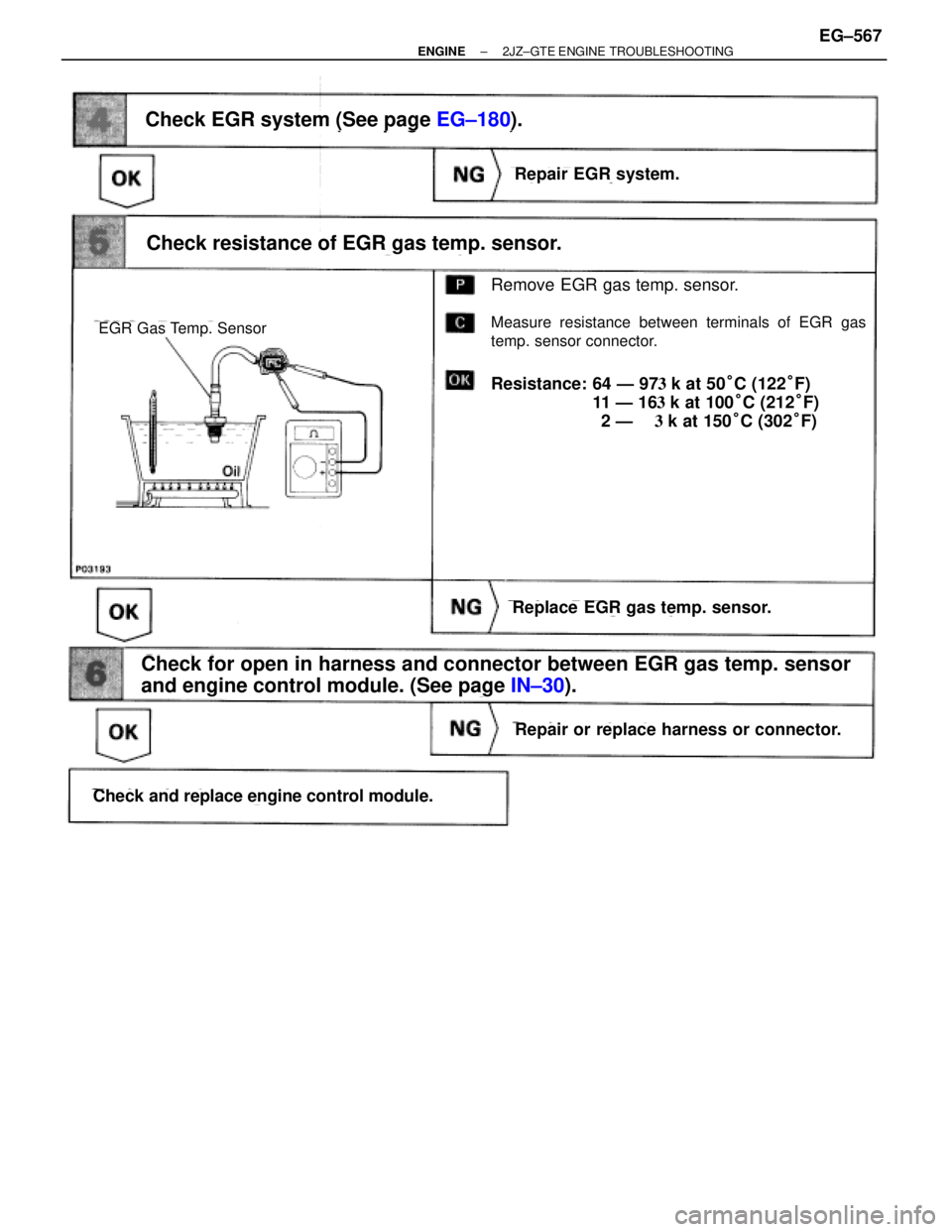
Page 2074 of 2543
(See page EG±180).
Remove EGR gas temp. sensor.
Measure resistance between terminals of EGR gas
temp. sensor connector.
Resistance: 64 Ð 97�k at 50°C (122°F)
11 Ð 1 6�k at 100°C (212°F)
2 Ð ��k at 150°C (302°F)
Check EGR system (See page EG±180).
Repair EGR system.
Check resistance of EGR gas temp. sensor.
Replace EGR gas temp. sensor.
Repair or replace harness or connector.
Check and replace engine control module.
Check for open in harness and connector between EGR gas temp. sensor
and engine control module. (See page IN±30).
EGR Gas Temp. Sensor
± ENGINE2JZ±GTE ENGINE TROUBLESHOOTINGEG±567

(1) Shift the shift lever to N position.
(2) Jack up one of the rear wheels.
(3) Connect SST (check harness ªAº).
(See page
EG±510)
(4) Disconnect power st")
 circuit.
If diagnostic trouble code 55 is displayed, check No.2 knock sensor (for rear s")
 Disconnect the EFI No.1 fuse (30A) for 10 sec. or more, with IG switch OFF.
Initiate test mode (Connect terminal TE2 and E1 of data link connector")