Page 908 of 2543

8. ADJUST PARKING BRAKE SHOE CLEARANCE")
HINT: If there are no matchmarks, temporarily install the disc,
then measure the disc runout and install the disc in the posi-
tion.
(See page BR±30 or BR±34)
8. ADJUST PARKING BRAKE SHOE CLEARANCE
(a) Temporarily install the hub nuts.
(b) Remove the hole plug.
(c) Turn the adjuster and expand the shoes until the disc locks.
(d) Return the adjuster 8 notches.
(e) Install the hole plug.
9. INSTALL REAR DISC BRAKE ASSEMBLY
Install the disc brake assembly and torque the 2 mounting
bolts.
Torque: 104 NVm (1,065 kgfVcm, 77 ftVlbf)
10. INSTALL REAR WHEEL
11. SETTLING PARKING BRAKE SHOES AND DISC
(a) Drive the vehicle at about 50 km/h (31mph) on a safe, level
and dry road.
(b) With the parking brake release button pushed in, pull on the
lever with 88 N (9 kgf, 19.8 lbf) of force.
(c) Drive the vehicle for about 400 meters (0.25 mile) in this
condition.
(d) Repeat this procedure 2 or 3 times.
12. CHECK AND ADJUST PARKING BRAKE LEVER TRAVEL
± BRAKE SYSTEMREAR BRAKE (Parking Brake)BR±39
Page 909 of 2543
PROPORTIONING AND BY±PASS
VALVE (P & B VALVE)
FLUID PRESSURE INSPECTION
1. INSTALL LSPV GAUGE (SST) AND BLEED AIR
SST 09709±29017
2. RAISE MASTER CYLINDER PRESSURE AND CHECK
REAR WHEEL CYLINDER PRESSURE
2JZ±GTE:
����������� �����������Master cylinder pressure������������ ������������Rear wheel cylinder pressure
����������� �
���������� �����������
2,452 kPa
(25 kgf/cm2, 356 psi)
������������ �
����������� ������������
2,452 kPa
(25 kgf/cm2, 356 psi)
����������� �
���������� �����������
7,845 kPa
(80 kgf/cm2, 1,138 psi)
������������ �
����������� ������������
4,452 kPa
(45.4 kgf/cm2, 646 psi)
BR±40± BRAKE SYSTEMPROPORTIONING AND BY±PASS VALVE (P & B VALVE)
Page 910 of 2543
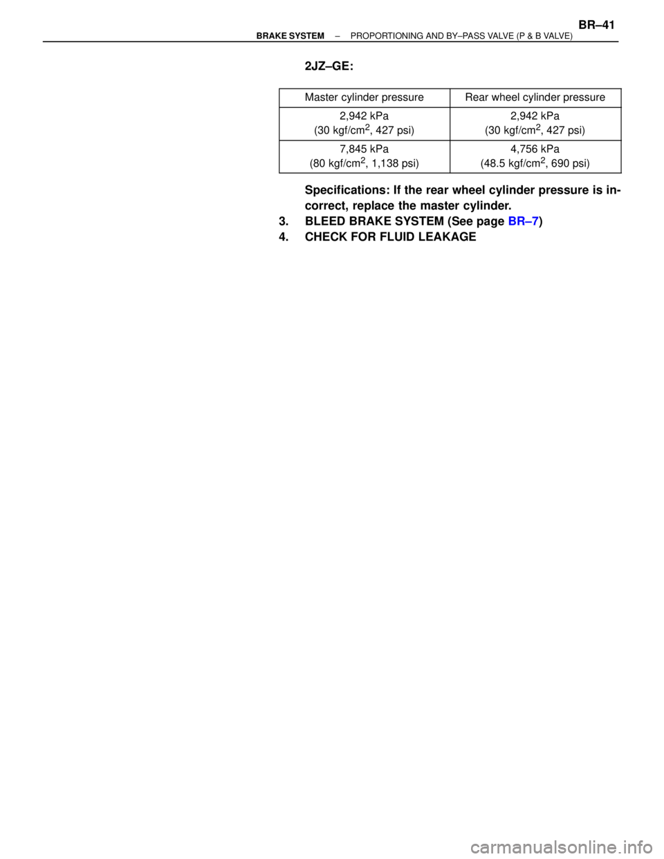
2JZ±GE:
����������� �����������Master cylinder pressure������������ ������������Rear wheel cylinder pressure
����������� �
���������� �����������
2,942 kPa
(30 kgf/cm2, 427 psi)
������������ �
����������� ������������
2,942 kPa
(30 kgf/cm2, 427 psi)
����������� �
���������� �����������
7,845 kPa
(80 kgf/cm2, 1,138 psi)
������������ �
����������� ������������
4,756 kPa
(48.5 kgf/cm2, 690 psi)
Specifications: If the rear wheel cylinder pressure is in-
correct, replace the master cylinder.
3. BLEED BRAKE SYSTEM (See page BR±7)
4. CHECK FOR FLUID LEAKAGE
± BRAKE SYSTEMPROPORTIONING AND BY±PASS VALVE (P & B VALVE)BR±41
Page 915 of 2543
 Start the engine, and run it at idle speed.
(b) Turn the selector switch of the actuator checker to the
ºFRONT RHº position.
(c) Push and hold in the MOTO")
4. INSPECT BRAKE ACTUATOR OPERATION
(a) Start the engine, and run it at idle speed.
(b) Turn the selector switch of the actuator checker to the
ºFRONT RHº position.
(c) Push and hold in the MOTOR switch for a few seconds.
(d) De p re ss th e bra ke pedal and hold it until step (g) is
completed.
(e) Push the POWER SWITCH, and check that the brake pedal
cannot be depressed.
NOTICE: Do not keep the MAIN switch pushed down for
more than 10 seconds.
(f) Re le a se th e switch , an d ch e ck th a t th e pedal can be
depressed.
(g) Push and hold in the MOTOR switch for a few seconds, and
check that the pedal returns.
(h) Release the brake pedal.
(i) Push and hold in the MOTOR switch for a few seconds.
(j) Depress the brake pedal and hold it for about 15 seconds. As
you hold the pedal down, push the MOTOR switch for a few
seconds. Check that the brake pedal does not pulsate.
5. INSPECT FOR OTHER WHEELS
(a) Turn the selector switch to the ºFRONT LHº position.
(b) Repeat (c) to (j) of step 4, checking the actuator operation in
the same way.
(c) Also, inspect the ºREAR RHº and ºREAR LHº positions
following the same procedure.
HINT: When inspecting the ºREAR LHº position, push the
REAR LH switch instead of the POWER SWITCH. This
makes it possible to inspect wherever the selector switch
position indicates. BR±46
± BRAKE SYSTEMANTI±LOCK BRAKE SYSTEM (ABS)
Page 925 of 2543

DIAGNOSTIC TROUBLE CODE CHART
If a malfunction code is displayed during the diagnostic trouble code check, check the circuit listed for that
code in the table below and proceed to the relevant page.
HINT: Using SST 09843±18020, connect the terminals Tc and E
1, and remove the short pin.
BR±65
BR±65
BR±71
BR±71
BR±77
BR±77
BR±80
BR±80
BR±83
BR±83
BR±83
BR±83
BR±86
BR±86
BR±88
BR±88
BR±88
BR±88
ON
ON
ON
ON
ON
ON
ON
ON
ON
ON
ON
ON
ON
ON
ON
ON
ON
ON
ON
ON
ON
ON
ON
ON
ON
ON
ON
ON
ON
ON
ON
ON
ON
ON
ON
ON
ON
ON
ON
OFF
OFF
OFF
OFF
OFF
OFF
OFF
OFF
OFF
OFF
OFF
OFF
OFF
OFF*
OFF*
CodeABS Warning Light
Blinking PatternIndicator
DiagnosisSee pageABS
Warning
LightTRAC
OFF
LightTRAC
Indicator
Light
Open or short in ABS solenoid relay circuit
B+ short in ABS solenoid relay circuit
Open or short in ABS motor relay circuit
B+ short in ABS motor relay circuit
Open or short in TRAC solenoid relay circuit
B+ short in TRAC solenoid relay circuit
Open or short in TRAC motor relay circuit
B+ short in TRAC motor relay circuit
Open or short in ABS actuator solenoid circuit
(SFR circuit)
Open or short in ABS actuator solenoid circuit
(SFL circuit)
Open or short in ABS actuator solenoid circuit
(SRR circuit)
Open or short in ABS actuator solenoid circuit
(SRL circuit)
Open or short in TRAC actuator solenoid circuit
(SMC circuit)
Open or short in TRAC actuator solenoid circuit
(SRC circuit)
Right front wheel speed sensor signal
malfunction
Left front wheel speed sensor signal
malfunction
Right rear wheel speed sensor signal
malfunction
Left rear wheel speed sensor signal
malfunction
BR±56± BRAKE SYSTEMANTI±LOCK BRAKE SYSTEM (ABS)
Page 926 of 2543

BR±88.
BR±88
BR±92
BR±95
BR±97
BR±98
BR±100
BR±102
BR±104
CodeABS Warning Light
Blinking Pattern
Indicator
DiagnosisSee pageABS
Warning
LightTRAC
Indicator
LightTRAC
OFF
Light
ON
ON
ON
ON
ON
ON
ON
ON
ON
ON
ON
ON
ON
ON
ON
ON
ON
ON
ON
ON
OFF
OFF
OFF
OFF
OFF
OFF*
OFF*
OFF*
OFF*
Always
ON
Open circuit in left front or right rear speed sensor
circuit
Open circuit in right front or left rear speed sensor
circuit
Low battery positive voltage or abnormally high
battery positive voltage
Open or short in lateral acceleration
sensor circuit
ABS pump motor is locked
Open in ABS pump motor ground
Brake fluid reservoir level low
Open circuit in TRAC pump motor circuit
TRAC ECU communication abnormal
Wheel speed sensor signal malfunction
Malfunction in ABS (& TRAC) ECU
�: Only vehicles with TRAC
*: When a malfunction causing code No. 17, 18, 55, 58, 61 or 62 is detected, the ABS warning light does
not light up, but the TRAC indicator light does. However, when checking the DTC, check the blinking
pattern of the ABS warning light.
± BRAKE SYSTEMANTI±LOCK BRAKE SYSTEM (ABS)BR±57
Page 928 of 2543
STD Voltage (V)Condition
Always
IG switch ON
IG switch ON, ABS warning light OFF
IG switch ON
IG switch ON, ABS warning light OFF
IG switch ON, ABS warning light OFF
IG switch O")
Symbols
(Terminals No.)STD Voltage (V)Condition
Always
IG switch ON
IG switch ON, ABS warning light OFF
IG switch ON
IG switch ON, ABS warning light OFF
IG switch ON, ABS warning light OFF
IG switch ON, ABS warning light OFF
IG switch ON, ABS warning light OFF
IG switch ON, ABS warning light OFF
IG switch ON, ABS warning light ON
IG switch ON, ABS warning light OFF
IG switch ON, PKB switch ON
IG switch ON, PKB switch OFF
Stop light switch OFF
Stop light switch ON
IG switch ON, ABS warning light OFF
IG switch ON
IG switch ON
IG switch ON
Slowly turn right front wheel
IG switch ON
IG switch ON
IG switch ON
IG switch ON, Vehicle parked on a level surface
IG switch ON, Vehicle parked on a level surface
Slowly turn left front wheel
Slowly turn left rear wheel
Slowly turn left rear wheel
10 ± 14
10 ± 14
9 ± 14
Below 1.0
10 ± 14
10 ± 14
10 ± 14
10 ± 14
10 ± 14
Below 2.0
10 ± 14
Below 1.5
10 ± 14
10 ± 14
10 ± 14
10 ± 14
10 ± 14
Below 1.5
AC generation
AC generation
AC generation
AC generation
4 ± 6
4 ± 6 or 7 ±11
BATGND
GND
GND
GND
GND
GND
GND
GND
GND
GND
GND
GND
GND
GND
GND
(A19±25)(A19±15)
(A19±12)(A19±2)
IG 1
SRR±
R±MR
(A19±11)(A19±24)
(A19±23)(A19±24)
(A19±1)(A19±2)
SFR
SFL
SRR
SRL
AST
WA
PKB
STP
D/G
Tc
Ts
FR +
FL +
RR +
RL +
GS 1
GS 2
(A19±13)
(A19±26)
(A19±14)
(A19±18)
(A18±13)
(A18±14)
(A18±6)
(A18±4)
(A19±5)
(A18±15)
(A19±16)
(A19±9)
(A18±8)
(A18±9)
(A18±12)
(A18±3)
(A19±2)
(A19±15)
(A19±15)
(A19±15)
(A19±15)
(A19±15)
(A19±2)
(A19±2)
(A19±2)
(A19±15)
(A19±3)
(A19±22)
(A18±16)
(A18±1)
(A19±15)
(A19±2)
FR±
FL±
RR±
RL±
ECU TERMINALS STANDARD VALUE
w/o TRAC:
± BRAKE SYSTEMANTI±LOCK BRAKE SYSTEM (ABS)BR±59
Page 930 of 2543
Symbols
(Terminals No.)STD Voltage (V)Conditions
IG switch ON
IG switch ON
IG switch ON
IG switch ON
IG switch ON
IG switch ON
IG switch ON
IG switch ON
IG switch ON
IG switch ON
Slowly turn right front wheel.
Slowly turn left front wheel.
Slowly turn right rear wheel.
Slowly turn left rear wheel.
Slowly turn right front wheel.
Slowly turn left front wheel.
Slowly turn right rear wheel.
Slowly turn left rear wheel.
IG switch ON, Vehicle parked on a level surface
IG switch ON, Vehicle parked on a level surface
IG switch ON
Pulse generation
Pulse generation
Pulse generation
Pulse generation
AC generation
AC generation
AC generation
TcGND
GNDTs
FR +FR ±
FL +FL ±
RR +RR ±
RL +RL ±
FROGND
FLOGND
RROGND
RLOGND
GS 1GND
GS 2GND
EXOGND
10 ±14
10 ±14
10 ±14
4 ±6
10 ±14
4 ± 6 or 7 ± 11
± BRAKE SYSTEMANTI±LOCK BRAKE SYSTEM (ABS)BR±61

FLUID PRESSURE INSPECTION
1. INSTALL LSPV GAUGE (SST) AND BLEED AIR
SST 09709±29017
2. RAISE MASTER CYLINDER PRESSURE AND CHECK
REAR WHEEL CYLINDER PR")
STD Voltage (V)Conditions
IG switch ON
IG switch ON
IG switch ON
IG switch ON
IG switch ON
IG switch ON
IG switch ON
IG switch ON
IG switch ON
IG switch ON
Slowly turn right fro")