Page 1357 of 2543

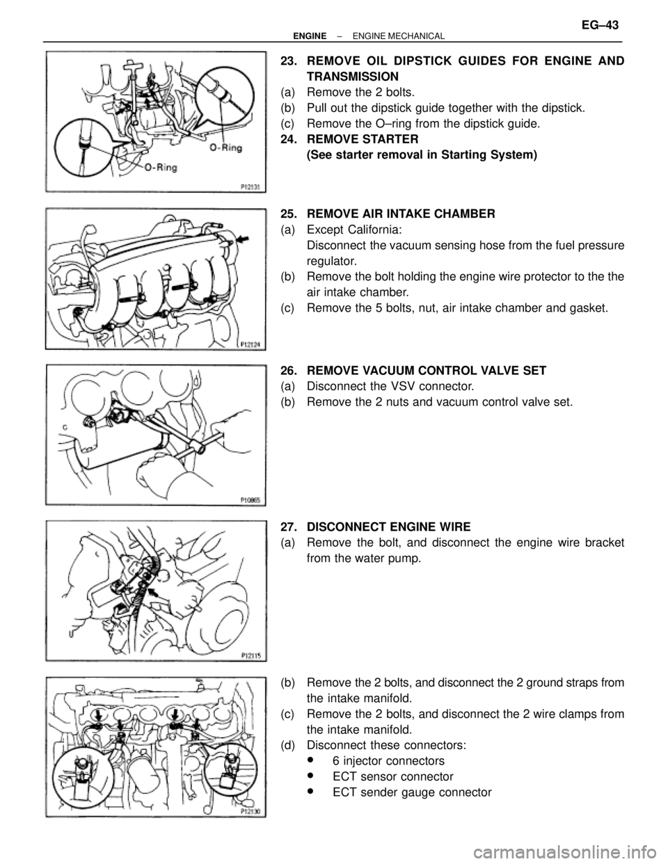
23. REMOVE OIL DIPSTICK GUIDES FOR ENGINE AND
TRANSMISSION
(a) Remove the 2 bolts.
(b) Pull out the dipstick guide together with the dipstick.
(c) Remove the O±ring from the dipstick guide.
24. REMOVE STARTER
(See starter removal in Starting System)
25. REMOVE AIR INTAKE CHAMBER
(a) Except California:
Disconnect the vacuum sensing hose from the fuel pressure
regulator.
(b) Remove the bolt holding the engine wire protector to the the
air intake chamber.
(c) Remove the 5 bolts, nut, air intake chamber and gasket.
26. REMOVE VACUUM CONTROL VALVE SET
(a) Disconnect the VSV connector.
(b) Remove the 2 nuts and vacuum control valve set.
27. DISCONNECT ENGINE WIRE
(a) Remove the bolt, and disconnect the engine wire bracket
from the water pump.
(b) Remove the 2 bolts, and disconnect the 2 ground straps from
the intake manifold.
(c) Remove the 2 bolts, and disconnect the 2 wire clamps from
the intake manifold.
(d) Disconnect these connectors:
w6 injector connectors
wECT sensor connector
wECT sender gauge connector
± ENGINEENGINE MECHANICALEG±43
Page 1358 of 2543
(e) Remove the 3 nuts, and disconnect the engine wire protector
from the intake manifold.
28. REMOVE WATER OUTLET AND NO.1 BYPASS HOSE
ASSEMBLY
Remove the 2 nuts, bolt and water outlet.
29. REMOVE INTAKE MANIFOLD STAY
Remove the 2 bolts and manifold stay.
30. REMOVE FUEL PRESSURE PULSATION DAMPER
(See step 2 in fuel pressure pulsation damper in SFI Sys-
tem)
31. REMOVE FUEL INLET PIPE
(a) Remove the clamp bolt from the intake manifold.
(b) Remove the union bolt and 2 gaskets, and disconnect the
fuel inlet pipe.
32. RE MO V E INTAKE MANIFO LD AND DE LIV E RY PIP E
ASSEMBLY
Remove the 6 bolts, 2 nuts, the intake manifold, delivery pipe
assembly and gasket. EG±44
± ENGINEENGINE MECHANICAL
Page 1359 of 2543
33. REMOVE NO.3, NO.1 AND NO.2 CYLINDER HEAD
COVERS
(a) Remove the PCV valve.
(b) Remove the 4 bolts, 4 nuts and No.3 cylinder head cover.
(c) Remove the 4 bolts, No.1 cylinder head cover and gasket.
(d) Remove the 4 bolts, No.2 cylinder head cover and gasket.
34. REMOVE CAMSHAFT TIMING PULLEYS
Hold the hexagon portion of the camshaft with a wrench, and
remove the pulley mounting bolt and camshaft pulley.
35. REMOVE NO.4 TIMING BELT COVER
Remove the 4 bolts and timing belt cover.
36. REMOVE CAMSHAFTS
(a) Uniformly loosen and remove the 4 No.1 bearing cap bolts.
(b) Using a screwdriver, pry out the 2 No.1 camshaft bearing
caps and oil seals.
NOTICE: Be careful not to damage the cap. Tape the screwdriv-
er tip.
± ENGINEENGINE MECHANICALEG±45
Page 1360 of 2543

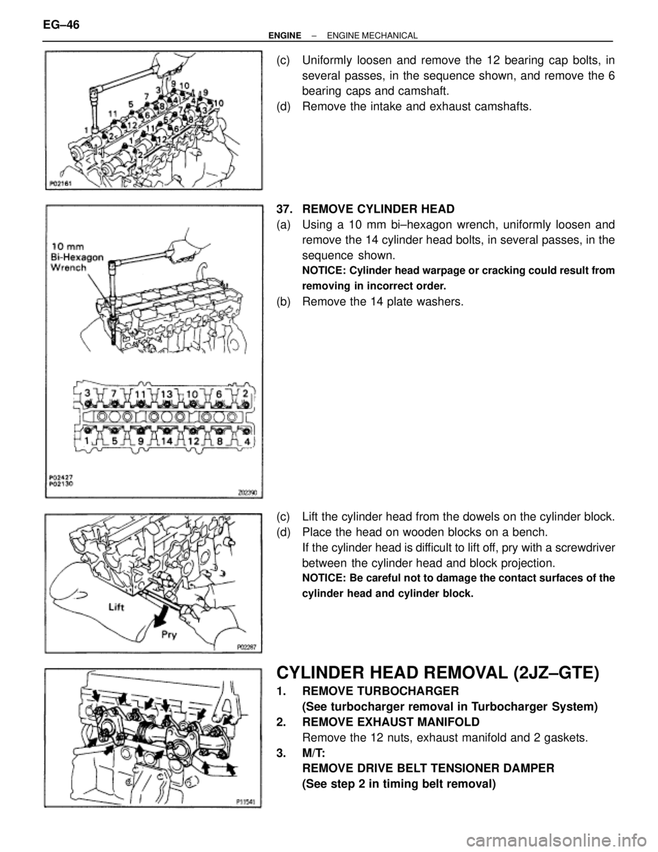
(c) Uniformly loosen and remove the 12 bearing cap bolts, in
several passes, in the sequence shown, and remove the 6
bearing caps and camshaft.
(d) Remove the intake and exhaust camshafts.
37. REMOVE CYLINDER HEAD
(a) Using a 10 mm bi±hexagon wrench, uniformly loosen and
remove the 14 cylinder head bolts, in several passes, in the
sequence shown.
NOTICE: Cylinder head warpage or cracking could result from
removing in incorrect order.
(b) Remove the 14 plate washers.
(c) Lift the cylinder head from the dowels on the cylinder block.
(d) Place the head on wooden blocks on a bench.
If the cylinder head is difficult to lift off, pry with a screwdriver
between the cylinder head and block projection.
NOTICE: Be careful not to damage the contact surfaces of the
cylinder head and cylinder block.
CYLINDER HEAD REMOVAL (2JZ±GTE)
1. REMOVE TURBOCHARGER
(See turbocharger removal in Turbocharger System)
2. REMOVE EXHAUST MANIFOLD
Remove the 12 nuts, exhaust manifold and 2 gaskets.
3. M/T:
REMOVE DRIVE BELT TENSIONER DAMPER
(See step 2 in timing belt removal) EG±46
± ENGINEENGINE MECHANICAL
Page 1361 of 2543
4. REMOVE DRIVE BELT
Loosen the drive belt tension by turning the drive belt tension-
er clockwise, and remove the drive belt.
5. REMOVE WATER OUTLET AND NO.1 WATER BYPASS
PIPE
(a) Disconnect the upper radiator hose from the water outlet.
(b) Disconnect the ECT sensor and sender gauge connectors.
(c) Remove the 2 bolts, water outlet and gasket.
(d) Remove the No.1 water bypass pipe and 2 O±rings.
6. DISCONNECT PS PUMP WITHOUT DISCONNECTING
HOSES
(a) Disconnect these hoses:
(1) Air hose from throttle body
(2) Air hose from air intake chamber
(b) Remove the 2 bolts, and disconnect the pump housing from
the pump bracket.
HINT: Put aside the pump housing, and suspend it securely.
7. DISCONNECT FUEL RETURN HOSE
Disconnect the fuel return hose from the fuel return pipe. Plug
the hose end.
8. REMOVE AIR INTAKE CHAMBER ASSEMBLY
(See injector removal in SFI System)
± ENGINEENGINE MECHANICALEG±47
Page 1362 of 2543

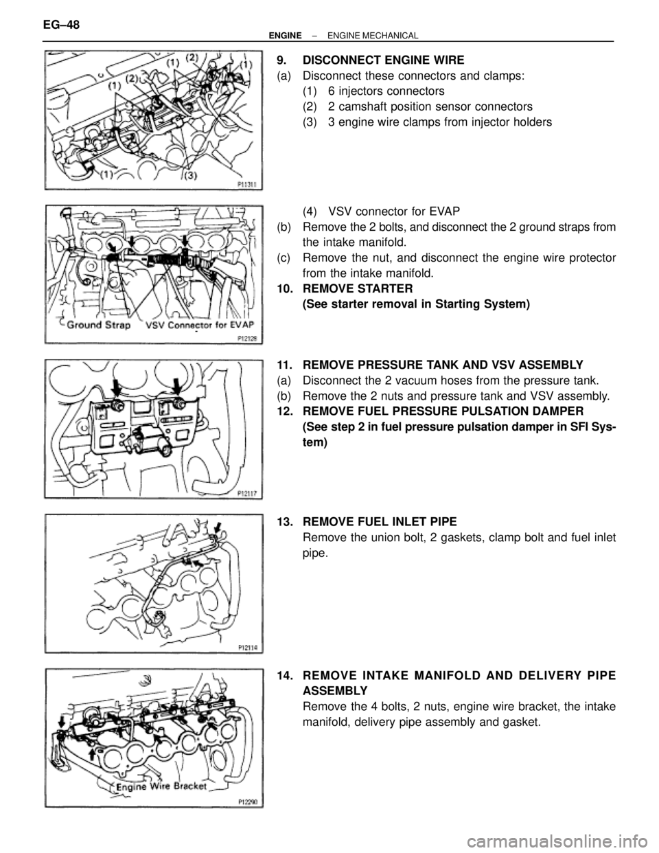
9. DISCONNECT ENGINE WIRE
(a) Disconnect these connectors and clamps:
(1) 6 injectors connectors
(2) 2 camshaft position sensor connectors
(3) 3 engine wire clamps from injector holders
(4) VSV connector for EVAP
(b) Remove the 2 bolts, and disconnect the 2 ground straps from
the intake manifold.
(c) Remove the nut, and disconnect the engine wire protector
from the intake manifold.
10. REMOVE STARTER
(See starter removal in Starting System)
11. REMOVE PRESSURE TANK AND VSV ASSEMBLY
(a) Disconnect the 2 vacuum hoses from the pressure tank.
(b) Remove the 2 nuts and pressure tank and VSV assembly.
12. REMOVE FUEL PRESSURE PULSATION DAMPER
(See step 2 in fuel pressure pulsation damper in SFI Sys-
tem)
13. REMOVE FUEL INLET PIPE
Remove the union bolt, 2 gaskets, clamp bolt and fuel inlet
pipe.
14. RE MO V E INTAKE MANIFO LD AND DE LIV E RY PIP E
ASSEMBLY
Remove the 4 bolts, 2 nuts, engine wire bracket, the intake
manifold, delivery pipe assembly and gasket. EG±48
± ENGINEENGINE MECHANICAL
Page 1363 of 2543

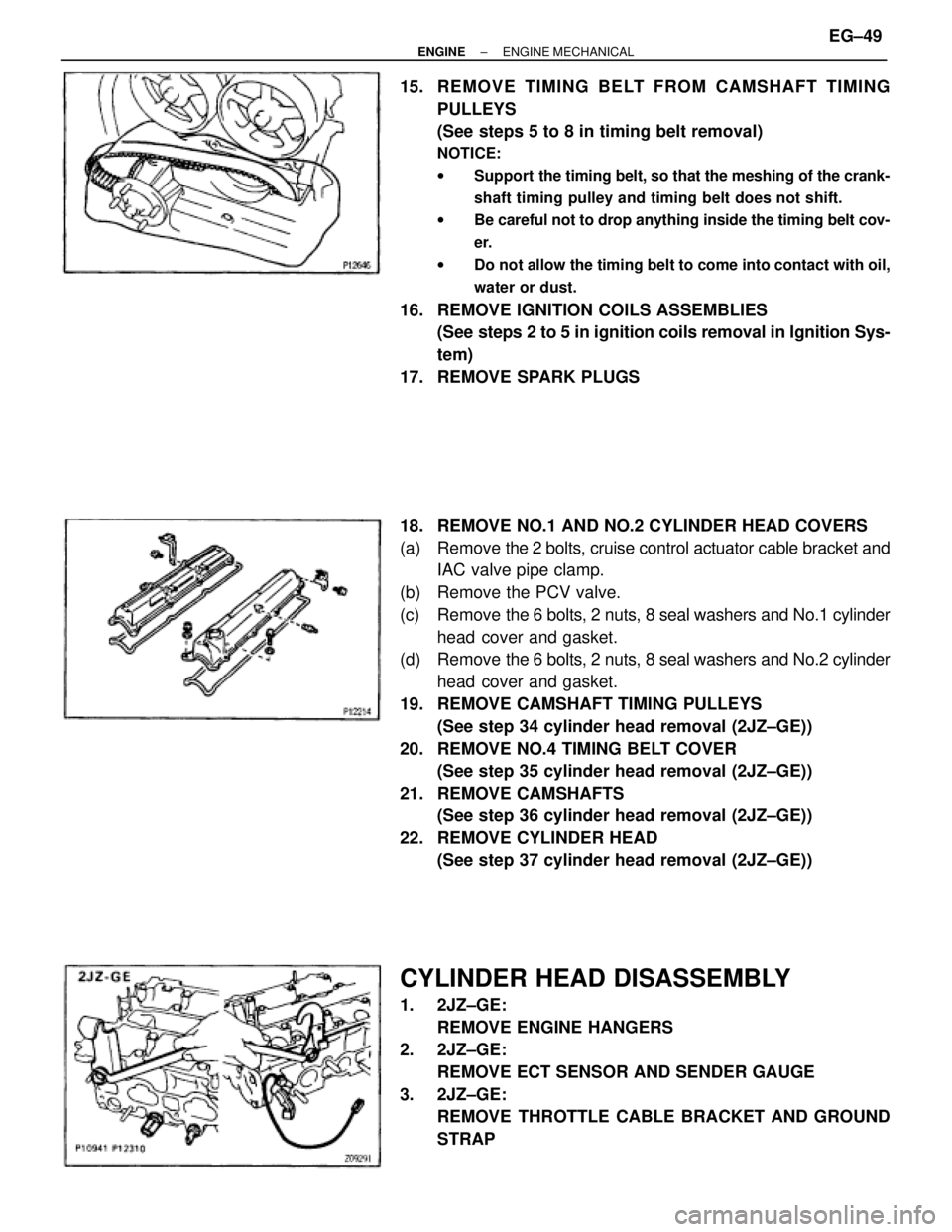
15. REMOVE TIMING BELT FROM CAMSHAFT TIMING
PULLEYS
(See steps 5 to 8 in timing belt removal)
NOTICE:
wSupport the timing belt, so that the meshing of the crank-
shaft timing pulley and timing belt does not shift.
wBe careful not to drop anything inside the timing belt cov-
er.
wDo not allow the timing belt to come into contact with oil,
water or dust.
16. REMOVE IGNITION COILS ASSEMBLIES
(See steps 2 to 5 in ignition coils removal in Ignition Sys-
tem)
17. REMOVE SPARK PLUGS
18. REMOVE NO.1 AND NO.2 CYLINDER HEAD COVERS
(a) Remove the 2 bolts, cruise control actuator cable bracket and
IAC valve pipe clamp.
(b) Remove the PCV valve.
(c) Remove the 6 bolts, 2 nuts, 8 seal washers and No.1 cylinder
head cover and gasket.
(d) Remove the 6 bolts, 2 nuts, 8 seal washers and No.2 cylinder
head cover and gasket.
19. REMOVE CAMSHAFT TIMING PULLEYS
(See step 34 cylinder head removal (2JZ±GE))
20. REMOVE NO.4 TIMING BELT COVER
(See step 35 cylinder head removal (2JZ±GE))
21. REMOVE CAMSHAFTS
(See step 36 cylinder head removal (2JZ±GE))
22. REMOVE CYLINDER HEAD
(See step 37 cylinder head removal (2JZ±GE))
CYLINDER HEAD DISASSEMBLY
1. 2JZ±GE:
REMOVE ENGINE HANGERS
2. 2JZ±GE:
REMOVE ECT SENSOR AND SENDER GAUGE
3. 2JZ±GE:
REMOVE THROTTLE CABLE BRACKET AND GROUND
STRAP
± ENGINEENGINE MECHANICALEG±49
Page 1364 of 2543
4. 2JZ±GTE:
REMOVE ENGINE HANGERS AND GROUND STRAP
5. 2JZ±GTE:
REMOVE CAMSHAFT POSITION SENSORS
6. REMOVE EGR COOLER
7. REMOVE VALVE LIFTERS AND SHIMS
HINT: Store the valve lifters and shims in correct order.
8. REMOVE VALVES
(a) Using SST, compress the valve spring and remove the 2
keepers.
SST 09202±70010
(b) Remove the spring retainer, valve spring, valve and spring
seat.
HINT: Store the valves, valve springs, spring seats and spring
retainers in correct order.
(c) Using needle±nose pliers, remove the oil seal.
CYLINDER HEAD COMPONENTS
INSPECTION AND REPAIR
1. CLEAN TOP SURFACES OF PISTONS AND CYLINDER
BLOCK
(a) Turn the crankshaft, and bring each piston to top dead center
(TDC). Using a gasket scraper, remove all the carbon from
the piston top surface. EG±50
± ENGINEENGINE MECHANICAL