Page 1349 of 2543
± ENGINEENGINE MECHANICALEG±35
Page 1350 of 2543
EG±36± ENGINEENGINE MECHANICAL
Page 1351 of 2543
± ENGINEENGINE MECHANICALEG±37
Page 1352 of 2543
EG±38± ENGINEENGINE MECHANICAL
Page 1353 of 2543
± ENGINEENGINE MECHANICALEG±39
Page 1354 of 2543
EG±40± ENGINEENGINE MECHANICAL
Page 1355 of 2543

CYLINDER HEAD REMOVAL (2JZ±GE)
1. REMOVE ENGINE UNDER COVER
2. DRAIN ENGINE COOLANT
3. REMOVE AIR CLEANER DUCT
4. REMOVE AIR CLEANER, VAF METER AND INTAKE AIR
CONNECTOR PIPE ASSEMBLY
(See step 6 in engine removal in Engine Mechanical)
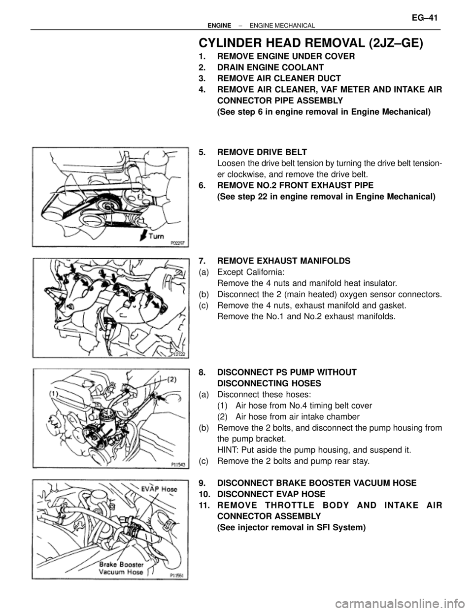
5. REMOVE DRIVE BELT
Loosen the drive belt tension by turning the drive belt tension-
er clockwise, and remove the drive belt.
6. REMOVE NO.2 FRONT EXHAUST PIPE
(See step 22 in engine removal in Engine Mechanical)
7. REMOVE EXHAUST MANIFOLDS
(a) Except California:
Remove the 4 nuts and manifold heat insulator.
(b) Disconnect the 2 (main heated) oxygen sensor connectors.
(c) Remove the 4 nuts, exhaust manifold and gasket.
Remove the No.1 and No.2 exhaust manifolds.
8. DISCONNECT PS PUMP WITHOUT
DISCONNECTING HOSES
(a) Disconnect these hoses:
(1) Air hose from No.4 timing belt cover
(2) Air hose from air intake chamber
(b) Remove the 2 bolts, and disconnect the pump housing from
the pump bracket.
HINT: Put aside the pump housing, and suspend it.
(c) Remove the 2 bolts and pump rear stay.
9. DISCONNECT BRAKE BOOSTER VACUUM HOSE
10. DISCONNECT EVAP HOSE
11. REMOVE THROTTLE BODY AND INTAKE AIR
CONNECTOR ASSEMBLY
(See injector removal in SFI System)
± ENGINEENGINE MECHANICALEG±41
Page 1356 of 2543

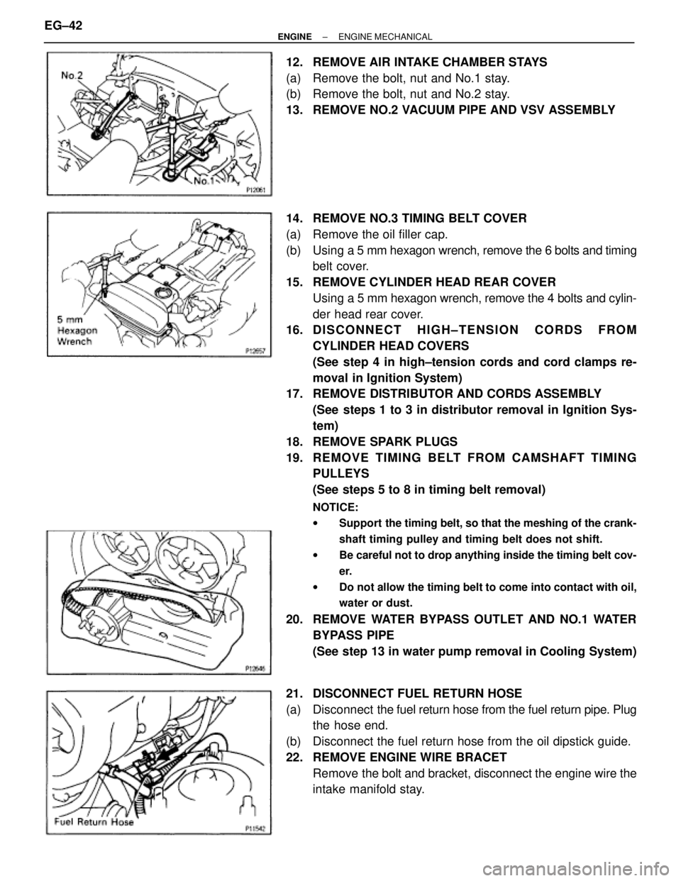
12. REMOVE AIR INTAKE CHAMBER STAYS
(a) Remove the bolt, nut and No.1 stay.
(b) Remove the bolt, nut and No.2 stay.
13. REMOVE NO.2 VACUUM PIPE AND VSV ASSEMBLY
14. REMOVE NO.3 TIMING BELT COVER
(a) Remove the oil filler cap.
(b) Using a 5 mm hexagon wrench, remove the 6 bolts and timing
belt cover.
15. REMOVE CYLINDER HEAD REAR COVER
Using a 5 mm hexagon wrench, remove the 4 bolts and cylin-
der head rear cover.
16. D I S C O N N E C T H I G H ± T E N S I O N C O R D S F R O M
CYLINDER HEAD COVERS
(See step 4 in high±tension cords and cord clamps re-
moval in Ignition System)
17. REMOVE DISTRIBUTOR AND CORDS ASSEMBLY
(See steps 1 to 3 in distributor removal in Ignition Sys-
tem)
18. REMOVE SPARK PLUGS
19. RE MO V E TIMING BE LT FRO M CAMS HAFT TIMING
PULLEYS
(See steps 5 to 8 in timing belt removal)
NOTICE:
wSupport the timing belt, so that the meshing of the crank-
shaft timing pulley and timing belt does not shift.
wBe careful not to drop anything inside the timing belt cov-
er.
wDo not allow the timing belt to come into contact with oil,
water or dust.
20. REMOVE WATER BYPASS OUTLET AND NO.1 WATER
BYPASS PIPE
(See step 13 in water pump removal in Cooling System)
21. DISCONNECT FUEL RETURN HOSE
(a) Disconnect the fuel return hose from the fuel return pipe. Plug
the hose end.
(b) Disconnect the fuel return hose from the oil dipstick guide.
22. REMOVE ENGINE WIRE BRACET
Remove the bolt and bracket, disconnect the engine wire the
intake manifold stay. EG±42
± ENGINEENGINE MECHANICAL