Page 530 of 2543
TIME LAG TEST
When the shift lever is shifted while the engine is idling, there will be a certain time lapse or lag before the
shock can be felt. This is used for checking the condition of the O/D direct clutch, forward clutch, direct
clutch, and first and reverse brake.
NOTICE:
wDo the test at normal operating fluid temp. 50±805C (122±1765F).
wBe sure to allow 1 minute interval between tests.
wTake 3 measurements and take the average value.
MEASURE TIME LAG
(a) Fully apply the parking brake
(b) Start the engine and check idle speed.
Idle speed:
650+50 rpm (In N position and air conditioner OFF)
(c) Shift the shift lever from N to D position. Using a stop watch, measure the time it takes from shifting the
lever until the shock is felt.
In same manner, measure the time lag for N " R.
Time lag:
N
"D Less than 1.2 seconds
N
"R Less than 1.5 seconds
AT2±46± A340E (2JZÐGTE) AUTOMATIC TRANSMISSIONTROUBLESHOOTING
Page 532 of 2543
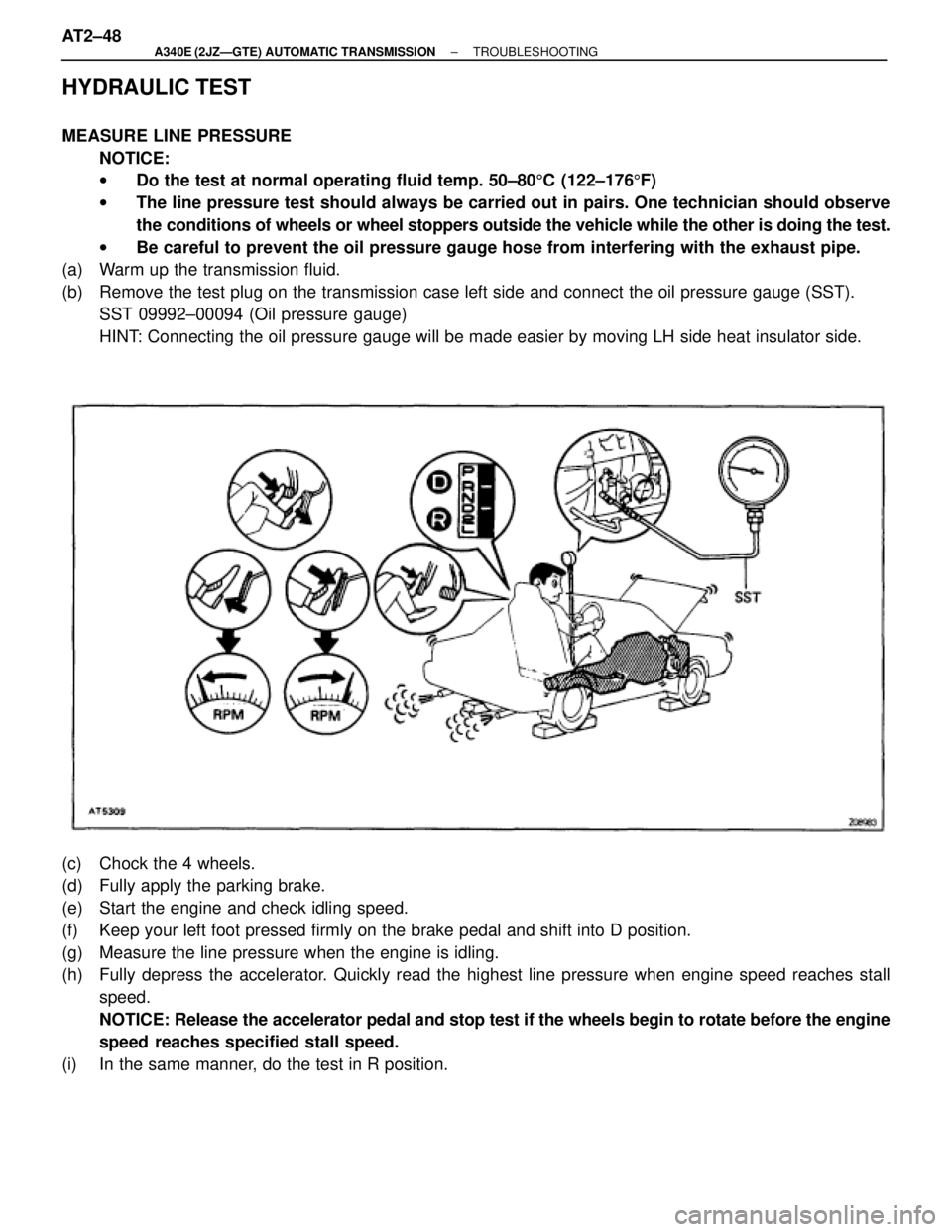
HYDRAULIC TEST
MEASURE LINE PRESSURE
NOTICE:
wDo the test at normal operating fluid temp. 50±805C (122±1765F)
wThe line pressure test should always be carried out in pairs. One technician should observe
the conditions of wheels or wheel stoppers outside the vehicle while the other is doing the test.
wBe careful to prevent the oil pressure gauge hose from interfering with the exhaust pipe.
(a) Warm up the transmission fluid.
(b) Remove the test plug on the transmission case left side and connect the oil pressure gauge (SST).
SST 09992±00094 (Oil pressure gauge)
HINT: Connecting the oil pressure gauge will be made easier by moving LH side heat insulator side.
(c) Chock the 4 wheels.
(d) Fully apply the parking brake.
(e) Start the engine and check idling speed.
(f) Keep your left foot pressed firmly on the brake pedal and shift into D position.
(g) Measure the line pressure when the engine is idling.
(h) Fully depress the accelerator. Quickly read the highest line pressure when engine speed reaches stall
speed.
NOTICE: Release the accelerator pedal and stop test if the wheels begin to rotate before the engine
speed reaches specified stall speed.
(i) In the same manner, do the test in R position. AT2±48
± A340E (2JZÐGTE) AUTOMATIC TRANSMISSIONTROUBLESHOOTING
Page 533 of 2543
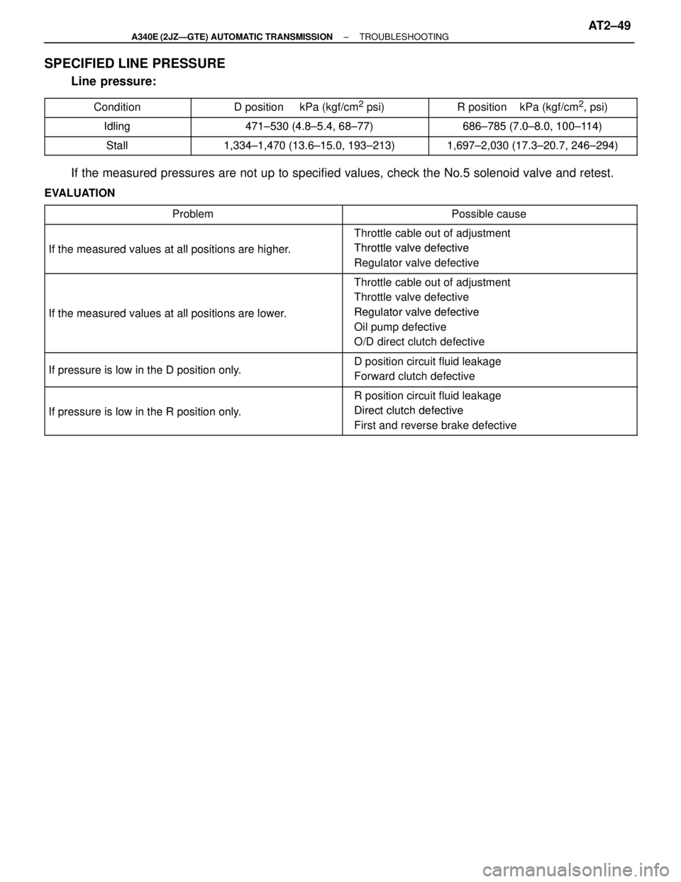
SPECIFIED LINE PRESSURE
Line pressure:
���������� ����������Condition��������������� ���������������D position kPa (kgf/cm2 psi)������������� �������������R position kPa (kgf/cm2, psi)���������� ����������Idling471±530 (4 8±5 4 68±77)686±785 (7 0±8 0 100±114)����������Idling471±530 (4.8±5.4, 68±77)686±785 (7.0±8.0, 100±114)���������� ����������
Stall1 334±1 470 (13 6±15 0 193±213)1 697±2 030 (17 3±20 7 246±294)���������� ����������Stall1,334±1,470 (13.6±15.0, 193±213)1,697±2,030 (17.3±20.7, 246±294)
If the measured pressures are not up to specified values, check the No.5 solenoid valve and retest.
EVALUATION������������������ �
�����������������
������������������
Problem
������������������ �
����������������� ������������������Possible cause
������������������ ������������������
If the measured values at allpositions are higher
� Throttle cable out of adjustment
�Throttle valve defective������������������ ������������������If the measured values at all positions are higher.� Throttle valve defective
� Regulator valve defective
������������������ �
�����������������
������������������
������������������If the measured values at allpositions are lower
� Throttle cable out of adjustment
� Throttle valve defective
�Regulator valve defective������������������ �
�����������������
������������������
If the measured values at all positions are lower.� Regulator valve defective
� Oil pump defective
� O/D direct clutch defective
������������������ ������������������
Ifpressure is low in the Dposition only� D position circuit fluid leakage
������������������ ������������������If pressure is low in the D position only.g
� Forward clutch defective
������������������ �
�����������������
������������������
Ifpressure is low in the Rposition only
� R position circuit fluid leakage
�Direct clutch defective
������������������ ������������������
If pressure is low in the R position only.� Direct clutch defective
� First and reverse brake defective
± A340E (2JZÐGTE) AUTOMATIC TRANSMISSIONTROUBLESHOOTINGAT2±49
Page 534 of 2543
MEASURE ACCUMULATOR BACK PRESSURE
NOTICE:
wDo the test at normal operating fluid temp. 50±805C (122±1765F).
wBe careful to prevent the oil pressure gauge hose from interfering with the exhaust pipe.
(a) Warm up the transmission fluid.
(b) Remove the test plug on the transmission case rear right side and connect the oil pressure gauge
(SST)
SST 09992±00094 (Oil pressure gauge)
HINT: Connecting the oil pressure gauge will be made easier by moving the RH side head insulator aside.
(c) Remove the passenger side floor carpet and ECM protector.
(d) Connect the SST (check harness A) between ECM and connector of vehicle wire harness.
SST: 09990±01000
(e) Install one test lead probe into the terminal SLN of the ECM wire harness side connector and take care
not to ground the other test lead probe.
HINT: Prepare test leads which are connected with an approximately 8 W light bulb. AT2±50
± A340E (2JZÐGTE) AUTOMATIC TRANSMISSIONTROUBLESHOOTING
Page 538 of 2543
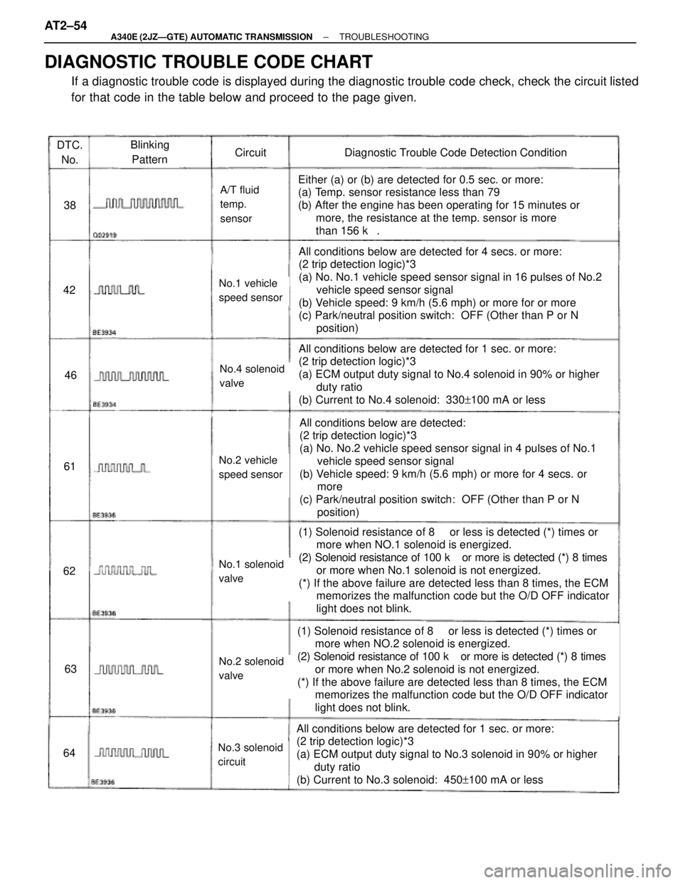
DTC.
No.Blinking
PatternCircuitDiagnostic Trouble Code Detection Condition
38
42
46
61
62
63
64
A/T fluid
temp.
sensor
No.1 vehicle
speed sensor
No.4 solenoid
valve
No.2 vehicle
speed sensor
No.1 solenoid
valve
No.2 solenoid
valve
No.3 solenoid
circuit
Either (a) or (b) are detected for 0.5 sec. or more:
(a) Temp. sensor resistance less than 79 �
(b) After the engine has been operating for 15 minutes or
more, the resistance at the temp. sensor is more
than 156 k��
All conditions below are detected for 4 secs. or more:
(2 trip detection logic)*3
(a) No. No.1 vehicle speed sensor signal in 16 pulses of No.2
vehicle speed sensor signal
(b) Vehicle speed: 9 km/h (5.6 mph) or more for or more
(c) Park/neutral position switch: OFF (Other than P or N
position)
All conditions below are detected for 1 sec. or more:
(2 trip detection logic)*3
(a) ECM output duty signal to No.4 solenoid in 90% or higher
duty ratio
(b) Current to No.4 solenoid: 330+100 mA or less
All conditions below are detected:
(2 trip detection logic)*3
(a) No. No.2 vehicle speed sensor signal in 4 pulses of No.1
vehicle speed sensor signal
(b) Vehicle speed: 9 km/h (5.6 mph) or more for 4 secs. or
more
(c) Park/neutral position switch: OFF (Other than P or N
position)
(1) Solenoid resistance of 8 ��or less is detected (*) times or
more when NO.1 solenoid is energized.
(2) Solenoid resistance of 100 k� or more is detected (*) 8 times
or more when No.1 solenoid is not energized.
(*) If the above failure are detected less than 8 times, the ECM
memorizes the malfunction code but the O/D OFF indicator
light does not blink.
(1) Solenoid resistance of 8 ��or less is detected (*) times or
more when NO.2 solenoid is energized.
(2) Solenoid resistance of 100 k� or more is detected (*) 8 times
or more when No.2 solenoid is not energized.
(*) If the above failure are detected less than 8 times, the ECM
memorizes the malfunction code but the O/D OFF indicator
light does not blink.
All conditions below are detected for 1 sec. or more:
(2 trip detection logic)*3
(a) ECM output duty signal to No.3 solenoid in 90% or higher
duty ratio
(b) Current to No.3 solenoid: 450+100 mA or less
DIAGNOSTIC TROUBLE CODE CHART
If a diagnostic trouble code is displayed during the diagnostic trouble code check, check the circuit listed
for that code in the table below and proceed to the page given. AT2±54
± A340E (2JZÐGTE) AUTOMATIC TRANSMISSIONTROUBLESHOOTING
Page 555 of 2543
INSPECTION PROCEDURE
Check A/T fluid temp. sensor.
Check harness and connector between A/T fluid temp. sensor and ECM
(See page IN±30).
Replace A/T fluid temp. sensor.
Repair or replace harness or connector.
Check sensor resistance
Remove A/T fluid temp. sensor.
Measure resistance between terminals of A/T fluid
temp. sensor at 20°C (68°F) and 110°C (230°F).
Resistance:
20°C (68°F): Approx. 12.08 k�
11 0°C (230°F): Approx. 0.78 k�
20°C (68°F) and 110°C (230°F).
Check and replace ECM.
± A340E (2JZÐGTE) AUTOMATIC TRANSMISSIONTROUBLESHOOTINGAT2±71
Page 590 of 2543
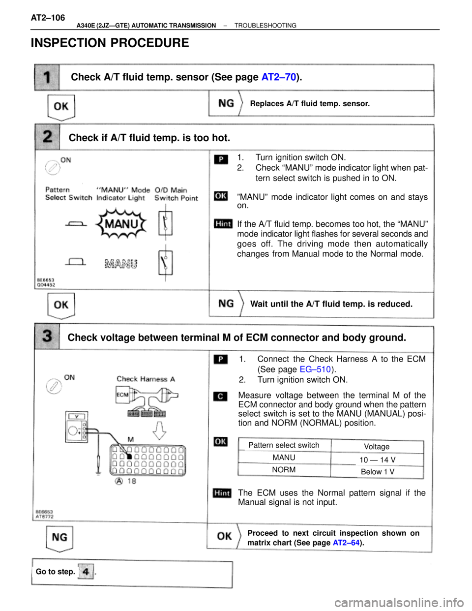
Check if A/T fluid temp. is too hot.
1. Turn ignition switch ON.
2. Check ªMANUº mode indicator light when pat-
tern select switch is pushed in to ON.
ºMANUº mode indicator light comes on and stays
on.
If the A/T fluid temp. becomes too hot, the ªMANUº
mode indicator light flashes for several seconds and
goes off. The driving mode then automatically
changes from Manual mode to the Normal mode.
Measure voltage between the terminal M of the
ECM connector and body ground when the pattern
select switch is set to the MANU (MANUAL) posi-
tion and NORM (NORMAL) position.
Check A/T fluid temp. sensor (See page AT2±70).
Check voltage between terminal M of ECM connector and body ground.
Replaces A/T fluid temp. sensor.
1. Connect the Check Harness A to the ECM
(See page EG±510).
2. Turn ignition switch ON.
Proceed to next circuit inspection shown on
matrix chart (See page AT2±64).
The ECM uses the Normal pattern signal if the
Manual signal is not input.
Pattern select switchVoltage
MANU
NORM
10 Ð 14 V
Below 1 V
Go to step.
Wait until the A/T fluid temp. is reduced.
INSPECTION PROCEDURE
AT2±106± A340E (2JZÐGTE) AUTOMATIC TRANSMISSIONTROUBLESHOOTING
Page 1246 of 2543
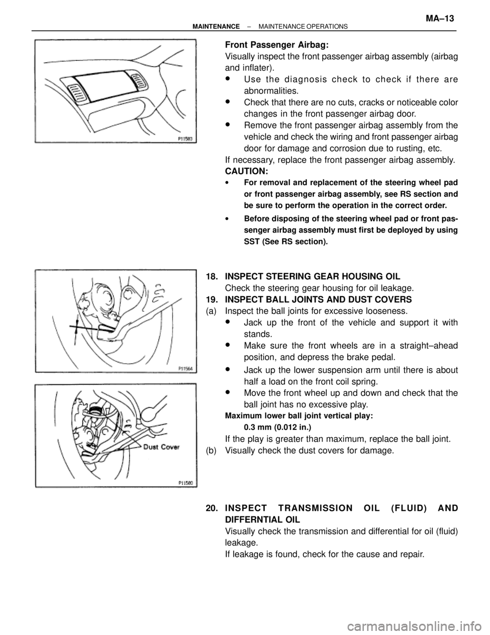
Front Passenger Airbag:
Visually inspect the front passenger airbag assembly (airbag
and inflater).
wUse the diagnosis check to check if there are
abnormalities.
wCheck that there are no cuts, cracks or noticeable color
changes in the front passenger airbag door.
wRemove the front passenger airbag assembly from the
vehicle and check the wiring and front passenger airbag
door for damage and corrosion due to rusting, etc.
If necessary, replace the front passenger airbag assembly.
CAUTION:
wFor removal and replacement of the steering wheel pad
or front passenger airbag assembly, see RS section and
be sure to perform the operation in the correct order.
wBefore disposing of the steering wheel pad or front pas-
senger airbag assembly must first be deployed by using
SST (See RS section).
18. INSPECT STEERING GEAR HOUSING OIL
Check the steering gear housing for oil leakage.
19. INSPECT BALL JOINTS AND DUST COVERS
(a) Inspect the ball joints for excessive looseness.
wJack up the front of the vehicle and support it with
stands.
wMake sure the front wheels are in a straight±ahead
position, and depress the brake pedal.
wJack up the lower suspension arm until there is about
half a load on the front coil spring.
wMove the front wheel up and down and check that the
ball joint has no excessive play.
Maximum lower ball joint vertical play:
0.3 mm (0.012 in.)
If the play is greater than maximum, replace the ball joint.
(b) Visually check the dust covers for damage.
20. I NSPECT TRANSMISSION OIL (FLUID) AND
DIFFERNTIAL OIL
Visually check the transmission and differential for oil (fluid)
leakage.
If leakage is found, check for the cause and repair.
± MAINTENANCEMAINTENANCE OPERATIONSMA±13