Page 428 of 2543
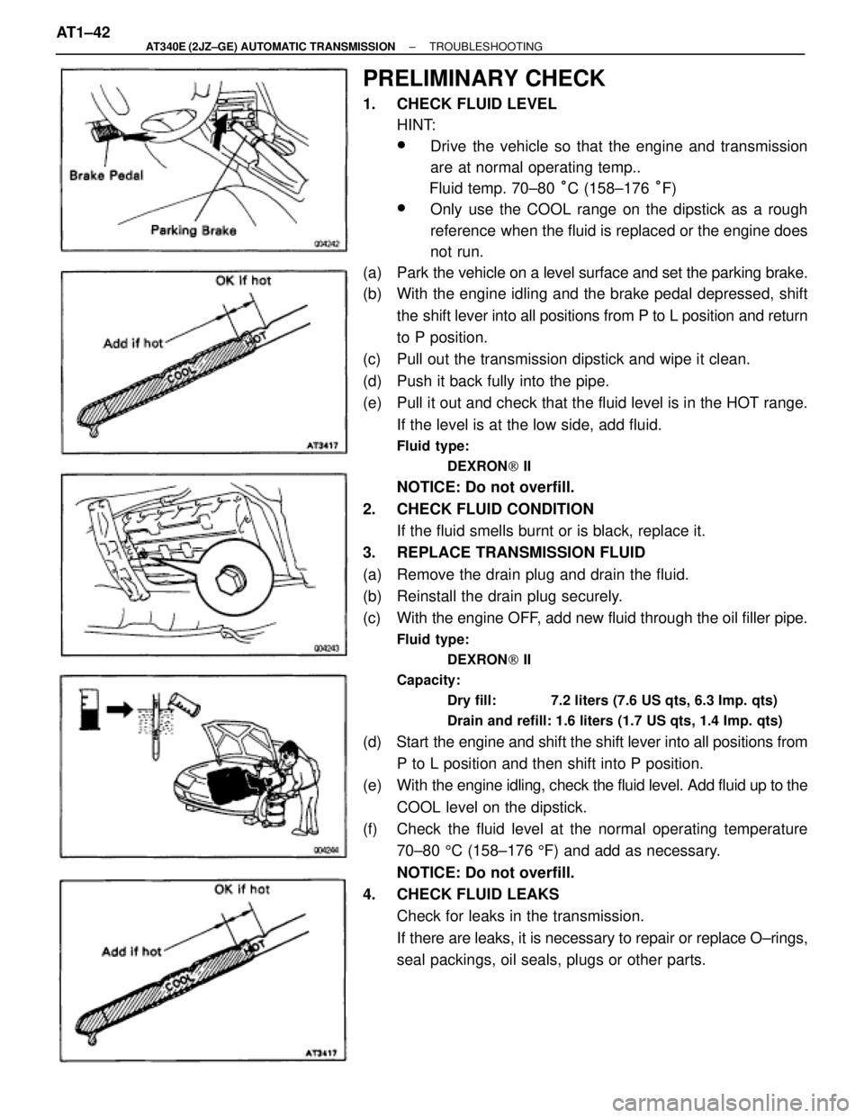
PRELIMINARY CHECK
1. CHECK FLUID LEVEL
HINT:
wDrive the vehicle so that the engine and transmission
are at normal operating temp..
Fluid temp. 70±80 °C (158±176 °F)
wOnly use the COOL range on the dipstick as a rough
reference when the fluid is replaced or the engine does
not run.
(a) Park the vehicle on a level surface and set the parking brake.
(b) With the engine idling and the brake pedal depressed, shift
the shift lever into all positions from P to L position and return
to P position.
(c) Pull out the transmission dipstick and wipe it clean.
(d) Push it back fully into the pipe.
(e) Pull it out and check that the fluid level is in the HOT range.
If the level is at the low side, add fluid.
Fluid type:
DEXRON[ II
NOTICE: Do not overfill.
2. CHECK FLUID CONDITION
If the fluid smells burnt or is black, replace it.
3. REPLACE TRANSMISSION FLUID
(a) Remove the drain plug and drain the fluid.
(b) Reinstall the drain plug securely.
(c) With the engine OFF, add new fluid through the oil filler pipe.
Fluid type:
DEXRON[ II
Capacity:
Dry fill: 7.2 liters (7.6 US qts, 6.3 Imp. qts)
Drain and refill: 1.6 liters (1.7 US qts, 1.4 Imp. qts)
(d) Start the engine and shift the shift lever into all positions from
P to L position and then shift into P position.
(e) With the engine idling, check the fluid level. Add fluid up to the
COOL level on the dipstick.
(f) Check the fluid level at the normal operating temperature
70±80 5C (158±176 5F) and add as necessary.
NOTICE: Do not overfill.
4. CHECK FLUID LEAKS
Check for leaks in the transmission.
If there are leaks, it is necessary to repair or replace O±rings,
seal packings, oil seals, plugs or other parts. AT1±42
± AT340E (2JZ±GE) AUTOMATIC TRANSMISSIONTROUBLESHOOTING
Page 430 of 2543
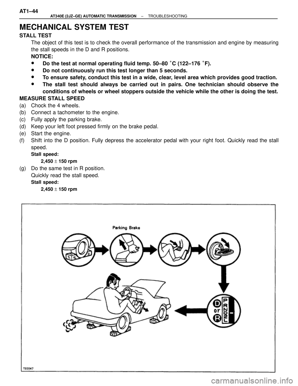
MECHANICAL SYSTEM TEST
STALL TEST
The object of this test is to check the overall performance of the transmission and engine by measuring
the stall speeds in the D and R positions.
NOTICE:
wDo the test at normal operating fluid temp. 50±80 °C (122±176 °F).
wDo not continuously run this test longer than 5 seconds.
wTo ensure safety, conduct this test in a wide, clear, level area which provides good traction.
wThe stall test should always be carried out in pairs. One technician should observe the
conditions of wheels or wheel stoppers outside the vehicle while the other is doing the test.
MEASURE STALL SPEED
(a) Chock the 4 wheels.
(b) Connect a tachometer to the engine.
(c) Fully apply the parking brake.
(d) Keep your left foot pressed firmly on the brake pedal.
(e) Start the engine.
(f) Shift into the D position. Fully depress the accelerator pedal with your right foot. Quickly read the stall
speed.
Stall speed:
2,450 + 150 rpm
(g) Do the same test in R position.
Quickly read the stall speed.
Stall speed:
2,450 + 150 rpm
AT1±44± AT340E (2JZ±GE) AUTOMATIC TRANSMISSIONTROUBLESHOOTING
Page 432 of 2543
TIME LAG TEST
When the shift lever is shifted while the engine is idling, there will be a certain time lapse or lag before the
shock can be felt. This is used for checking the condition of the O/D direct clutch, forward clutch, direct
clutch, and first and reverse brake.
NOTICE:
wDo the test at normal operating fluid temp. 50±80
°C (122±176 °F).
wBe sure to allow a one minute interval between tests.
wTake 3 measurements and take the average value.
MEASURE TIME LAG
(a) Fully apply the parking brake
(b) Start the engine and check idle speed.
Idle speed:
700 + 50 rpm (In N position and air conditioner OFF)
(c) Shift the shift lever from N to D position. Using a stop watch, measure the time it takes from shifting the
lever until the shock is felt.
In same manner, measure the time lag for N " R.
Time lag:
N
" D Less than 1.2 seconds
N
" R Less than 1.5 seconds
AT1±46± AT340E (2JZ±GE) AUTOMATIC TRANSMISSIONTROUBLESHOOTING
Page 434 of 2543
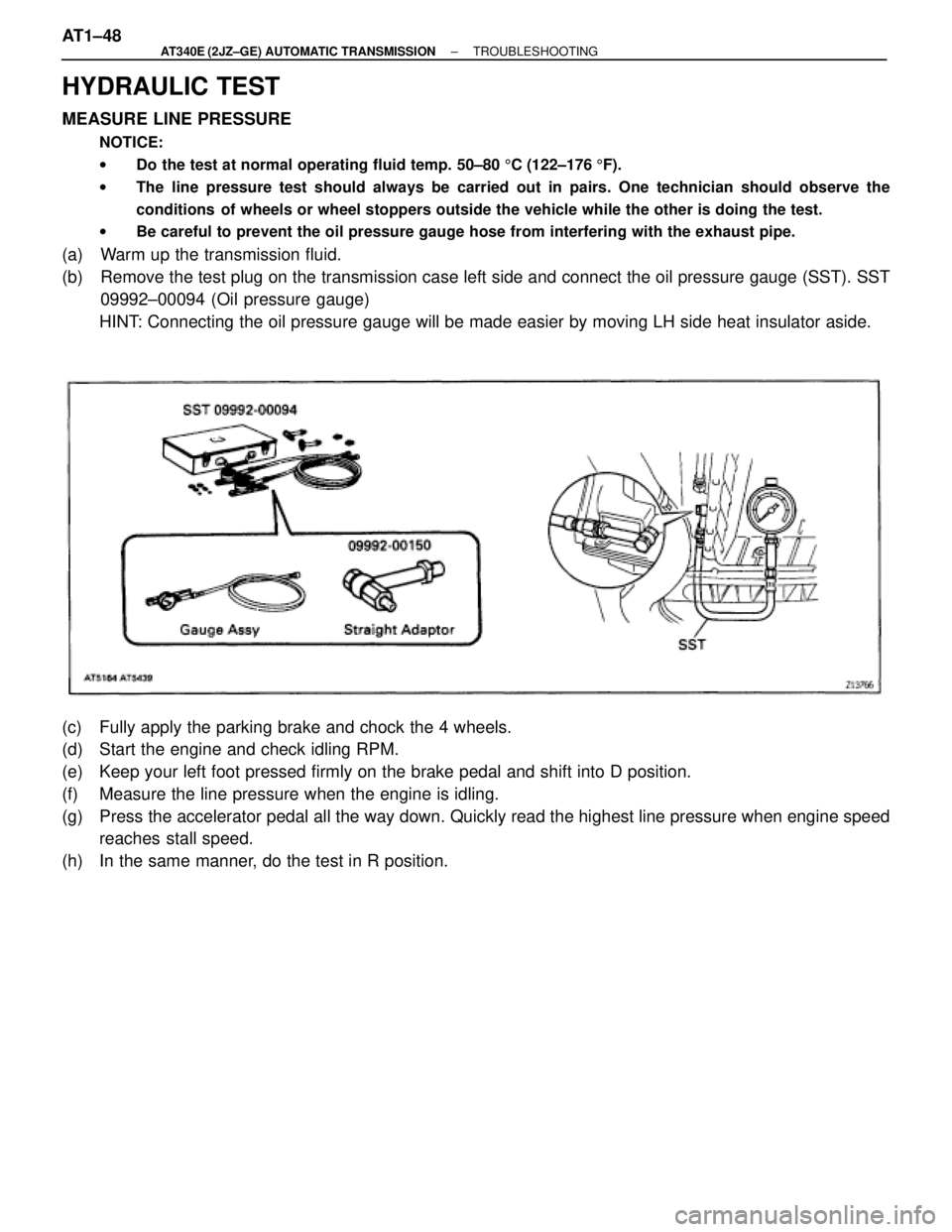
HYDRAULIC TEST
MEASURE LINE PRESSURE
NOTICE:
wDo the test at normal operating fluid temp. 50±80 5C (122±176 5F).
wThe line pressure test should always be carried out in pairs. One technician should observe the
conditions of wheels or wheel stoppers outside the vehicle while the other is doing the test.
wBe careful to prevent the oil pressure gauge hose from interfering with the exhaust pipe.
(a) Warm up the transmission fluid.
(b) Remove the test plug on the transmission case left side and connect the oil pressure gauge (SST). SST
09992±00094 (Oil pressure gauge)
HINT: Connecting the oil pressure gauge will be made easier by moving LH side heat insulator aside.
(c) Fully apply the parking brake and chock the 4 wheels.
(d) Start the engine and check idling RPM.
(e) Keep your left foot pressed firmly on the brake pedal and shift into D position.
(f) Measure the line pressure when the engine is idling.
(g) Press the accelerator pedal all the way down. Quickly read the highest line pressure when engine speed
reaches stall speed.
(h) In the same manner, do the test in R position. AT1±48
± AT340E (2JZ±GE) AUTOMATIC TRANSMISSIONTROUBLESHOOTING
Page 435 of 2543
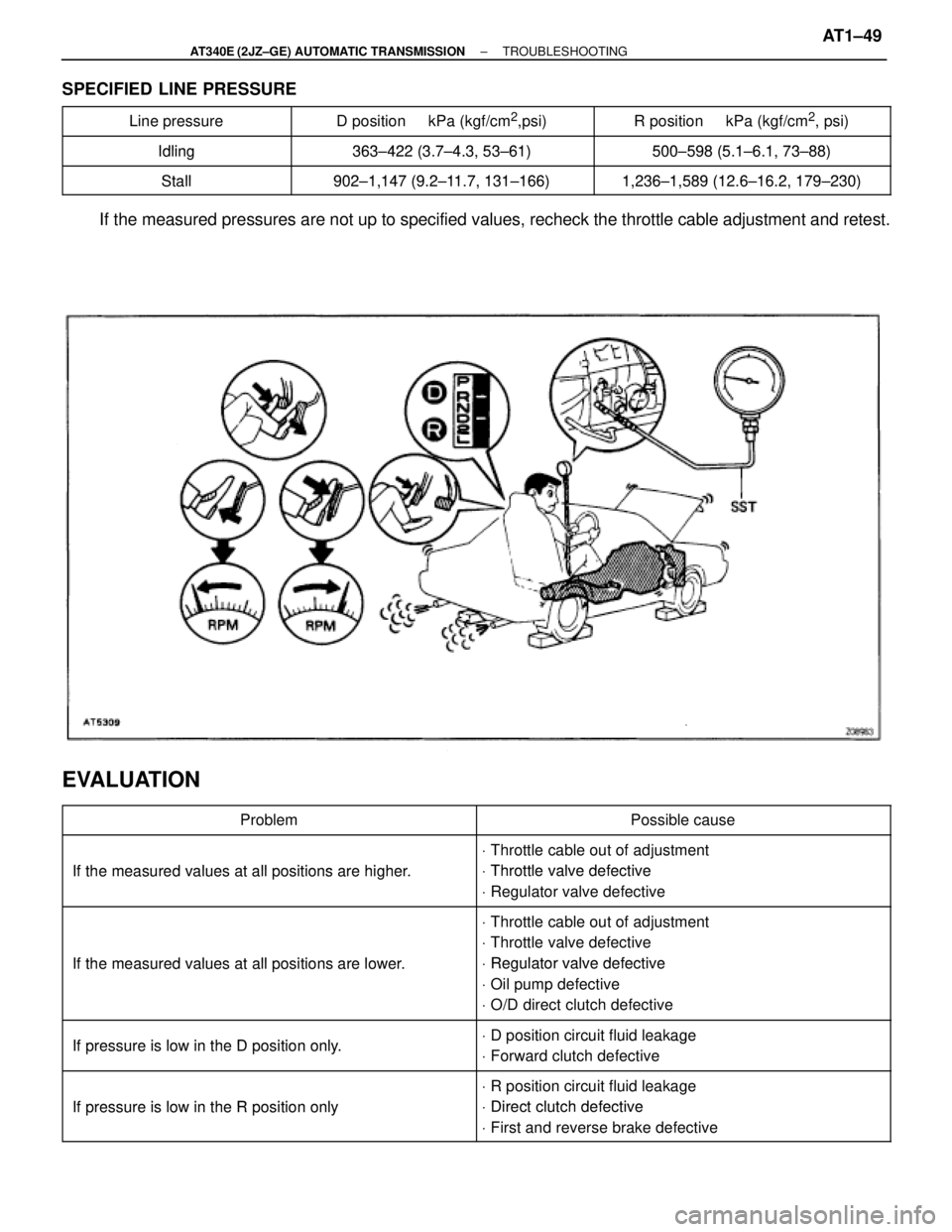
SPECIFIED LINE PRESSURE
����������� �����������Line pressure������������� �������������D position kPa (kgf/cm2,psi)�������������� ��������������R position kPa (kgf/cm2, psi)
����������� �����������Idling363 422 (3 7 4 3 53 61)500 598 (5 1 6 1 73 88)�����������Idling363±422 (3.7±4.3, 53±61)500±598 (5.1±6.1, 73±88)����������� �����������
Stall902 1 147 (9 2 11 7 131 166)1 236 1 589 (12 6 16 2 179 230)����������� �����������Stall902±1,147 (9.2±11.7, 131±166)1,236±1,589 (12.6±16.2, 179±230)
If the measured pressures are not up to specified values, recheck the throttle cable adjustment and retest.
EVALUATION
������������������ ������������������Problem������������������� �������������������Possible cause������������������ �
����������������� ������������������
If the measured values at allpositions are higher
V Throttle cable out of adjustment
Throttle valve defective������������������ ������������������ If the measured values at all positions are higher.V Throttle valve defective
V Regulator valve defective
������������������ �
����������������� �
����������������� ������������������If the measured values at allpositions are lower
V Throttle cable out of adjustment
V Throttle valve defective
Regulator valve defective������������������ �
����������������� ������������������
If the measured values at all positions are lower.V Regulator valve defective
V Oil pump defective
V O/D direct clutch defective
������������������ ������������������
Ifpressure is low in the Dposition onlyV D position circuit fluid leakage������������������ ������������������ If pressure is low in the D position only. D osition circuit fluid leakage
V Forward clutch defective������������������ �
����������������� ������������������Ifpressure is low in the Rposition only
V R position circuit fluid leakage
Direct clutch defective������������������ ������������������ If pressure is low in the R position onlyV Direct clutch defective
V First and reverse brake defective
± AT340E (2JZ±GE) AUTOMATIC TRANSMISSIONTROUBLESHOOTINGAT1±49
Page 438 of 2543
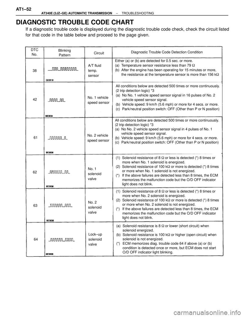
DTC
No.Blinking
PatternCircuitDiagnostic Trouble Code Detection Condition
38
42
Either (a) or (b) are detected for 0.5 sec. or more.
(a) Temperature sensor resistance less than 79 �
(b) After the engine has been operating for 15 minutes or more,
the resistance at the temperature sensor is more than 156 k�
All conditions below are detected 500 times or more continuously.
(2 trip detection logic) *3
(a) No No. 1 vehicle speed sensor signal in 16 pulses of No. 2
vehicle speed sensor signal.
(b) Vehicle speed: 9 km/h (5.6 mph) or more for 4 secs. or more.
(c) Park/neutral position switch: OFF (Other than P or N position)
A/T fluid
temp.
sensor
No. 1 vehicle
speed sensor
No. 2 vehicle
speed sensor
All conditions below are detected 500 times or more continuously.
(2 trip detection logic) *3
(a) No No. 2 vehicle speed sensor signal in 4 pulses of No. 1
vehicle speed sensor signal.
(b) Vehicle speed: 9 km/h (5.6 mph) or more for 4 secs. or more.
(c) Park/neutral position switch: OFF (Other than P or N position)
No. 1
solenoid
valve
(1) Solenoid resistance of 8 ��or less is detected (*) 8 times or
more when No. 1 solenoid is energized.
(2) Solenoid resistance of 100 k� or more is detected (*) 8 times
or more when No. 1 solenoid is not energized.
(*) If the above failures are detected less than 8 times, the ECM
memorizes the malfunction code but the O/D OFF indicator
light does not blink.
No. 2
solenoid
valve
(1) Solenoid resistance of 8 ��or less is detected (*) 8 times or
more when No. 2 solenoid is energized.
(2) Solenoid resistance of 100 k� or more is detected (*) 8 times
or more when No. 2 solenoid is not energized.
(*) If the above failures are detected less than 8 times, the ECM
memorizes the malfunction code but the O/D OFF indicator
light does not blink.
Lock±up
solenoid
valve
(a) Solenoid resistance is 8 ��or lower (short circuit) when
solenoid energized.
(b) Solenoid resistance is 100 k� or higher (open circuit) when
solenoid is not energized.
(*) ECM memorizes diag. trouble code 64 if above (a) or (b)
condition is detected once or more, but ECM does not start
O/D OFF indicator light blinking.
61
62
63
64
DIAGNOSTIC TROUBLE CODE CHART
If a diagnostic trouble code is displayed during the diagnostic trouble code check, check the circuit listed
for that code in the table below and proceed to the page given. AT1±52
± AT340E (2JZ±GE) AUTOMATIC TRANSMISSIONTROUBLESHOOTING
Page 451 of 2543
INSPECTION PROCEDURE
Check sensor resistance
Remove A/T fluid temp. sensor.
Measure resistance between terminals of A/T fluid
temp. sensor at 20°C (68°F) and 110°C (230°F).
Resistance:
20°C (68°F) Approx. 12.08 k�
110°C (230°F) Approx. 0.78 k�
Replace A/T fluid temp. sensor.
Repair or replace harness or connector.
Check harness and connector between battery and A/T fluid temp. sensor
A/T fluid temp. sensor and ECM. (See page IN±30).
Check A/T fluid temp. sensor.
Check and replace ECM. AT1±65
± AT340E (2JZ±GE) AUTOMATIC TRANSMISSIONTROUBLESHOOTING
Page 471 of 2543
Pattern Select Switch Circuit
CIRCUIT DESCRIPTION
The ECM memory contains the shift programs for the NORMAL and MANUAL patterns, 2 position, and L posi-
tion and the lock±up patterns. Following the programs corresponding to the signals from the pattern select
switch, the park/neutral position switch and other various sensors the ECM switches the solenoid valves ON
and OFF, thereby controlling the transmission gear change and the lock±up clutch operation.
WIRING DIAGRAM
INSPECTION PROCEDURE
Check A/T fluid temp. sensor. (See page AT1±64).
Replace A/T fluid temp. sensor.
± AT340E (2JZ±GE) AUTOMATIC TRANSMISSIONTROUBLESHOOTINGAT1±85