Page 472 of 2543
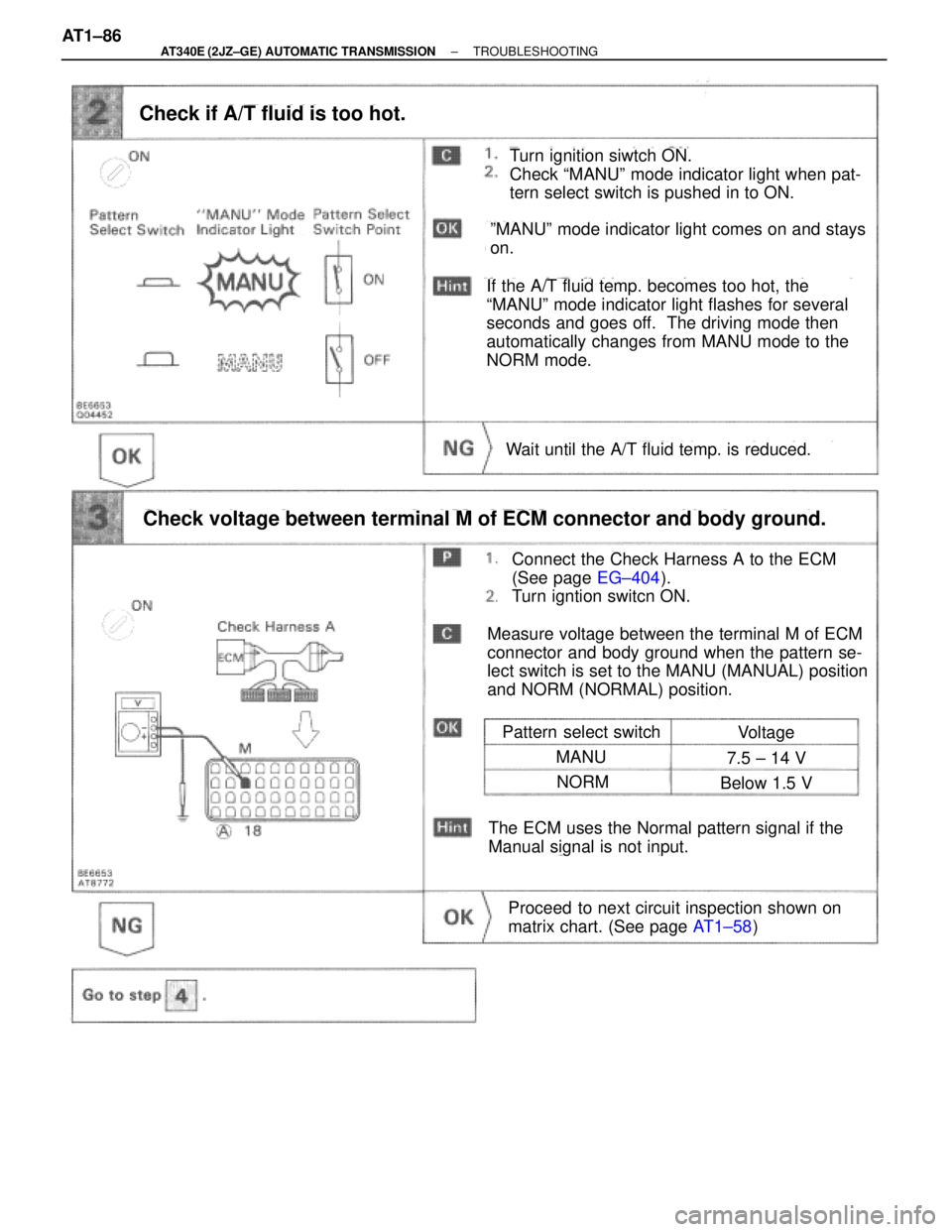
Turn ignition siwtch ON.
Check ªMANUº mode indicator light when pat-
tern select switch is pushed in to ON.
Check if A/T fluid is too hot.
Pattern select switch
Connect the Check Harness A to the ECM
(See page EG±404).
Turn igntion switcn ON.
Check voltage between terminal M of ECM connector and body ground.
Proceed to next circuit inspection shown on
matrix chart. (See page AT1±58)
Voltage
MANU7.5 ± 14 V
NORMBelow 1.5 V
Wait until the A/T fluid temp. is reduced.
The ECM uses the Normal pattern signal if the
Manual signal is not input.
Measure voltage between the terminal M of ECM
connector and body ground when the pattern se-
lect switch is set to the MANU (MANUAL) position
and NORM (NORMAL) position.
ºMANUº mode indicator light comes on and stays
on.
If the A/T fluid temp. becomes too hot, the
ªMANUº mode indicator light flashes for several
seconds and goes off. The driving mode then
automatically changes from MANU mode to the
NORM mode. AT1±86
± AT340E (2JZ±GE) AUTOMATIC TRANSMISSIONTROUBLESHOOTING
Page 497 of 2543
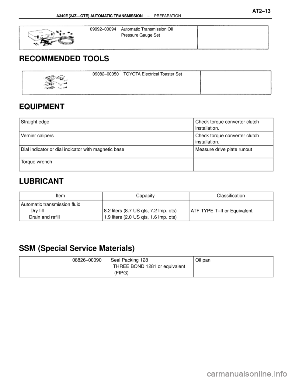
09992±00094 Automatic Transmission Oil
Pressure Gauge Set
09082±00050 TOYOTA Electrical Toaster Set
RECOMMENDED TOOLS
EQUIPMENT
������������������������� �������������������������Straight edge������������ ������������Check torque converter clutch
installation.
������������������������� �������������������������
Vernier calipersCheck torque converter clutch������������������������� �������������������������Vernier cali ersCheck torque converter clutch
installation.������������������������� �
������������������������ �������������������������Dial indicator or dial indicator with magnetic baseMeasure drive plate runout
�������������������������������������������������� �
������������������������ �������������������������
Torque wrench
LUBRICANT
������������ ������������Item������������� �������������Capacity������������� �������������Classification
������������ ������������Automatic transmission fluid
Dry fill8 2 liters (8 7 US qts 7 2 lmpqts)ATF TYPE T II or Equivalent������������ �
����������� ������������
Dry fill
Drain and refill
8.2 liters (8.7 US qts, 7.2 lmp. qts)
1.9 liters (2.0 US qts, 1.6 lmp. qts)
ATF TYPE T±II or Equivalent
SSM (Special Service Materials)
������������������������� �
������������������������ �
������������������������ �������������������������
08826±00090 Seal Packing 128
THREE BOND 1281 or equivalent
(FIPG)������������ �
����������� �
����������� ������������
Oil pan
± A340E (2JZÐGTE) AUTOMATIC TRANSMISSIONPREPARATIONAT2±13
Page 499 of 2543
(b) Install the output flange and 2 washers.
(c) Install and torque a new nut.
Torque: 123 NVm (1.250 kgfVcm, 90 ftVlbf)
HINT: Shift the shift lever to the P position
(d) Using a hammer and chisel, stake the nut.
8. INSTALL PROPELLER SHAFT
(See page PR±13)
9. INSTALL FRONT EXHAUST PIPE AND HEAT INSULATOR
(See page AT2±22)
10. FILL AND CHECK A/T FLUID (See page AT2±42)
A/T FLUID TEMP. SENSOR
REPLACEMENT
1. DISCONNECT A/T FLUID TEMP. SENSOR CONNECTOR
2. REMOVE A/T FLUID TEMP. SENSOR
(a) Remove the A/T fluid temp. sensor.
(b) Remove the O±ring from it.
3. INSTALL A/T FLUID TEMP. SENSOR
(a) Coat a new O±ring with A/T fluid and install it to the A/T fluid
temp. sensor
(b) Install the A/T fluid temp. sensor.
Torque: 15 NVm (150 kgfVcm, 11 ftVlbf)
4. CONNECT A/T FLUID TEMP. SENSOR CONNECTOR
± A340E (2JZÐGTE) AUTOMATIC TRANSMISSIONON±VEHICLE REPAIRAT2±15
Page 502 of 2543
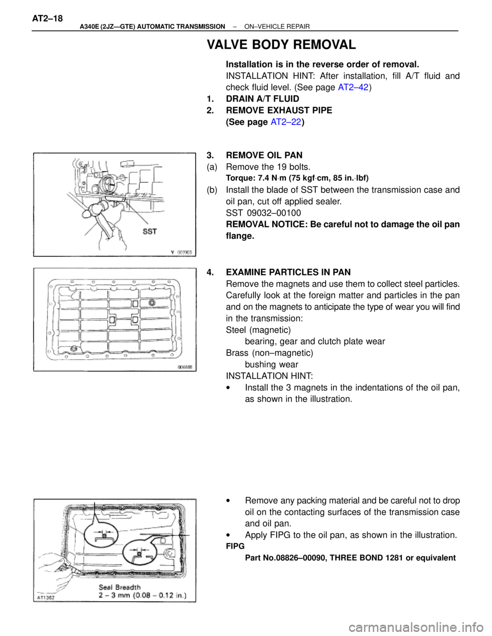
VALVE BODY REMOVAL
Installation is in the reverse order of removal.
INSTALLATION HINT: After installation, fill A/T fluid and
check fluid level. (See page AT2±42)
1. DRAIN A/T FLUID
2. REMOVE EXHAUST PIPE
(See page AT2±22)
3. REMOVE OIL PAN
(a) Remove the 19 bolts.
Torque: 7.4 NVm (75 kgfVcm, 85 in.Vlbf)
(b) Install the blade of SST between the transmission case and
oil pan, cut off applied sealer.
SST 09032±00100
REMOVAL NOTICE: Be careful not to damage the oil pan
flange.
4. EXAMINE PARTICLES IN PAN
Remove the magnets and use them to collect steel particles.
Carefully look at the foreign matter and particles in the pan
and on the magnets to anticipate the type of wear you will find
in the transmission:
Steel (magnetic)
bearing, gear and clutch plate wear
Brass (non±magnetic)
bushing wear
INSTALLATION HINT:
wInstall the 3 magnets in the indentations of the oil pan,
as shown in the illustration.
wRemove any packing material and be careful not to drop
oil on the contacting surfaces of the transmission case
and oil pan.
wApply FIPG to the oil pan, as shown in the illustration.
FIPG
Part No.08826±00090, THREE BOND 1281 or equivalent
AT2±18± A340E (2JZÐGTE) AUTOMATIC TRANSMISSIONON±VEHICLE REPAIR
Page 506 of 2543
TRANSMISSION REMOVAL
Installation is in the reverse order of removal.
INSTALLATION HINT: After installation, fill A/T fluid and
check fluid level. (See page AT2±42)
1. REMOVE LEVEL GAUGE
2. REMOVE FILLER PIPE
Remove the bolt and filler pipe.
3. REMOVE ENGINE UNDER COVER
4. DISCONNECT OXYGEN SENSOR
(a) Remove the 2 nuts.
(b) Remove the cover and the sensor.
5. REMOVE EXHAUST PIPE
(a) Remove the 2 nuts and 4 bolts.
(b) Disconnect the rings from the exhaust pipe brackets.
(c) Remove the exhaust pipe, gasket and bracket.
Torque:
Bracket X Transmission housing:
37 NVm (380 kgfVcm, 27 ftVlbf)
No.2 exhaust pipe X Center exhaust pipe:
58 NVm (590 kgfVcm, 43 ftVlbf)
6. REMOVE HEAT INSULATOR
Torque: 5.4 NVm (55 kgfVcm, 48 in.Vlbf)
AT2±22± A340E (2JZÐGTE) AUTOMATIC TRANSMISSIONASSEMBLY REMOVAL AND INSTALLATION
Page 521 of 2543
PROBLEM SYMPTOM CONFIRMATION
Taking into consideration the results of the customer problem analysis, try to reproduce the symptoms of
the trouble. If the problem is that the transmission does not up±shift, does not down±shift, or the shift point
is too high or too low, conduct the following road test to confirm the automatic shift schedule and simulate
the problem symptoms.
ROAD TEST
NOTICE: Do the test at normal A/T fluid operating temp.
50±805C (122±1765F).
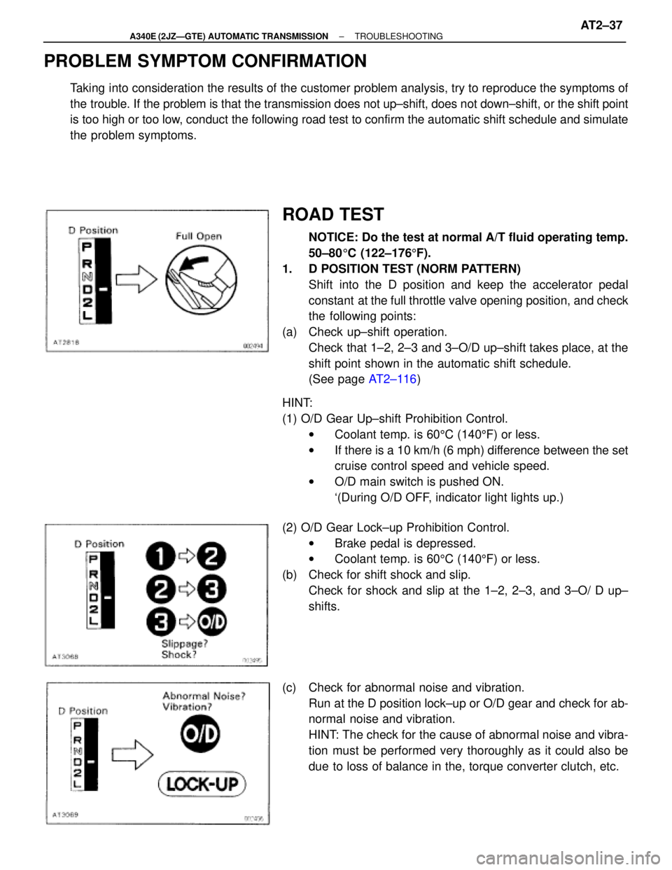
1. D POSITION TEST (NORM PATTERN)
Shift into the D position and keep the accelerator pedal
constant at the full throttle valve opening position, and check
the following points:
(a) Check up±shift operation.
Check that 1±2, 2±3 and 3±O/D up±shift takes place, at the
shift point shown in the automatic shift schedule.
(See page AT2±116)
HINT:
(1) O/D Gear Up±shift Prohibition Control.
wCoolant temp. is 605C (1405F) or less.
wIf there is a 10 km/h (6 mph) difference between the set
cruise control speed and vehicle speed.
wO/D main switch is pushed ON.
`(During O/D OFF, indicator light lights up.)
(2) O/D Gear Lock±up Prohibition Control.
wBrake pedal is depressed.
wCoolant temp. is 605C (1405F) or less.
(b) Check for shift shock and slip.
Check for shock and slip at the 1±2, 2±3, and 3±O/ D up±
shifts.
(c) Check for abnormal noise and vibration.
Run at the D position lock±up or O/D gear and check for ab-
normal noise and vibration.
HINT: The check for the cause of abnormal noise and vibra-
tion must be performed very thoroughly as it could also be
due to loss of balance in the, torque converter clutch, etc.
± A340E (2JZÐGTE) AUTOMATIC TRANSMISSIONTROUBLESHOOTINGAT2±37
Page 526 of 2543
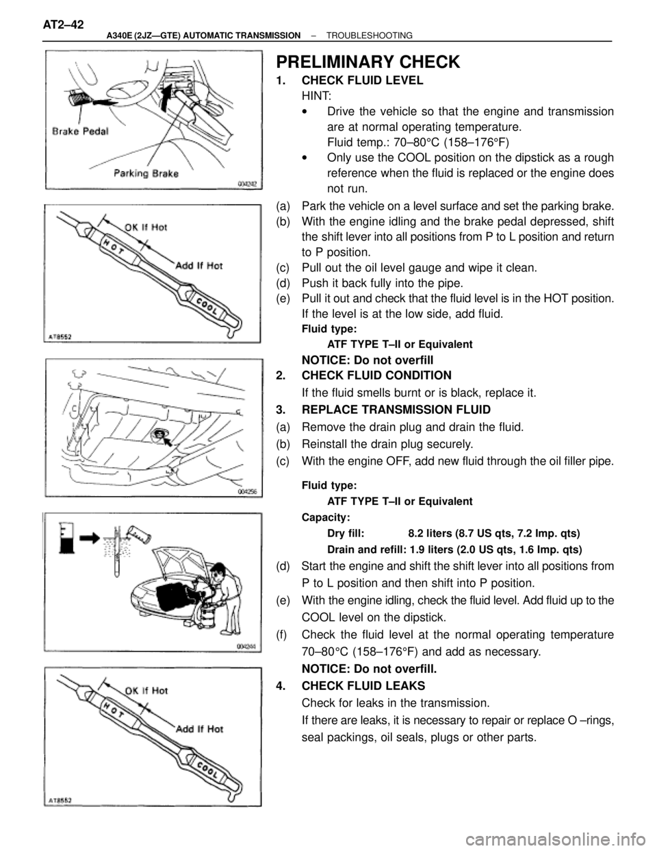
PRELIMINARY CHECK
1. CHECK FLUID LEVEL
HINT:
wDrive the vehicle so that the engine and transmission
are at normal operating temperature.
Fluid temp.: 70±805C (158±1765F)
wOnly use the COOL position on the dipstick as a rough
reference when the fluid is replaced or the engine does
not run.
(a) Park the vehicle on a level surface and set the parking brake.
(b) With the engine idling and the brake pedal depressed, shift
the shift lever into all positions from P to L position and return
to P position.
(c) Pull out the oil level gauge and wipe it clean.
(d) Push it back fully into the pipe.
(e) Pull it out and check that the fluid level is in the HOT position.
If the level is at the low side, add fluid.
Fluid type:
ATF TYPE T±II or Equivalent
NOTICE: Do not overfill
2. CHECK FLUID CONDITION
If the fluid smells burnt or is black, replace it.
3. REPLACE TRANSMISSION FLUID
(a) Remove the drain plug and drain the fluid.
(b) Reinstall the drain plug securely.
(c) With the engine OFF, add new fluid through the oil filler pipe.
Fluid type:
ATF TYPE T±II or Equivalent
Capacity:
Dry fill: 8.2 liters (8.7 US qts, 7.2 Imp. qts)
Drain and refill: 1.9 liters (2.0 US qts, 1.6 Imp. qts)
(d) Start the engine and shift the shift lever into all positions from
P to L position and then shift into P position.
(e) With the engine idling, check the fluid level. Add fluid up to the
COOL level on the dipstick.
(f) Check the fluid level at the normal operating temperature
70±805C (158±1765F) and add as necessary.
NOTICE: Do not overfill.
4. CHECK FLUID LEAKS
Check for leaks in the transmission.
If there are leaks, it is necessary to repair or replace O ±rings,
seal packings, oil seals, plugs or other parts. AT2±42
± A340E (2JZÐGTE) AUTOMATIC TRANSMISSIONTROUBLESHOOTING
Page 528 of 2543
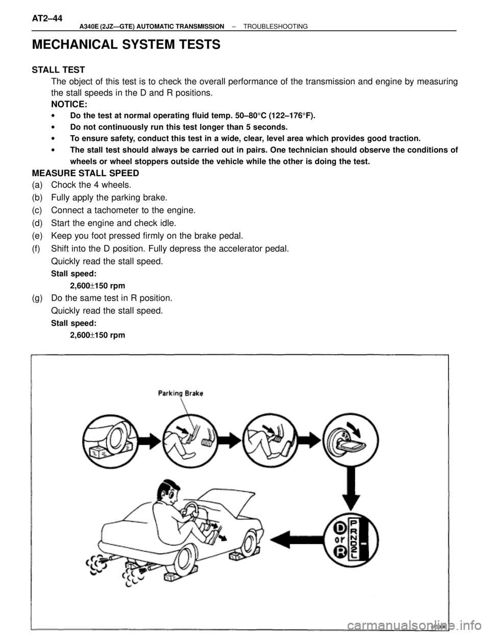
MECHANICAL SYSTEM TESTS
STALL TEST
The object of this test is to check the overall performance of the transmission and engine by measuring
the stall speeds in the D and R positions.
NOTICE:
wDo the test at normal operating fluid temp. 50±805C (122±1765F).
wDo not continuously run this test longer than 5 seconds.
wTo ensure safety, conduct this test in a wide, clear, level area which provides good traction.
wThe stall test should always be carried out in pairs. One technician should observe the conditions of
wheels or wheel stoppers outside the vehicle while the other is doing the test.
MEASURE STALL SPEED
(a) Chock the 4 wheels.
(b) Fully apply the parking brake.
(c) Connect a tachometer to the engine.
(d) Start the engine and check idle.
(e) Keep you foot pressed firmly on the brake pedal.
(f) Shift into the D position. Fully depress the accelerator pedal.
Quickly read the stall speed.
Stall speed:
2,600+150 rpm
(g) Do the same test in R position.
Quickly read the stall speed.
Stall speed:
2,600+150 rpm
AT2±44± A340E (2JZÐGTE) AUTOMATIC TRANSMISSIONTROUBLESHOOTING