Page 1335 of 2543

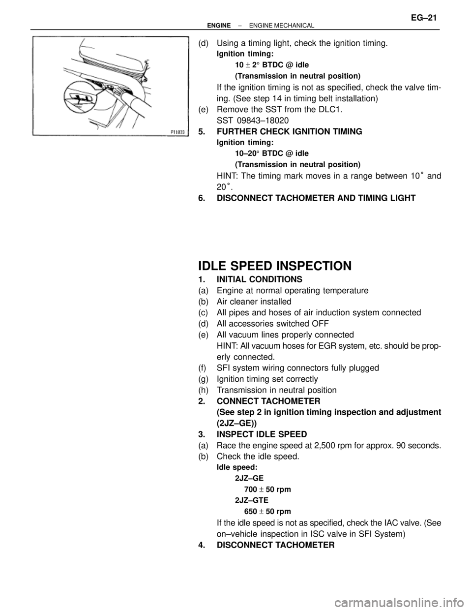
(d) Using a timing light, check the ignition timing.
Ignition timing:
10 + 25 BTDC @ idle
(Transmission in neutral position)
If the ignition timing is not as specified, check the valve tim-
ing. (See step 14 in timing belt installation)
(e) Remove the SST from the DLC1.
SST 09843±18020
5. FURTHER CHECK IGNITION TIMING
Ignition timing:
10±205 BTDC @ idle
(Transmission in neutral position)
HINT: The timing mark moves in a range between 10° and
20°.
6. DISCONNECT TACHOMETER AND TIMING LIGHT
IDLE SPEED INSPECTION
1. INITIAL CONDITIONS
(a) Engine at normal operating temperature
(b) Air cleaner installed
(c) All pipes and hoses of air induction system connected
(d) All accessories switched OFF
(e) All vacuum lines properly connected
HINT: All vacuum hoses for EGR system, etc. should be prop-
erly connected.
(f) SFI system wiring connectors fully plugged
(g) Ignition timing set correctly
(h) Transmission in neutral position
2. CONNECT TACHOMETER
(See step 2 in ignition timing inspection and adjustment
(2JZ±GE))
3. INSPECT IDLE SPEED
(a) Race the engine speed at 2,500 rpm for approx. 90 seconds.
(b) Check the idle speed.
Idle speed:
2JZ±GE
700 + 50 rpm
2JZ±GTE
650 + 50 rpm
If the idle speed is not as specified, check the IAC valve. (See
on±vehicle inspection in ISC valve in SFI System)
4. DISCONNECT TACHOMETER
± ENGINEENGINE MECHANICALEG±21
Page 1336 of 2543
TIMING BELT
COMPONENTS FOR REMOVAL AND
INSTALLATION
EG±22± ENGINEENGINE MECHANICAL
Page 1337 of 2543
± ENGINEENGINE MECHANICALEG±23
Page 1338 of 2543
TIMING BELT REMOVAL
1. REMOVE RADIATOR ASSEMBLY
(See radiator removal in Cooling System)
2. 2JZ±GTE M/T:
REMOVE DRIVE BELT TENSIONER DAMPER
Remove the 2 nuts and tensioner damper.
3. REMOVE DRIVE BELT, FAN, FLUID COUPLING
ASSEMBLY AND WATER PUMP PULLEY
(See step 6 in water pump removal in Cooling System)
4. REMOVE NO.3 TIMING BELT COVER
(a) Remove the oil filler cap.
(b) 2JZ±GE:
Using a 5 mm hexagon wrench, remove the 6 bolts and belt
cover.
(c) 2JZ±GTE:
Using a 5 mm hexagon wrench, remove the 10 bolts and belt
cover.
5. REMOVE NO.2 TIMING BELT COVER
Using a 5 mm hexagon wrench, remove the 3 bolts, belt cover
and gasket.
If you are unable to loosen the bolt on the right because the
PS pump pulley interferes with the hexagon wrench, first re-
move the pulley.
6. REMOVE DRIVE BELT TENSIONER
Remove the 3 bolts and tensioner. EG±24
± ENGINEENGINE MECHANICAL
Page 1339 of 2543
7. SET NO.1 CYLINDER TO TDC/COMPRESSION
(a) Turn the crankshaft pulley, and align its groove with timing
mark ºOº of the No.1 timing belt cover.
NOTICE: Always turn the crankshaft clockwise.
(b) Check that the timing marks of the camshaft timing pulleys
are aligned with the timing marks of the No.4 timing belt
cover.
If not, turn the crankshaft 1 revolution (360°).
8. REMOVE TIMING BELT FROM CAMSHAFT TIMING
PULLEYS
HINT (Re±using timing belt): Place matchmarks on the timing
belt and camshaft timing pulleys as shown in the illustration.
(a) Alternately loosen the 2 bolts, and remove them, the
tensioner and dust boot.
(b) Disconnect the timing belt from the camshaft timing pulleys.
± ENGINEENGINE MECHANICALEG±25
Page 1340 of 2543
9. REMOVE CAMSHAFT TIMING PULLEYS
Using SST, remove the pulley bolt. Remove the 2 timing pul-
leys.
SST 09960±10010 (09962±01000, 09963±01000)
10. A/T:
DISCONNECT OIL COOLER TUBES
Remove the 2 bolts and hose clamps, and disconnect oil
cooler tubes.
11. REMOVE CRANKSHAFT PULLEY
(a) Using SST, loosen the pulley bolt.
SST 09213±70010, 09330±00021
(b) Remove the pulley bolt.
(c) Using SST, remove the pulley.
SST 09950±50010 (09954±05030, 09551±05010,
09552±05010, 09553±05020)
12. 2JZ±GE:
REMOVE PS PUMP FRONT BRACKET
Remove the 3 bolts, plate washer and pump front bracket. EG±26
± ENGINEENGINE MECHANICAL
Page 1341 of 2543
13. REMOVE NO.1 TIMING BELT COVER
Remove the 5 bolts, timing belt cover and gasket.
14. REMOVE TIMING BELT GUIDE
15. REMOVE TIMING BELT
HINT (When re±using timing belt): Draw an arrow on the tim-
ing belt in the direction of engine revolution, and place match-
marks on the timing belt and crankshaft timing pulley.
16. REMOVE IDLER PULLEY
Using a 10 mm hexagon wrench, remove the pivot bolt, plate
washer and idler pulley.
17. REMOVE CRANKSHAFT TIMING PULLEY
(a) 2JZ±GTE:
Remove the bolt and timing belt plate.
(b) Remove the crankshaft timing pulley.
If the pulley cannot be removed by hand, use SST to remove
the crankshaft timing pulley.
SST 09950±50010 (09951±05010, 09952±05010,
09953±05020, 09954±00010)
± ENGINEENGINE MECHANICALEG±27
Page 1342 of 2543

TIMING BELT COMPONENTS
INSPECTION
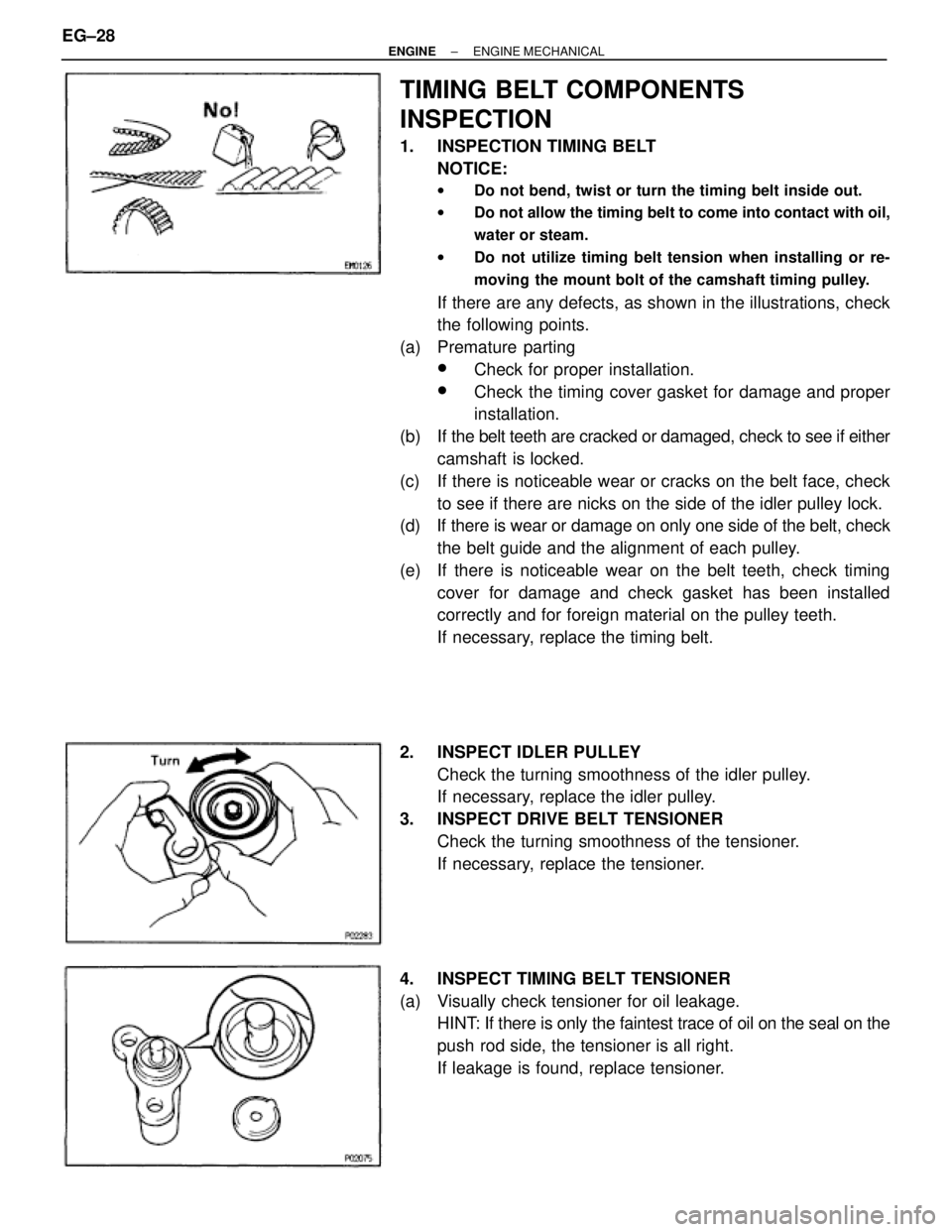
1. INSPECTION TIMING BELT
NOTICE:
wDo not bend, twist or turn the timing belt inside out.
wDo not allow the timing belt to come into contact with oil,
water or steam.
wDo not utilize timing belt tension when installing or re-
moving the mount bolt of the camshaft timing pulley.
If there are any defects, as shown in the illustrations, check
the following points.
(a) Premature parting
wCheck for proper installation.
wCheck the timing cover gasket for damage and proper
installation.
(b) If the belt teeth are cracked or damaged, check to see if either
camshaft is locked.
(c) If there is noticeable wear or cracks on the belt face, check
to see if there are nicks on the side of the idler pulley lock.
(d) If there is wear or damage on only one side of the belt, check
the belt guide and the alignment of each pulley.
(e) If there is noticeable wear on the belt teeth, check timing
cover for damage and check gasket has been installed
correctly and for foreign material on the pulley teeth.
If necessary, replace the timing belt.
2. INSPECT IDLER PULLEY
Check the turning smoothness of the idler pulley.
If necessary, replace the idler pulley.
3. INSPECT DRIVE BELT TENSIONER
Check the turning smoothness of the tensioner.
If necessary, replace the tensioner.
4. INSPECT TIMING BELT TENSIONER
(a) Visually check tensioner for oil leakage.
HINT: If there is only the faintest trace of oil on the seal on the
push rod side, the tensioner is all right.
If leakage is found, replace tensioner. EG±28
± ENGINEENGINE MECHANICAL