Page 1327 of 2543

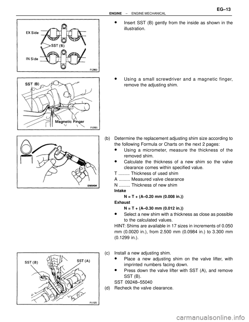
wInsert SST (B) gently from the inside as shown in the
illustration.
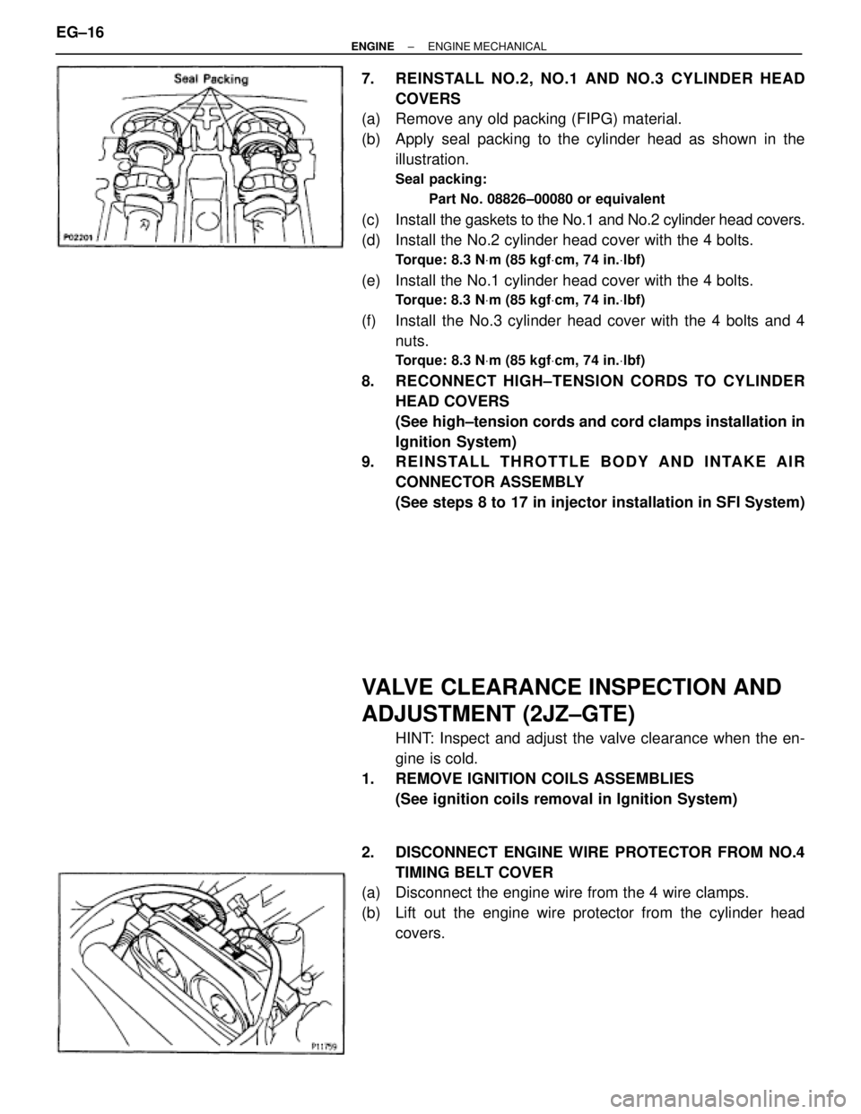
wUsing a small screwdriver and a magnetic finger,
remove the adjusting shim.
(b) Determine the replacement adjusting shim size according to
the following Formula or Charts on the next 2 pages:
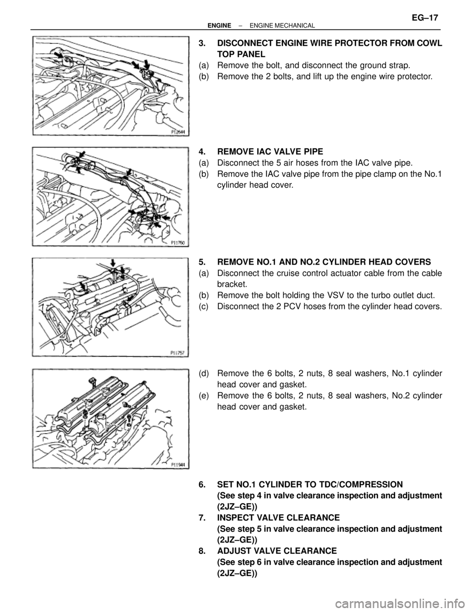
wUsing a micrometer, measure the thickness of the
removed shim.
wCalculate the thickness of a new shim so the valve
clearance comes within specified value.
T ......... Thickness of used shim
A ......... Measured valve clearance
N ......... Thickness of new shim
Intake
N = T + (A±0.20 mm (0.008 in.))
Exhaust
N = T + (A±0.30 mm (0.012 in.))
wSelect a new shim with a thickness as close as possible
to the calculated values.
HINT: Shims are available in 17 sizes in increments of 0.050
mm (0.0020 in.), from 2.500 mm (0.0984 in.) to 3.300 mm
(0.1299 in.).
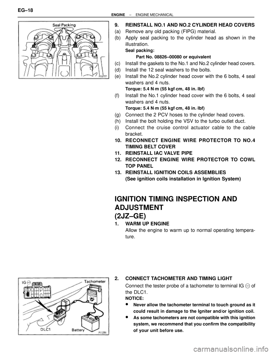
(c) Install a new adjusting shim.
wPlace a new adjusting shim on the valve lifter, with
imprinted numbers facing down.
wPress down the valve lifter with SST (A), and remove
SST (B).
SST 09248±55040
(d) Recheck the valve clearance.
± ENGINEENGINE MECHANICALEG±13
Page 1328 of 2543
EG±14± ENGINEENGINE MECHANICAL
Page 1329 of 2543
± ENGINEENGINE MECHANICALEG±15
Page 1330 of 2543

7. REINSTALL NO.2, NO.1 AND NO.3 CYLINDER HEAD
COVERS
(a) Remove any old packing (FIPG) material.
(b) Apply seal packing to the cylinder head as shown in the
illustration.
Seal packing:
Part No. 08826±00080 or equivalent
(c) Install the gaskets to the No.1 and No.2 cylinder head covers.
(d) Install the No.2 cylinder head cover with the 4 bolts.
Torque: 8.3 NVm (85 kgfVcm, 74 in.Vlbf)
(e) Install the No.1 cylinder head cover with the 4 bolts.
Torque: 8.3 NVm (85 kgfVcm, 74 in.Vlbf)
(f) Install the No.3 cylinder head cover with the 4 bolts and 4
nuts.
Torque: 8.3 NVm (85 kgfVcm, 74 in.Vlbf)
8. RECONNECT HIGH±TENSION CORDS TO CYLINDER
HEAD COVERS
(See high±tension cords and cord clamps installation in
Ignition System)
9. REINSTALL THROTTLE BODY AND INTAKE AIR
CONNECTOR ASSEMBLY
(See steps 8 to 17 in injector installation in SFI System)
VALVE CLEARANCE INSPECTION AND
ADJUSTMENT (2JZ±GTE)
HINT: Inspect and adjust the valve clearance when the en-
gine is cold.
1. REMOVE IGNITION COILS ASSEMBLIES
(See ignition coils removal in Ignition System)
2. DISCONNECT ENGINE WIRE PROTECTOR FROM NO.4
TIMING BELT COVER
(a) Disconnect the engine wire from the 4 wire clamps.
(b) Lift out the engine wire protector from the cylinder head
covers. EG±16
± ENGINEENGINE MECHANICAL
Page 1331 of 2543

3. DISCONNECT ENGINE WIRE PROTECTOR FROM COWL
TOP PANEL
(a) Remove the bolt, and disconnect the ground strap.
(b) Remove the 2 bolts, and lift up the engine wire protector.
4. REMOVE IAC VALVE PIPE
(a) Disconnect the 5 air hoses from the IAC valve pipe.
(b) Remove the IAC valve pipe from the pipe clamp on the No.1
cylinder head cover.
5. REMOVE NO.1 AND NO.2 CYLINDER HEAD COVERS
(a) Disconnect the cruise control actuator cable from the cable
bracket.
(b) Remove the bolt holding the VSV to the turbo outlet duct.
(c) Disconnect the 2 PCV hoses from the cylinder head covers.
(d) Remove the 6 bolts, 2 nuts, 8 seal washers, No.1 cylinder
head cover and gasket.
(e) Remove the 6 bolts, 2 nuts, 8 seal washers, No.2 cylinder
head cover and gasket.
6. SET NO.1 CYLINDER TO TDC/COMPRESSION
(See step 4 in valve clearance inspection and adjustment
(2JZ±GE))
7. INSPECT VALVE CLEARANCE
(See step 5 in valve clearance inspection and adjustment
(2JZ±GE))
8. ADJUST VALVE CLEARANCE
(See step 6 in valve clearance inspection and adjustment
(2JZ±GE))
± ENGINEENGINE MECHANICALEG±17
Page 1332 of 2543

9. REINSTALL NO.1 AND NO.2 CYLINDER HEAD COVERS
(a) Remove any old packing (FIPG) material.
(b) Apply seal packing to the cylinder head as shown in the
illustration.
Seal packing:
Part No. 08826±00080 or equivalent
(c) Install the gaskets to the No.1 and No.2 cylinder head covers.
(d) Install the 12 seal washers to the bolts.
(e) Install the No.2 cylinder head cover with the 6 bolts, 4 seal
washers and 4 nuts.
Torque: 5.4 NVm (55 kgfVcm, 48 in.Vlbf)
(f) Install the No.1 cylinder head cover with the 6 bolts, 4 seal
washers and 4 nuts.
Torque: 5.4 NVm (55 kgfVcm, 48 in.Vlbf)
(g) Connect the 2 PCV hoses to the cylinder head covers.
(h) Install the bolt holding the VSV to the turbo outlet duct.
(i) Connect the cruise control actuator cable to the cable
bracket.
10. RECONNECT ENGINE WIRE PROTECTOR TO NO.4
TIMING BELT COVER
11. REINSTALL IAC VALVE PIPE
12. RECONNECT ENGINE WIRE PROTECTOR TO COWL
TOP PANEL
13. REINSTALL IGNITION COILS ASSEMBLIES
(See ignition coils installation in Ignition System)
IGNITION TIMING INSPECTION AND
ADJUSTMENT
(2JZ±GE)
1. WARM UP ENGINE
Allow the engine to warm up to normal operating tempera-
ture.
2. CONNECT TACHOMETER AND TIMING LIGHT
Connect the tester probe of a tachometer to terminal IG � of
the DLC1.
NOTICE:
wNever allow the tachometer terminal to touch ground as it
could result in damage to the Igniter and/or ignition coil.
wAs some tachometers are not compatible with this ignition
system, we recommend that you confirm the compatibility
of your unit before use.
EG±18± ENGINEENGINE MECHANICAL
Page 1333 of 2543
3. CHECK IDLE SPEED
(a) Race the engine speed at 2,500 rpm for approx. 90 seconds.
(b) Check the idle speed.
Idle speed:
700 + 50 rpm
4. ADJUST IGNITION TIMING
(a) Using SST, connect terminals TE1 and E1 of the DLC 1.
SST 09843±18020
(b) Using a timing light, check the ignition timing.
Ignition timing:
10 + 2° BTDC @ idle
(Transmission in neutral position)
(c) Loosen the nut, and adjust by turning the distributor.
Ignition timing:
10° BTDC @ idle
(Transmission in neutral position)
(d) Tighten the nut, and recheck the ignition timing.
Torque: 19 NVm (195 kgfVcm, 14 ftVlbf)
(e) Remove the SST from the DLC1.
SST 09843±18020
5. FURTHER CHECK IGNITION TIMING
Ignition timing:
7±19° BTDC @ idle
(Transmission in neutral position)
HINT: The timing mark moves in a range between 75 and 195.
6. DISCONNECT TACHOMETER AND TIMING LIGHT
± ENGINEENGINE MECHANICALEG±19
Page 1334 of 2543
IGNITION TIMING INSPECTION
(2JZ±GTE)
1. WARM UP ENGINE
Allow the engine to warm up to normal operating tempera-
ture.
2. CONNECT TACHOMETER AND TIMING LIGHT
(See step 2 in ignition timing inspection and adjustment
(2JZ±GE))
3. CHECK IDLE SPEED
(a) Race the engine speed at 2,500 rpm for approx. 90 seconds.
(b) Check the idle speed.
Idle speed:
650 + 50 rpm
4. CHECK IGNITION TIMING
(a) Using SST, connect terminals TE1 and E1 of the DLC 1.
SST 09843±18020
(b) Open the igniter connector cover and remove the green lead
wire.
(c) Connect the timing light clip to the green lead wire.
NOTICE:
wUse a timing light that can detect the primary signal.
wAfter finishing the inspection, make sure the lead wire is
stored inside the connector cover.
EG±20± ENGINEENGINE MECHANICAL