Page 1135 of 2543

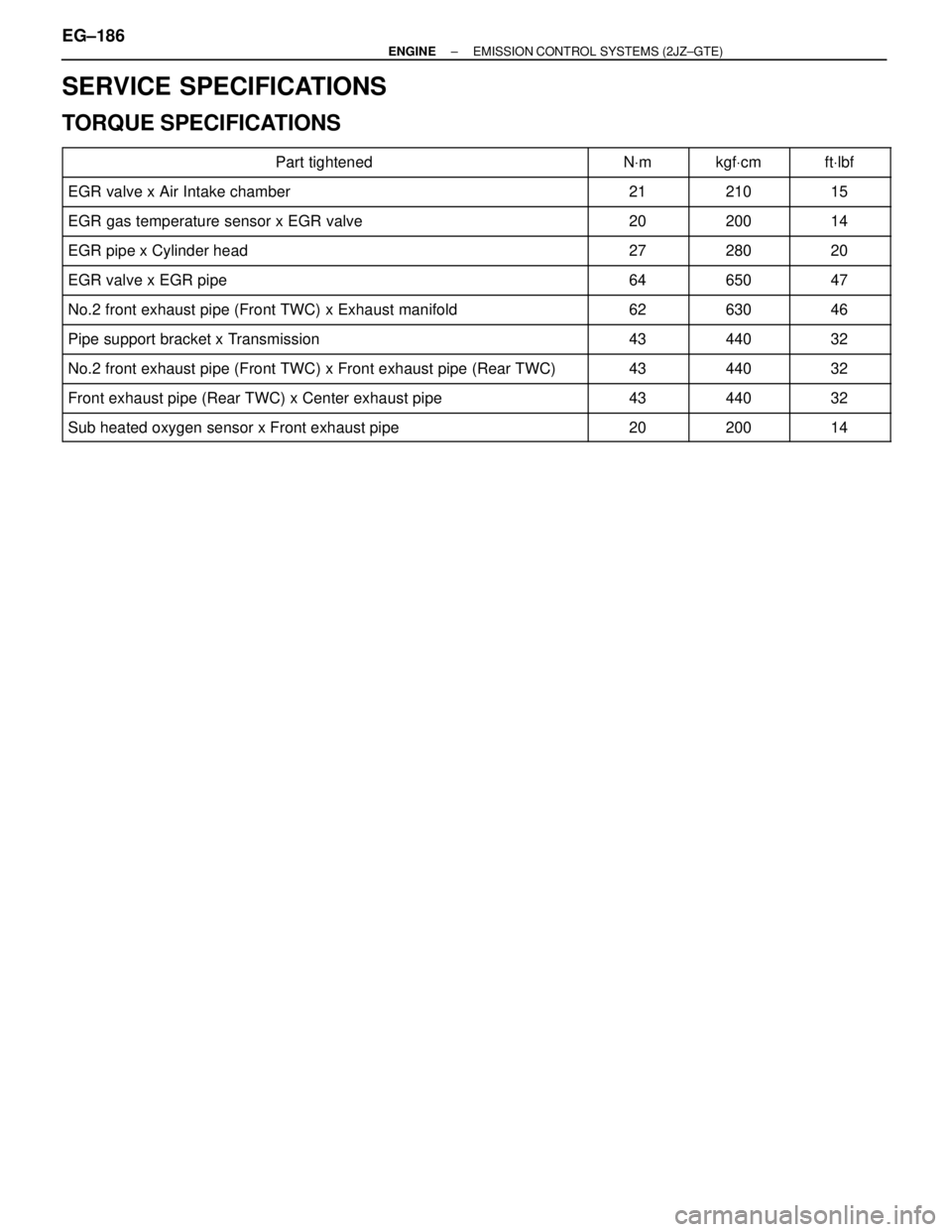
SERVICE SPECIFICATIONS
TORQUE SPECIFICATIONS
����������������������� �����������������������Part tightened����� �����NVm������ ������kgfVcm����� �����ftVlbf
����������������������� �����������������������EGR valve x Air Intake chamber����� �����21������ ������210����� �����15
����������������������� �����������������������EGR gas temperature sensor x EGR valve����� �����20������ ������200����� �����14����������������������� �
���������������������� �����������������������EGR pipe x Cylinder head
����� �
���� �����27
������ �
����� ������280
����� �
���� �����20
����������������������� �����������������������EGR valve x EGR pipe����� �����64������ ������650����� �����47
����������������������� �����������������������No.2 front exhaust pipe (Front TWC) x Exhaust manifold����� �����62������ ������630����� �����46
����������������������� �����������������������Pipe support bracket x Transmission����� �����43������ ������440����� �����32����������������������� �
���������������������� �����������������������No.2 front exhaust pipe (Front TWC) x Front exhaust pipe (Rear TWC)����� �
���� �����43������ �
����� ������440����� �
���� �����32
����������������������� �����������������������Front exhaust pipe (Rear TWC) x Center exhaust pipe����� �����43������ ������440����� �����32
����������������������� �����������������������Sub heated oxygen sensor x Front exhaust pipe����� �����20������ ������200����� �����14
EG±186± ENGINEEMISSION CONTROL SYSTEMS (2JZ±GTE)
Page 1156 of 2543

ON±VEHICLE INSPECTION
SPARK TEST
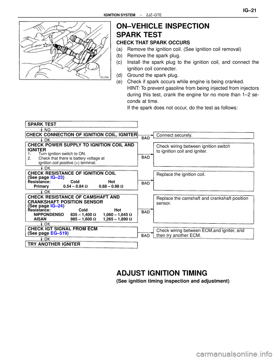
CHECK THAT SPARK OCCURS
(a) Remove the ignition coil. (See ignition coil removal)
(b) Remove the spark plug.
(c) Install the spark plug to the ignition coil, and connect the
ignition coil connecter.
(d) Ground the spark plug.
(e) Check if spark occurs while engine is being cranked.
HINT: To prevent gasoline from being injected from injectors
during this test, crank the engine for no more than 1±2 se-
conds at time.
If the spark does not occur, do the test as follows:
SPARK TEST
CHECK CONNECTION OF IGNITION COIL, IGNITER
CHECK POWER SUPPLY TO IGNITION COIL AND
IGNITER
1. Turn ignition switch to ON.
2. Check that there is battery voltage at
ignition coil positive (+) terminal.
CHECK RESISTANCE OF IGNITION COIL(See page IG±23)Resistance: Cold Hot
Primary 0.54 ± 0.84 �0.68 ± 0.98 �
CHECK RESISTANCE OF CAMSHAFT AND
CRANKSHAFT POSITION SENSOR
(See page IG±24)Resistance: Cold Hot
NIPPONDENSO 835 ± 1,400 �1,060 ± 1,645 �
AISAN 985 ± 1,600 �1,265 ± 1,890 �
CHECK IGT SIGNAL FROM ECM(See page EG±519)
TRY ANOTHER IGNITER
Connect securely.
Check wiring between ignition switch
to ignition coil and igniter.
Replace the ignition coil.
Replace the camshaft and crankshaft position
sensor.
Check wiring between ECM,and igniter, and
then try another ECM.
ADJUST IGNITION TIMING
(See ignition timing inspection and adjustment)
± IGNITION SYSTEM2JZ±GTEIG±21
Page 1159 of 2543
CAMSHAFT POSITION SENSORS
INSPECTION
NOTICE: ºColdº and ºHotº in the following sentences express
the temperature of the sensors themselves. ºColdº is from
±105C (145F) to 505C (1225F) and ºHotº is from 505C (1225F) to
1005C (2125F).
1. DISCONNECT CAMSHAFT POSITION SENSOR
CONNECTORS
2. INSPECT CAMSHAFT POSITION SENSOR RESISTANCE
Using an ohmmeter, measure the resistance between termi-
nals.
Resistance:
Cold
NIPPONDENSO
835±1,400 �
AISAN
985±1,600 �
Hot
NIPPONDENSO
1,060±1,645 �
AISAN
1,265±1,890 �
If the resistance is not as specified, replace the camshaft
position sensor.
3. RECONNECT CAMSHAFT POSITION SENSOR
CONNECTORS IG±24
± IGNITION SYSTEM(2JZ±GTE)
Page 1160 of 2543
CRANKSHAFT POSITION SENSOR
INSPECTION
NOTICE: ºColdº and ºHotº in the following sentences express
the temperature of the sensors themselves. ºColdº is from
±105C (145F) to 505C (1225F) and ºHotº is from 505C (1225F) to
1005C (2125F).
1. REMOVE NO.2 AIR TUBE FOR CAC
2. DISCONNECT CRANKSHAFT POSITION SENSOR
CONNECTOR
3. INSPECT CRANKSHAFT POSITION SENSOR
RESISTANCE
Using an ohmmeter, measure the resistance between termi-
nals.
Resistance:
Cold
NIPPONDENSO
835±1,400 �
AISAN
985±1,600 �
Hot
NIPPONDENSO
1,060±1,645 �
AISAN
1,265±1,890 �
If the resistance is not as specified, replace the crankshaft
position sensor.
4. RECONNECT CRANKSHAFT POSITION SENSOR
CONNECTOR
5. REINSTALL NO.2 AIR TUBE FOR CAC
IGNITER INSPECTION
(See procedure Spark Test on page IG±22)
± IGNITION SYSTEM(2JZ±GTE)IG±25
Page 1163 of 2543
CAMSHAFT POSITION SENSOR
COMPONENTS FOR REMOVAL AND
INSTALLATION
CAMSHAFT POSITION SENSOR
REMOVAL
Installation is in the reverse order of removal.
1. DISCONNECT IAC VALVE CONNECTOR
2. DISCONNECT AIR HOSE FROM IAC VALVE
3. REMOVE ENGINE HANGER
Remove the 2 bolts, ground strap and engine hanger.
Torque: 39 NVm (400 kgfVcm, 29 ftVlbf)
4. DISCONNECT CAMSHAFT POSITION SENSOR
CONNECTORS
5. REMOVE CAMSHAFT POSITION SENSORS
Remove the 4 bolts, 2 camshaft position sensors and 2 gas-
kets.
Torque: 6.4 NVm (65 kgfVcm, 56 in.Vlbf)
IG±28± IGNITION SYSTEM2JZ±GTE
Page 1164 of 2543
CRANKSHAFT POSITION SENSOR
COMPONENTS FOR REMOVAL AND
INSTALLATION
± IGNITION SYSTEM2JZ±GTEIG±29
Page 1165 of 2543
CRANKSHAFT POSITION SENSOR
REMOVAL
Installation is in the reverse order of removal.
1. REMOVE GENERATOR
(See generator removal in Charging System)
2. DISCONNECT CRANKSHAFT POSITION SENSOR
CONNECTOR
(a) Disconnect the sensor connector from the bracket.
(b) Disconnect the sensor connector from the wiring connector.
3. REMOVE CRANKSHAFT POSITION SENSOR
(a) Disconnect the wire clamp from the cylinder block.
(b) Remove the bolt and crankshaft position sensor.
Torque: 8.8 NVm (90 kgfVcm, 78 in.Vlbf)
IG±30± IGNITION SYSTEM(2JZ±GTE)
Page 1166 of 2543

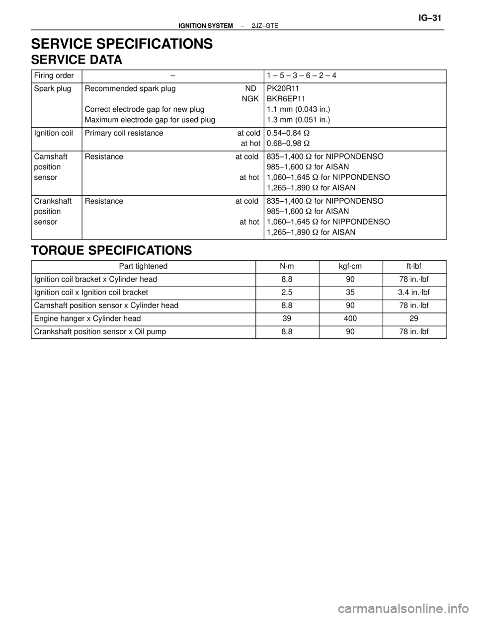
SERVICE SPECIFICATIONS
SERVICE DATA
����� �����Firing order����������������� �����������������±���������������� ����������������1 ± 5 ± 3 ± 6 ± 2 ± 4����� �
���� �
���� �
���� �����
Spark plug����������������� �
���������������� �
���������������� �
���������������� �����������������
Recommended spark plug ND
NGK
Correct electrode gap for new plug
Maximum electrode gap for used plug���������������� �
��������������� �
��������������� �
��������������� ����������������
PK20R11
BKR6EP11
1.1 mm (0.043 in.)
1.3 mm (0.051 in.)
����� �
���� �����
Ignition coil����������������� �
���������������� �����������������
Primary coil resistance at cold
at hot���������������� �
��������������� ����������������
0.54±0.84 �
0.68±0.98 �
����� �
���� �
���� �
���� �����
Camshaft
position
sensor����������������� �
���������������� �
���������������� �
���������������� �����������������
Resistance at cold
at hot���������������� �
��������������� �
��������������� �
��������������� ����������������
835±1,400 � for NIPPONDENSO
985±1,600 � for AISAN
1,060±1,645 � for NIPPONDENSO
1,265±1,890 � for AISAN
����� �
���� �
���� �
���� �����
Crankshaft
position
sensor����������������� �
���������������� �
���������������� �
���������������� �����������������
Resistance at cold
at hot���������������� �
��������������� �
��������������� �
��������������� ����������������
835±1,400 � for NIPPONDENSO
985±1,600 � for AISAN
1,060±1,645 � for NIPPONDENSO
1,265±1,890 � for AISAN
TORQUE SPECIFICATIONS
�������������������� ��������������������Part tightened������ ������NVm������ ������kgfVcm������� �������ftVlbf�������������������� ��������������������Ignition coil bracket x Cylinder head������ ������8.8������ ������90������� �������78 in.Vlbf�������������������� �
������������������� ��������������������Ignition coil x Ignition coil bracket������ �
����� ������2.5������ �
����� ������35������� �
������ �������3.4 in.Vlbf
�������������������� ��������������������Camshaft position sensor x Cylinder head������ ������8.8������ ������90������� �������78 in.Vlbf
�������������������� ��������������������Engine hanger x Cylinder head������ ������39������ ������400������� �������29
�������������������� ��������������������Crankshaft position sensor x Oil pump������ ������8.8������ ������90������� �������78 in.Vlbf
± IGNITION SYSTEM2JZ±GTEIG±31