Page 490 of 2543
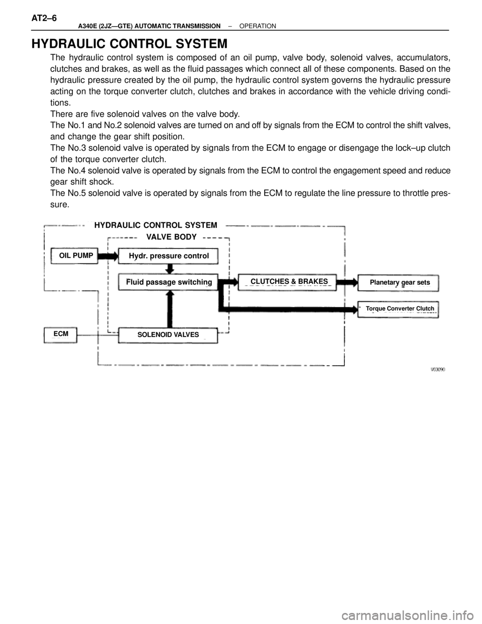
HYDRAULIC CONTROL SYSTEM
The hydraulic control system is composed of an oil pump, valve body, solenoid valves, accumulators,
clutches and brakes, as well as the fluid passages which connect all of these components. Based on the
hydraulic pressure created by the oil pump, the hydraulic control system governs the hydraulic pressure
acting on the torque converter clutch, clutches and brakes in accordance with the vehicle driving condi-
tions.
There are five solenoid valves on the valve body.
The No.1 and No.2 solenoid valves are turned on and off by signals from the ECM to control the shift valves,
and change the gear shift position.
The No.3 solenoid valve is operated by signals from the ECM to engage or disengage the lock±up clutch
of the torque converter clutch.
The No.4 solenoid valve is operated by signals from the ECM to control the engagement speed and reduce
gear shift shock.
The No.5 solenoid valve is operated by signals from the ECM to regulate the line pressure to throttle pres-
sure.
HYDRAULIC CONTROL SYSTEM
VALVE BODY
OIL PUMP
ECMSOLENOID VALVES
CLUTCHES & BRAKES
Hydr. pressure control
Fluid passage switchingPlanetary gear sets
Torque Converter Clutch
AT2±6± A340E (2JZÐGTE) AUTOMATIC TRANSMISSIONOPERATION
Page 491 of 2543
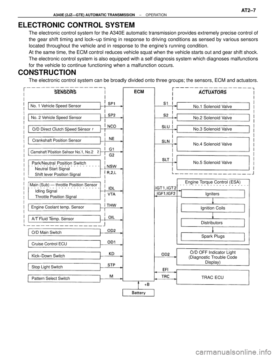
ELECTRONIC CONTROL SYSTEM
The electronic control system for the A340E automatic transmission provides extremely precise control of
the gear shift timing and lock±up timing in response to driving conditions as sensed by various sensors
located throughout the vehicle and in response to the engine's running condition.
At the same time, the ECM control reduces vehicle squat when the vehicle starts out and gear shift shock.
The electronic control system is also equipped with a self diagnosis system which diagnoses malfunctions
for the vehicle to continue functioning when a malfunction occurs.
CONSTRUCTION
The electronic control system can be broadly divided onto three groups; the sensors, ECM and actuators.
No. 1 Vehicle Speed Sensor
No. 2 Vehicle Speed Sensor
Crankshaft Position Sensor
Camshaft Position Sensor No.1, No.2
Park/Neutral Position Switch
� Neutral Start Signal
� Shift lever Position Signal
� Idling Signal
� Throttle Position Signal
Main (Sub) Ð throttle Position Sensor
Engine Coolant temp. Sensor
A/T Fluid Temp. Sensor
O/D Main Switch
Cruise Control ECU
Kick±Down Switch
Stop Light Switch
Pattern Select Switch
SENSORSECMACTUATORS
No.1 Solenoid Valve
No.2 Solenoid Valve
No.3 Solenoid Valve
No.4 Solenoid Valve
No.5 Solenoid Valve
Engine Torque Control (ESA)
Igniters
Ignition Coils
Distributors
Spark Plugs
O/D OFF Indicator Light
(Diagnostic Trouble Code
Display)
TRAC ECU
O/D Direct Clutch Speed Sensor
± A340E (2JZÐGTE) AUTOMATIC TRANSMISSIONOPERATIONAT2±7
Page 497 of 2543
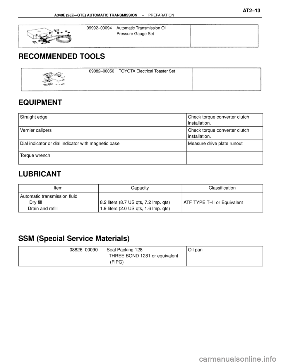
09992±00094 Automatic Transmission Oil
Pressure Gauge Set
09082±00050 TOYOTA Electrical Toaster Set
RECOMMENDED TOOLS
EQUIPMENT
������������������������� �������������������������Straight edge������������ ������������Check torque converter clutch
installation.
������������������������� �������������������������
Vernier calipersCheck torque converter clutch������������������������� �������������������������Vernier cali ersCheck torque converter clutch
installation.������������������������� �
������������������������ �������������������������Dial indicator or dial indicator with magnetic baseMeasure drive plate runout
�������������������������������������������������� �
������������������������ �������������������������
Torque wrench
LUBRICANT
������������ ������������Item������������� �������������Capacity������������� �������������Classification
������������ ������������Automatic transmission fluid
Dry fill8 2 liters (8 7 US qts 7 2 lmpqts)ATF TYPE T II or Equivalent������������ �
����������� ������������
Dry fill
Drain and refill
8.2 liters (8.7 US qts, 7.2 lmp. qts)
1.9 liters (2.0 US qts, 1.6 lmp. qts)
ATF TYPE T±II or Equivalent
SSM (Special Service Materials)
������������������������� �
������������������������ �
������������������������ �������������������������
08826±00090 Seal Packing 128
THREE BOND 1281 or equivalent
(FIPG)������������ �
����������� �
����������� ������������
Oil pan
± A340E (2JZÐGTE) AUTOMATIC TRANSMISSIONPREPARATIONAT2±13
Page 499 of 2543
(b) Install the output flange and 2 washers.
(c) Install and torque a new nut.
Torque: 123 NVm (1.250 kgfVcm, 90 ftVlbf)
HINT: Shift the shift lever to the P position
(d) Using a hammer and chisel, stake the nut.
8. INSTALL PROPELLER SHAFT
(See page PR±13)
9. INSTALL FRONT EXHAUST PIPE AND HEAT INSULATOR
(See page AT2±22)
10. FILL AND CHECK A/T FLUID (See page AT2±42)
A/T FLUID TEMP. SENSOR
REPLACEMENT
1. DISCONNECT A/T FLUID TEMP. SENSOR CONNECTOR
2. REMOVE A/T FLUID TEMP. SENSOR
(a) Remove the A/T fluid temp. sensor.
(b) Remove the O±ring from it.
3. INSTALL A/T FLUID TEMP. SENSOR
(a) Coat a new O±ring with A/T fluid and install it to the A/T fluid
temp. sensor
(b) Install the A/T fluid temp. sensor.
Torque: 15 NVm (150 kgfVcm, 11 ftVlbf)
4. CONNECT A/T FLUID TEMP. SENSOR CONNECTOR
± A340E (2JZÐGTE) AUTOMATIC TRANSMISSIONON±VEHICLE REPAIRAT2±15
Page 500 of 2543
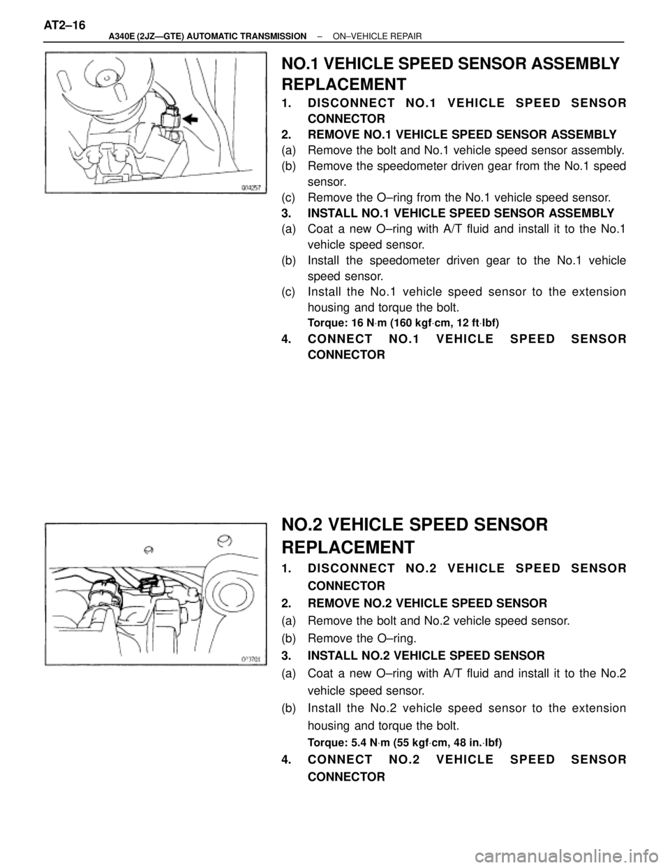
NO.1 VEHICLE SPEED SENSOR ASSEMBLY
REPLACEMENT
1. DISCONNECT NO.1 VEHICLE SPEED SENSOR
CONNECTOR
2. REMOVE NO.1 VEHICLE SPEED SENSOR ASSEMBLY
(a) Remove the bolt and No.1 vehicle speed sensor assembly.
(b) Remove the speedometer driven gear from the No.1 speed
sensor.
(c) Remove the O±ring from the No.1 vehicle speed sensor.
3. INSTALL NO.1 VEHICLE SPEED SENSOR ASSEMBLY
(a) Coat a new O±ring with A/T fluid and install it to the No.1
vehicle speed sensor.
(b) Install the speedometer driven gear to the No.1 vehicle
speed sensor.
(c) Install the No.1 vehicle speed sensor to the extension
housing and torque the bolt.
Torque: 16 NVm (160 kgfVcm, 12 ftVlbf)
4. CONNECT NO.1 VEHICLE SPEED SENSOR
CONNECTOR
NO.2 VEHICLE SPEED SENSOR
REPLACEMENT
1. DISCONNECT NO.2 VEHICLE SPEED SENSOR
CONNECTOR
2. REMOVE NO.2 VEHICLE SPEED SENSOR
(a) Remove the bolt and No.2 vehicle speed sensor.
(b) Remove the O±ring.
3. INSTALL NO.2 VEHICLE SPEED SENSOR
(a) Coat a new O±ring with A/T fluid and install it to the No.2
vehicle speed sensor.
(b) Install the No.2 vehicle speed sensor to the extension
housing and torque the bolt.
Torque: 5.4 NVm (55 kgfVcm, 48 in.Vlbf)
4. CONNECT NO.2 VEHICLE SPEED SENSOR
CONNECTOR AT2±16
± A340E (2JZÐGTE) AUTOMATIC TRANSMISSIONON±VEHICLE REPAIR
Page 501 of 2543
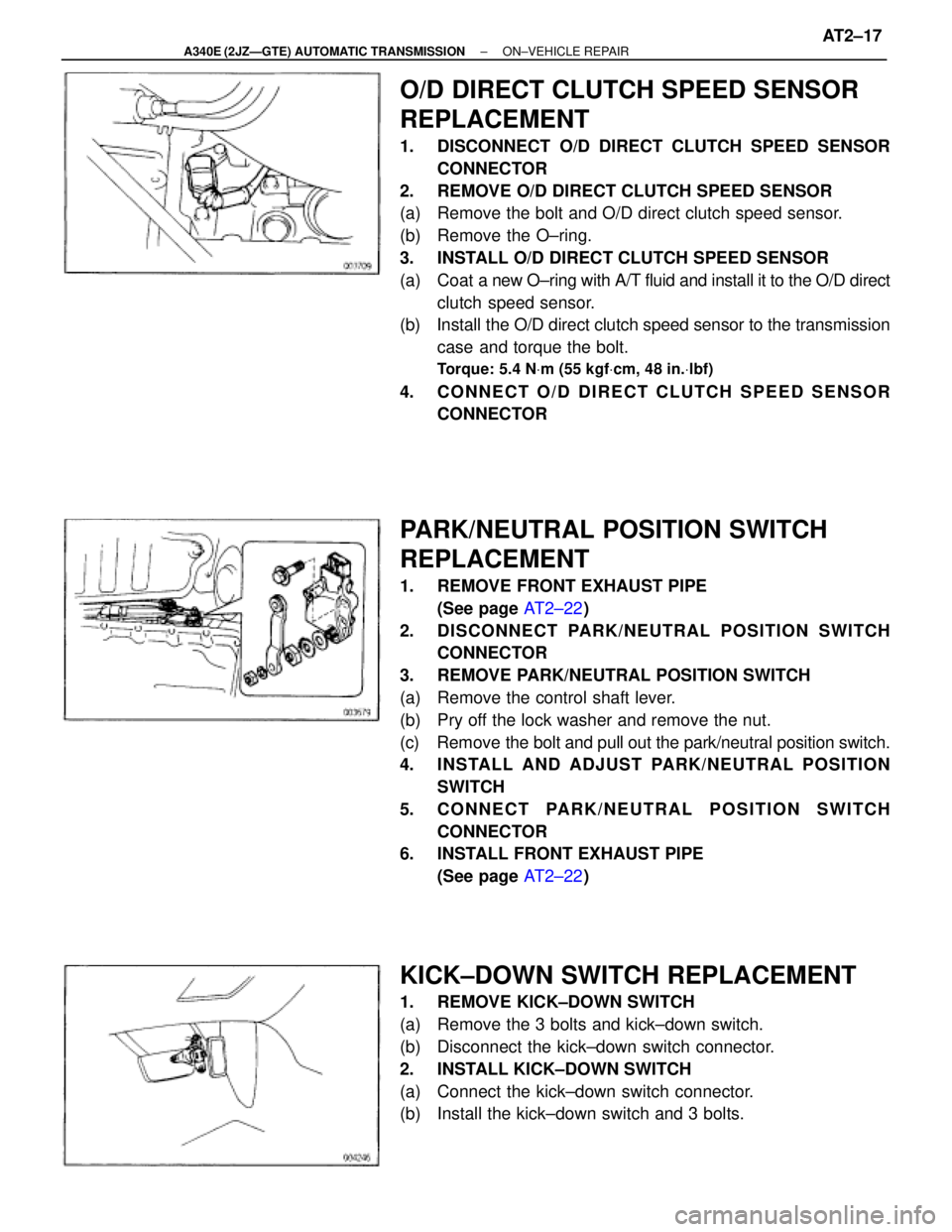
O/D DIRECT CLUTCH SPEED SENSOR
REPLACEMENT
1. DISCONNECT O/D DIRECT CLUTCH SPEED SENSOR
CONNECTOR
2. REMOVE O/D DIRECT CLUTCH SPEED SENSOR
(a) Remove the bolt and O/D direct clutch speed sensor.
(b) Remove the O±ring.
3. INSTALL O/D DIRECT CLUTCH SPEED SENSOR
(a) Coat a new O±ring with A/T fluid and install it to the O/D direct
clutch speed sensor.
(b) Install the O/D direct clutch speed sensor to the transmission
case and torque the bolt.
Torque: 5.4 NVm (55 kgfVcm, 48 in.Vlbf)
4. CONNECT O/D DIRECT CLUTCH SPEED SENSOR
CONNECTOR
PARK/NEUTRAL POSITION SWITCH
REPLACEMENT
1. REMOVE FRONT EXHAUST PIPE
(See page AT2±22)
2. DISCONNECT PARK/NEUTRAL POSITION SWITCH
CONNECTOR
3. REMOVE PARK/NEUTRAL POSITION SWITCH
(a) Remove the control shaft lever.
(b) Pry off the lock washer and remove the nut.
(c) Remove the bolt and pull out the park/neutral position switch.
4. INSTALL AND ADJUST PARK/NEUTRAL POSITION
SWITCH
5. CONNECT PARK/NEUTRAL POSITION SWITCH
CONNECTOR
6. INSTALL FRONT EXHAUST PIPE
(See page AT2±22)
KICK±DOWN SWITCH REPLACEMENT
1. REMOVE KICK±DOWN SWITCH
(a) Remove the 3 bolts and kick±down switch.
(b) Disconnect the kick±down switch connector.
2. INSTALL KICK±DOWN SWITCH
(a) Connect the kick±down switch connector.
(b) Install the kick±down switch and 3 bolts.
± A340E (2JZÐGTE) AUTOMATIC TRANSMISSIONON±VEHICLE REPAIRAT2±17
Page 502 of 2543
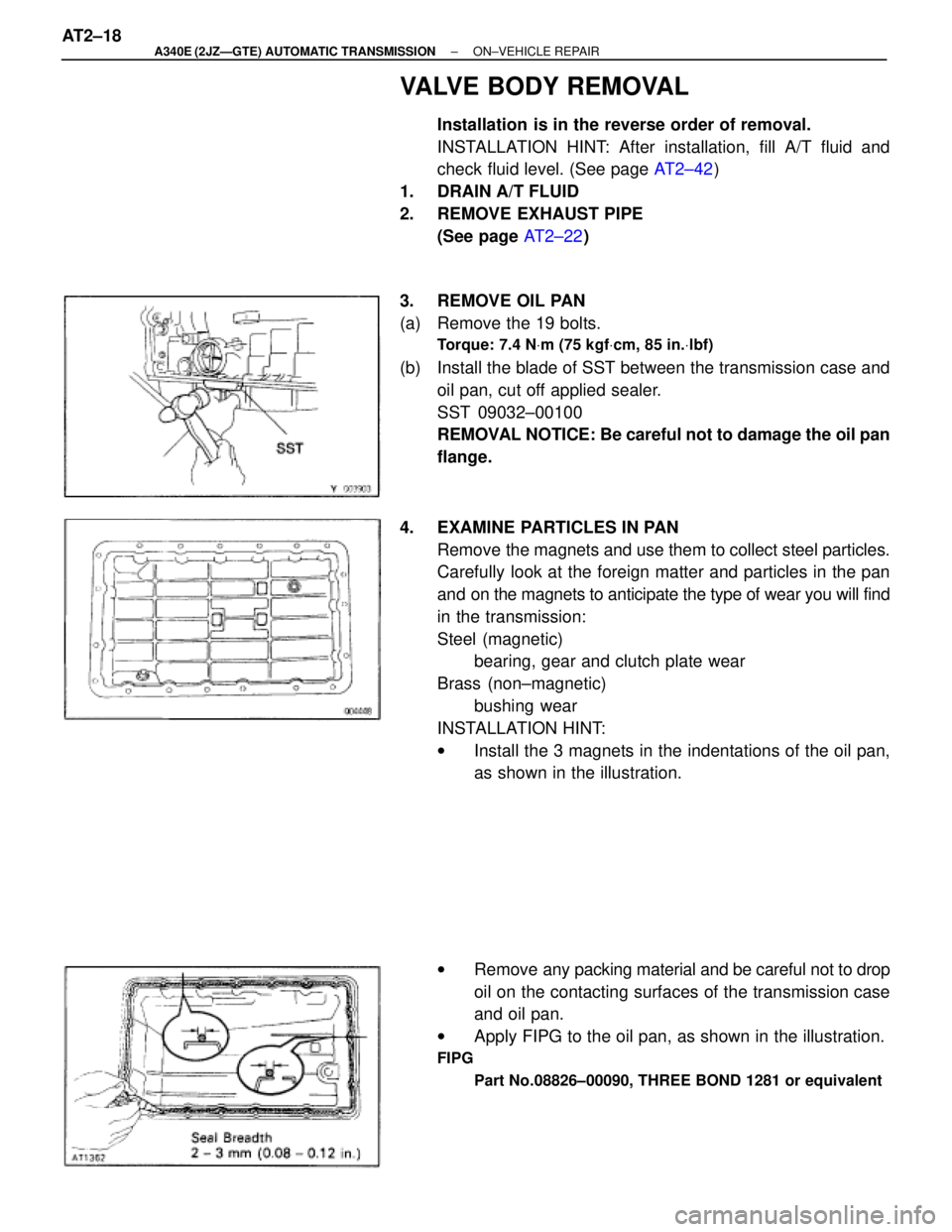
VALVE BODY REMOVAL
Installation is in the reverse order of removal.
INSTALLATION HINT: After installation, fill A/T fluid and
check fluid level. (See page AT2±42)
1. DRAIN A/T FLUID
2. REMOVE EXHAUST PIPE
(See page AT2±22)
3. REMOVE OIL PAN
(a) Remove the 19 bolts.
Torque: 7.4 NVm (75 kgfVcm, 85 in.Vlbf)
(b) Install the blade of SST between the transmission case and
oil pan, cut off applied sealer.
SST 09032±00100
REMOVAL NOTICE: Be careful not to damage the oil pan
flange.
4. EXAMINE PARTICLES IN PAN
Remove the magnets and use them to collect steel particles.
Carefully look at the foreign matter and particles in the pan
and on the magnets to anticipate the type of wear you will find
in the transmission:
Steel (magnetic)
bearing, gear and clutch plate wear
Brass (non±magnetic)
bushing wear
INSTALLATION HINT:
wInstall the 3 magnets in the indentations of the oil pan,
as shown in the illustration.
wRemove any packing material and be careful not to drop
oil on the contacting surfaces of the transmission case
and oil pan.
wApply FIPG to the oil pan, as shown in the illustration.
FIPG
Part No.08826±00090, THREE BOND 1281 or equivalent
AT2±18± A340E (2JZÐGTE) AUTOMATIC TRANSMISSIONON±VEHICLE REPAIR
Page 503 of 2543
5. REMOVAL OIL STRAINER
Remove the 3 bolts holding the oil strainer to the valve body.
Torque: 10 NVm (100 kgfVcm, 7 ftVlbf)
6. REMOVE SOLENOID WIRING
(a) Remove the 2 bolts and clamp.
(b) Disconnect the 5 connectors from the solenoid valves.
7. REMOVE VALVE BODY
(a) Remove the 20 bolts.
Torque: 10 NVm (100 kgfVcm, 7 ftVlbf)
INSTALLATION HINT: Each bolt length is indicated in the il-
lustration.
(b) Remove the valve body.
INSTALLATION HINT: Align the groove of the manual valve
to the pin of the lever.
± A340E (2JZÐGTE) AUTOMATIC TRANSMISSIONON±VEHICLE REPAIRAT2±19