Page 1166 of 2248

B6M0383A
1. CHECK MAIN POWER SUPPLY FOR STARTER
MOTOR.
Measure voltage between starter motor terminal B and
body.
Connector & terminal / Specified voltage:
Terminal B—Body / 10 V, or more
B6M0384A
2. CHECK POWER SUPPLY FOR MAGNET COIL OF
STARTER MOTOR.
1) Disconnect all connectors from starter motor.
2) Turn ignition switch to ST (START).
3) Depress clutch pedal.
4) Measure voltage between starter motor terminal S con-
nector and body.
Connector & terminal / Specified voltage:
(B14) Terminal S—Body / 10 V, or more
B6M0385A
3. CHECK POWER SUPPLY FOR STARTER
INTERLOCK RELAY.
1) Disconnect all connectors from starter motor.
2) Disconnect connector of starter interlock relay.
3) Turn ignition switch to ST (START).
4) Measure voltage between starter interlock relay con-
nector and body.
Connector & terminal / Specified voltage:
(B105) No. 2—Body / 10 V, or more
(B105) No. 4—Body / 10 V, or more
B6M0386A
4. CHECK STARTER INTERLOCK RELAY.
1) Disconnect connector of starter interlock relay.
2) Connect battery to terminal No. 2 and ground terminal
No. 1.
3) Check continuity between terminals as indicated in
table below:
When current flows. Between terminals
No. 3 and No. 4Continuity exists.
When current does not flow. Between terminals
No. 3 and No. 4Continuity does not
exist.
Between terminals
No. 1 and No. 2Continuity exists.
62
6-2DIAGNOSTICS
1. Starter Interlock System (MT Model)
Page 1169 of 2248
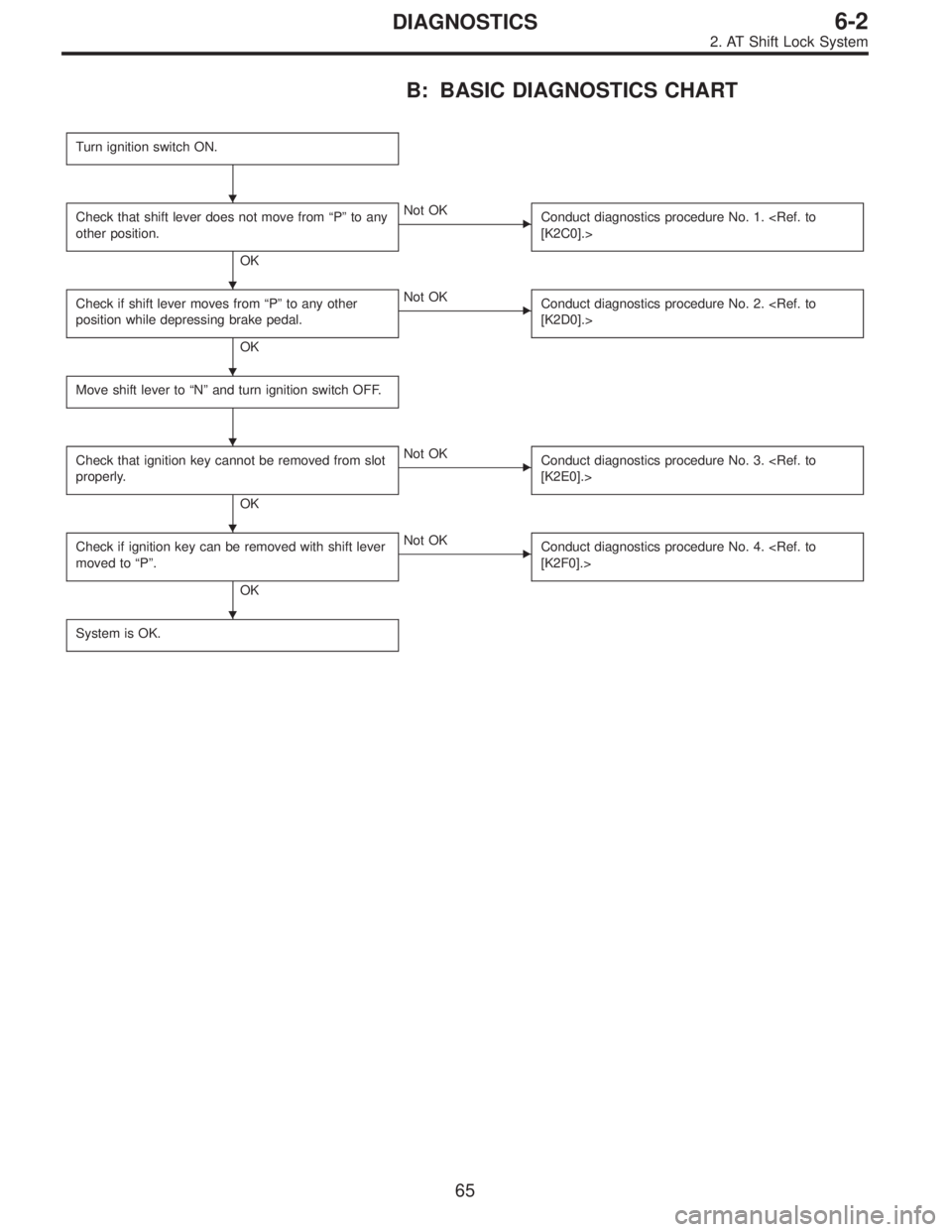
B: BASIC DIAGNOSTICS CHART
Turn ignition switch ON.
Check that shift lever does not move from“P”to any
other position.
OK
�Not OK
Conduct diagnostics procedure No. 1.
[K2C0].>
Check if shift lever moves from“P”to any other
position while depressing brake pedal.
OK
�Not OK
Conduct diagnostics procedure No. 2.
[K2D0].>
Move shift lever to“N”and turn ignition switch OFF.
Check that ignition key cannot be removed from slot
properly.
OK
�Not OK
Conduct diagnostics procedure No. 3.
[K2E0].>
Check if ignition key can be removed with shift lever
moved to“P”.
OK
�Not OK
Conduct diagnostics procedure No. 4.
[K2F0].>
System is OK.
�
�
�
�
�
�
65
6-2DIAGNOSTICS
2. AT Shift Lock System
Page 1171 of 2248

Check if stop light comes on when brake pedal is
depressed.
OK
�Not OK
Check stop light system.
Check if voltage between shift lock contro")
D: DIAGNOSTICS PROCEDURE No. 2 (SHIFT
LOCK DOES NOT RELEASE.)
Check if stop light comes on when brake pedal is
depressed.
OK
�Not OK
Check stop light system.
Check if voltage between shift lock control module
terminal No. 4 and body is at least 10 V when brake
pedal is depressed.
OK
�Not OK
Repair or replace wiring harness or faulty connector
between stop light switch and shift lock control
module.
Check if voltage between shift lock control module
terminal No. 1 and body is at least 10 V when
ignition switch is turned ON.
OK
�Not OK
Check fuse.
Repair or replace wiring harness or faulty connector
between ignition switch and shift lock control
module.
Turn ignition switch OFF.
Disconnect connector from shift lock control module.
Check if continuity exists between terminal No. 2 of
shift lock control module connector and body when
shift lever is set at“P”.
OK
�Not OK
Check inhibitor switch or repair wiring harness.
Check if continuity exists between terminal No. 5 of
shift lock control module connector and body when
shift lever is set at“P”.
OK
�Not OK
Check“P”position switch or repair wiring harness.
Measure resistance between terminal No. 1 of shift
lock control module connector and body.
Resistance is less than 20Ω.
OK
�Not OK
Shift lock solenoid circuit is shorted. Repair or
replace wiring harness or faulty connector between
shift lock solenoid and shift lock control module.
Resistance is at least 10Ω.
OK
�Not OK
Shift lock solenoid is shorted or poorly grounded.
* After repairs, recheck solenoid operation.
If still faulty, replace shift lock control module.
Check if resistance between terminal No. 10 of shift
lock control module connector and body is less than
10Ω.
OK
�Not OK
Shift lock control module ground circuit open or poor
connector contact.
Replace shift lock control module.
�
�
�
�
�
�
�
�
�
�
67
6-2DIAGNOSTICS
2. AT Shift Lock System
Page 1172 of 2248

Check if shift lock operates properly.
OK
�Not OK
Check diagnostics procedure“No. 1”or“No. 2”.
Check if voltage between shift l")
E: DIAGNOSTICS PROCEDURE No. 3 (KEY
INTERLOCK DOES NOT OPERATE.)
Check if shift lock operates properly.
OK
�Not OK
Check diagnostics procedure“No. 1”or“No. 2”.
Check if voltage between shift lock control module
terminal No. 8 and body is at least 10 V when
ignition key is inserted in its slot.
OK
�Not OK
Faulty key switch.
Repair or replace wiring harness or faulty connector
between fuse box and shift lock control module.
Check if voltage between shift lock control module
terminal No. 7 and body is at least 10 V when
ignition switch is set to ACC.
OK
�Not OK
Repair or replace wiring harness or faulty connector
between ignition switch and shift lock control
module.
Disconnect connector from shift lock control module.
Check if resistance between terminal No. 9 and
terminal No. 11 of shift lock control module
connector is less than 8Ω.
OK
�Not OK
Key lock solenoid circuit open. Repair or replace
wiring harness or faulty connector between key lock
solenoid and shift lock control module.
Voltage is at least 4 V. (*)
OK
�Not OK
Key lock solenoid is shorted.
Repair or replace wiring harness or faulty connector
between key lock solenoid and shift lock control
module.
* After repairs, recheck for proper operation.
If still faulty, replace shift lock control module.
Check if resistance between terminal No. 11 of shift
lock control module connector and body is at least 1
MΩ.
OK
�Not OK
Replace shift lock control module.
*: When conducting operational checks of the key lock solenoid, do not apply 12 V to solenoid for more than one second, since
this may break solenoid circuit.
�
�
�
�
�
�
68
6-2DIAGNOSTICS
2. AT Shift Lock System
Page 1173 of 2248

Check if shift lock operates properly.
OK
�Not OK
Check diagnostics procedure“No. 1”or“No. 2”.
Check if voltage between shift l")
F: DIAGNOSTICS PROCEDURE No. 4 (KEY
INTERLOCK DOES NOT RELEASE.)
Check if shift lock operates properly.
OK
�Not OK
Check diagnostics procedure“No. 1”or“No. 2”.
Check if voltage between shift lock control module
terminal No. 8 and body is at least 10 V when
ignition key is inserted in its slot.
OK
�Not OK
Faulty key switch. Repair or replace wiring harness
or faulty connector between fuse box and shift lock
control module.
Check if voltage between shift lock control module
terminal No. 7 and body is at least 10 V when
ignition switch is set to ACC.
OK
�Not OK
Repair or replace wiring harness or faulty connector
between ignition switch and shift lock control
module.
Disconnect connector from shift lock control module.
Check if resistance between terminal No. 9 and
terminal No. 11 of shift lock control module
connector is less than 8Ω. (*)
OK
�Not OK
Key lock solenoid circuit open.
Repair or replace wiring harness or faulty connector
between key lock solenoid and shift lock control
module.
Voltage is at least 4 V.
OK
�Not OK
Key lock solenoid is shorted.
Repair or replace wiring harness or faulty connector
between key lock solenoid and shift lock control
module.
* After repairs, recheck for proper operation.
If still faulty, replace shift lock control module.
Check if resistance between terminal No. 9 of shift
lock control module connector and body is at least 1
MΩ.
OK
�Not OK
Repair or replace wiring harness or faulty connector
between key lock solenoid and shift lock control
module.
* After repairs, recheck for proper operation.
If still faulty, replace shift lock control module.
Replace shift lock control module.
*: When conducting operational checks of the key lock solenoid, do not apply 12 V to solenoid for more than one second, since
this may break solenoid circuit.
�
�
�
�
�
�
69
6-2DIAGNOSTICS
2. AT Shift Lock System
Page 1175 of 2248
 Remove combination meter.
2) Turn ignition switch to ON.
3) Measure voltage at combination meter connector termi-
nal.
Connector & terminal / S")
B6M0530A
1. CHECK POWER SUPPLY FOR COMBINATION
METER.
1) Remove combination meter.
2) Turn ignition switch to ON.
3) Measure voltage at combination meter connector termi-
nal.
Connector & terminal / Specified voltage:
(i14) No. 11—Body / 10 V, or more
B6M0252B
2. CHECK GROUND CIRCUIT OF COMBINATION
METER.
1) Turn ignition switch to OFF.
2) Measure resistance of harness connector between
combination meter and body.
Connector & terminal / Specified voltage:
(i12) No. 1—Body / 10Ω, max.
B6M0294B
3. CHECK HARNESS CONNECTOR BETWEEN
COMBINATION METER AND VEHICLE SPEED
SENSOR 2.
1) Disconnect connector from vehicle speed sensor 2.
2) Measure resistance of harness connector between
vehicle speed sensor 2 and combination meter.
Connector & terminal / Specified resistance:
(B17) No. 1—(i11)No.2/10Ω, max.
(B17) No. 2—(i11)No.3/10Ω, max.
4. CHECK VEHICLE SPEED SENSOR 2.
NOTE:
�If resistance between terminals of vehicle speed sensor
2 is out of specification, the sensor may have a failure.
�If resistance is OK and voltage between terminals of
vehicle speed sensor 2 is out of specification, mechanical
trouble may be present between vehicle speed sensor 2
and speedometer shaft in transmission.
71
6-2DIAGNOSTICS
3. Combination Meter
Page 1176 of 2248
B3M0289
1) Disconnect connector from vehicle speed sensor 2.
2) Measure resistance between terminals of vehicle speed
sensor 2.
Terminals / Specified resistance:
No. 1—No. 2 / 350—450Ω
B3M0256
WARNING:
Be careful not to be caught up by the running wheels.
3) Set the vehicle on free roller, or lift-up the vehicle and
support with safety stands.
4) Drive the vehicle at speed greater than 20 km/h (12
MPH).
5) Measure voltage between terminals of vehicle speed
sensor 2.
Terminals / Specified voltage:
No. 1—No.2/5V,min. (AC range)
B3M0257
�Using an oscilloscope:
(1) Turn ignition switch to OFF.
(2) Set oscilloscope to vehicle speed sensor 2.
(3) Drive the vehicle at speed greater than 20 km/h (12
MPH).
(4) Measure signal voltage.
Specified voltage (V): 5 V, min.
B3M0254A
72
6-2DIAGNOSTICS
3. Combination Meter
Page 1177 of 2248

4. Power Window
A: DIAGNOSTICS PROCEDURE-1
Trouble symptom A: All door windows do not operate.
1. Check fuse and power supply.
OK
�Not OK
�Replace fuse or circuit breaker.
�Repair or replace wiring harness.
2. Check power window relay.
OK
�Not OK
Replace power window relay.
3. Check ground circuit of power window relay.
OK
�Not OK
Repair or replace wiring harness.
4. Check harness connector between power
window relay and power window main switch
(driver’s door switch).
OK
�Not OK
Repair or replace wiring harness.
5. Check power window main switch.
OK
�Not OK
Replace power window main switch.
6. Check ground circuit of power window main
switch.
OK
�Not OK
Repair or replace wiring harness.
System is OK.
B6M0390A
1. CHECK FUSE AND POWER SUPPLY.
1) Check fuse No. 15.
2) Disconnect connector of power window relay.
3) Turn ignition switch to ON.
4) Measure voltage between power window relay connec-
tor and body.
Connector & terminal / Specified voltage:
(B42) No. 1—Body / 10 V, or more
(B42) No. 2—Body / 10 V, or more
�
�
�
�
�
�
73
6-2DIAGNOSTICS
4. Power Window
 Disconnect connector from vehicle speed sensor 2.
2) Measure resistance between terminals of vehicle speed
sensor 2.
Terminals / Specified resistance:
No. 1—No. 2 / 350—450Ω
B3M0256
W")