Page 1270 of 2248
G3M0151
5. FINISHING DIAGNOSIS OPERATION
1) Disconnect test mode connector at the lower portion of
instrument panel (on the driver’s side), to the side of the
center console box.
2) Turn Subaru select monitor switch and ignition switch to
OFF.
3) Disconnect Subaru select monitor from its data link con-
nector.
64
2-7ON-BOARD DIAGNOSTICS II SYSTEM
3. Diagnosis System
Page 1271 of 2248
, main relay and fuel pump relay.
CAUTION:
�All Airbag system wirin")
4. Cautions
A: SUPPLEMENTAL RESTRAINT SYSTEM
“AIRBAG”
Airbag system wiring harness is routed near the engine
control module (ECM), main relay and fuel pump relay.
CAUTION:
�All Airbag system wiring harness and connectors
are colored yellow. Do not use electrical test equip-
ment on these circuit.
�Be careful not to damage Airbag system wiring har-
ness when servicing the engine control module (ECM),
transmission control module (TCM), main relay and
fuel pump relay.
B: PRECAUTIONS
1) Never connect the battery in reverse polarity.
�The ECM will be destroyed instantly.
�The fuel injector and other part will be damaged in just
a few minutes more.
2) Do not disconnect the battery terminals while the
engine is running.
�A large counter electromotive force will be generated in
the alternator, and this voltage may damage electronic
parts such as ECM, etc.
3) Before disconnecting the connectors of each sensor
and the ECM, be sure to turn OFF the ignition switch.
4) Before removing ECM from the located position, dis-
connect two cables on battery.
�Otherwise, the ECM may be damaged.
5) The connectors to each sensor in the engine compart-
ment and the harness connectors on the engine side and
body side are all designed to be waterproof. However, it is
still necessary to take care not to allow water to get into the
connectors when washing the vehicle, or when servicing
the vehicle on a rainy day.
6) Every MFI-related part is a precision part. Do not drop
them.
7) Observe the following cautions when installing a radio
in MFI equipped models.
CAUTION:
�The antenna must be kept as far apart as possible
from the control unit.
(The ECM is located under the steering column, inside
of the instrument panel lower trim panel.)
�The antenna feeder must be placed as far apart as
possible from the ECM and MFI harness.
�Carefully adjust the antenna for correct matching.
65
2-7ON-BOARD DIAGNOSTICS II SYSTEM
4. Cautions
Page 1274 of 2248
ContentConnector
No.Terminal
No.Signal (V)
Note Ignition SW
Engine ON (Idling)
ON (Engine OFF)
Starter switch B84 81 0 0 Cranking: 8 to 14
A/C switch B84 80ON: 10—13
OFF: 0ON: 13—14
OFF: 0—
Ignition switch B84 79 10—13 13—14—
Neutral position switch
(MT)
B84 78ON: 5.0±0.5
OFF: 0�On MT model; switch is ON
when gear is in neutral
position.
Neutral position switch
(AT)ON: 0
OFF: 5.0±0.5�On AT model; switch is ON
when shift is in“N”or“P”
position.
Test mode connector B84 75 5 5 When connected: 0
68
2-7ON-BOARD DIAGNOSTICS II SYSTEM
5. Specified Data
Page 1275 of 2248

Note Ignition SW
Engine ON (Idling)
ON (Engine OFF)
Knock
sensorSignal B84 30 2.8 2.8—
Shield B84 56 0 0—
AT/MT identification B84 50(AT) 5
(MT) 0(AT) 5")
ContentConnector
No.Terminal
No.Signal (V)
Note Ignition SW
Engine ON (Idling)
ON (Engine OFF)
Knock
sensorSignal B84 30 2.8 2.8—
Shield B84 56 0 0—
AT/MT identification B84 50(AT) 5
(MT) 0(AT) 5
(MT) 0When measuring voltage
between ECM and body.
Back-up power supply B84 42 10—13 13—14 Ignition switch“OFF”:10—13
Control unit power
supplyB8415
10—13 13—14—
16
Ignition
control#1,#2 B84 14 0 1—3.4—
#3,#4 B84 13 0 1—3.4—
Fuel
injector# 1 B84 2 10—13 1—14 Waveform
# 2 B84 1 10—13 1—14 Waveform
# 3 B84 18 10—13 1—14 Waveform
# 4 B84 17 10—13 1—14 Waveform
Idle air
control
solenoid
valveOPEN end B84 12—1—13 Waveform
CLOSE
endB84 11—13—1 Waveform
Fuel pump relay
controlB84 84ON: 0.5, or less
OFF: 10—130.5, or less—
A/C relay control B84 85ON: 0.5, or less
OFF: 10—13ON: 0.5, or less
OFF: 13—14—
Radiator fan relay 1
controlB8477
ON: 0.5, or less
OFF: 10—13ON: 0.5, or less
OFF: 13—14—
88
Radiator fan relay 2
controlB84 61ON: 0.5, or less
OFF: 10—13ON: 0.5, or less
OFF: 13—14With A/C vehicles only
Self-shutoff control B84 86 10—13 13—14—
Malfunction indicator
lampB84 31——Light“ON”: 1, or less
Light“OFF”:10—14
Engine speed output B84 33—0—13, or more Waveform
Torque control signal B84 49 5 5—
Torque control cut
signalB84 36 8 8—
Mass air flow signal for
ATB84 35 0—0.3 0.8—1.2—
Purge control solenoid
valveB84 59ON: 1, or less
OFF: 10—13ON: 1, or less
OFF: 13—14—
Atmospheric pressure
sensorB84 23 3.9—4.1 2.0—2.3—
Pressure sources
switching solenoid
valveB84 58ON: 1, or less
OFF: 10—13ON: 1, or less
OFF: 13—14—
EGR solenoid valve B84 60ON: 1, or less
OFF: 10—13ON: 1, or less
OFF: 13—14—
Front oxygen sensor
heater signalB84 44 0—1.0 0—1.0—
Rear oxygen sensor
heater signalB84 43 0—1.0 0—1.0—
TCS signal B84 34 0—70—7 Waveform
AT diagnosis input
signalB84 48Less than 1)More
than 4Less than 1)More
than 4Waveform
GND (sensors) B84 25 0 0—
69
2-7ON-BOARD DIAGNOSTICS II SYSTEM
5. Specified Data
Page 1276 of 2248
ContentConnector
No.Terminal
No.Signal (V)
Note Ignition SW
Engine ON (Idling)
ON (Engine OFF)
GND (injectors) B8471
00—
72
GND (ignition system) B84 69 0 0—
GND (power supply) B8495
00—
96
GND (control systems) B8445
00—
46
GND (oxygen sensor
heater)B84 70 0 0—
2. ENGINE CONDITION DATA
Content Specified data
Mass air flow1.9—3.6 (g/sec): Idling
7.0—14.8 (g/sec): 2,500 rpm racing
Engine load1.9—3.6 (%): Idling
7.0—14.8 (%): 2,500 rpm racing
Measuring condition:
�Engine is warmed up.
�Gear position is in“N”or“P”position.
�A/C is turned OFF.
�All accessory switches are turned OFF.
70
2-7ON-BOARD DIAGNOSTICS II SYSTEM
5. Specified Data
Page 1277 of 2248
 I/O
SIGNAL
OBD0093A
Check with ignition switch ON.
ContentConnector
No.Terminal
No.Measuring conditions Voltage (V)
Back-up power supply B56 14 Ignition switch OFF")
3. TRANSMISSION CONTROL MODULE (TCM) I/O
SIGNAL
OBD0093A
Check with ignition switch ON.
ContentConnector
No.Terminal
No.Measuring conditions Voltage (V)
Back-up power supply B56 14 Ignition switch OFF 10—16
Ignition power supplyB54 6
Ignition switch ON (with engine OFF) 10—16
B55 1
Inhibitor switch“P”range switch B56 9Selector lever in“P”range Less than 1
Selector lever in any other than“P”
rangeMore than 8
“N”range switch B56 8Selector lever in“N”range Less than 1
Selector lever in any other than“N”
rangeMore than 8
“R”range switch B56 10Selector lever in“R”range Less than 1
Selector lever in any other than“R”
rangeMore than 6
“D”range switch B54 1Selector lever in“D”range Less than 1
Selector lever in any other than“D”
rangeMore than 6
“3”range switch B54 2Selector lever in“3”range Less than 1
Selector lever in any other than“3”
rangeMore than 6
“2”range switch B54 3Selector lever in“2”range Less than 1
Selector lever in any other than“2”
rangeMore than 6
“1”range switch B54 4Selector lever in“1”range Less than 1
Selector lever in any other than“1”
rangeMore than 6
Brake switch B56 7Brake pedal depressed More than 10.5
Brake pedal released Less than 1
ABS signal B56 5ABS switch ON Less than 1
ABS switch OFF More than 6.5
AT diagnostics signal B55 12Ignition switch ON (with engine OFF) Less than 1
Ignition switch ON (with engine ON) More than 10
Diagnosis switch B56 6Diagnosis connector connected. Less than 1
Diagnosis connector disconnected. More than 6
71
2-7ON-BOARD DIAGNOSTICS II SYSTEM
5. Specified Data
Page 1278 of 2248
Resistance to
body
(ohms)
Throttle position
sensorB54 8Throttle fully closed. 0.3—0.7
—
Throttle fully open. 4.3—4.9
Throttle posit")
ContentConnector
No.Terminal
No.Measuring conditionsVoltage
(V)Resistance to
body
(ohms)
Throttle position
sensorB54 8Throttle fully closed. 0.3—0.7
—
Throttle fully open. 4.3—4.9
Throttle position
sensor power
supplyB56 19Ignition switch ON (with engine
OFF)4.8—5.3—
ATF temperature
sensorB54 10ATF temperature 20°C(68°F) 2.9—4.0 2.1 k—2.9 k
ATF temperature 80°C (176°F) 1.0—1.4 275—375
Vehicle speed
sensor 1B54 12Vehicle stopped. 0
450—720
Vehicle speed at least 20 km/h (12
MPH)More than 1 (AC range)
Vehicle speed
sensor 2B56 11When vehicle is slowly moved at
least 2 meters (7ft).Less than 1)More than 9—
Engine speed
signalB54 5Ignition switch ON (with engine
OFF).More than 10.5
—
Ignition switch ON (with engine ON). 8—11
Cruise set signal B56 3When cruise control is set (SET
lamp ON).Less than 1
—
When cruise control is not set (SET
lamp OFF).More than 6.5
Torque control
signalB55 16 Ignition switch ON 4—6—
Torque control cut
signalB56 16 Ignition switch ON 6—9—
Mass air flow
signalB54 9 Engine idling after warm-up 0.5—1.2—
Shift solenoid 1 B55 141st or 4th gear More than 9
20—32
2nd or 3rd gear Less than 1
Shift solenoid 2 B55 131st or 2nd gear More than 9
20—32
3rd or 4th gear Less than 1
Shift solenoid 3 B55 15Selector lever in“N”range (with
throttle fully closed).Less than 1
20—32
Selector lever in“D”range (with
throttle fully closed).More than 9
Duty solenoid A B55 8Throttle fully closed (with engine
OFF) after warm-up.1.5—4.0
1.5—4.5
Throttle fully open (with engine
OFF) after warm-up.Less than 0.5
Dropping resistor B55 7Throttle fully closed (with engine
OFF) after warm-up.5—14
12—18
Throttle fully open (with engine
OFF) after warm-up.Less than 0.5
Duty solenoid B B55 5When lock up occurs. More than 8.5
9—17
When lock up is released. Less than 0.5
Duty solenoid C
(AWD model only)B55 3Fuse on FWD switch More than 8.5
9—17 Fuse removed from FWD switch
(with throttle fully open and with
select lever in 1st gear).Less than 0.5
Sensor ground
line 1B54 7—0 Less than 1
Sensor ground
line 2B56 20—0 Less than 1
System ground
lineB56 1—0 Less than 1
Power system
ground lineB55 10—0 Less than 1
FWD switch
(AWD model only)B56 2Fuse removed. 6—9.1
—
Fuse installed. Less than 1
Data link signal
(Subaru select
monitor)B5612——
—
13——
AT diagnosis
signalB56 11 Ignition switch ON Less than 1)More than 4—
72
2-7ON-BOARD DIAGNOSTICS II SYSTEM
5. Specified Data
Page 1310 of 2248
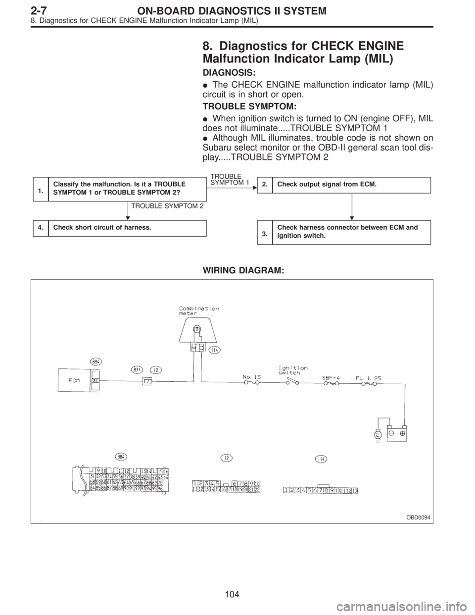
8. Diagnostics for CHECK ENGINE
Malfunction Indicator Lamp (MIL)
DIAGNOSIS:
�The CHECK ENGINE malfunction indicator lamp (MIL)
circuit is in short or open.
TROUBLE SYMPTOM:
�When ignition switch is turned to ON (engine OFF), MIL
does not illuminate.....TROUBLE SYMPTOM 1
�Although MIL illuminates, trouble code is not shown on
Subaru select monitor or the OBD-II general scan tool dis-
play.....TROUBLE SYMPTOM 2
1.Classify the malfunction. Is it a TROUBLE
SYMPTOM 1 or TROUBLE SYMPTOM 2?
TROUBLE SYMPTOM 2
�
TROUBLE
SYMPTOM 1
2.Check output signal from ECM.
4.Check short circuit of harness.3.Check harness connector between ECM and
ignition switch.
WIRING DIAGRAM:
OBD0094
��
104
2-7ON-BOARD DIAGNOSTICS II SYSTEM
8. Diagnostics for CHECK ENGINE Malfunction Indicator Lamp (MIL)
 Disconnect test mode connector at the lower portion of
instrument panel (on the driver’s side), to the side of the
center console box.
2) Turn Subaru sele")

Note Ignition SW
Engine ON (Idling)
ON (Engine OFF)
Starter switch B84 81 0 0 Cranking: 8 to 14
A/C switch B84 80ON: 10—13
OFF: 0ON: 13—14
OFF: 0—
Igni")

Note Ignition SW
Engine ON (Idling)
ON (Engine OFF)
GND (injectors) B8471
00—
72
GND (ignition system) B84 69 0 0—
GND (power supply) B8495
00—
96
GND")