Page 1193 of 2248

E: DIAGNOSTICS PROCEDURE FOR
SECURITY CONTROL MODULE POWER
SUPPLY/GROUND CIRCUIT
1. Check fuse and power supply circuit.
OK
�Not OK
�Replace fuse.
�Repair or replace wiring harness.
2. Check ground circuit between security control
module and body.
OK
�Not OK
Repair or replace wiring harness.
Go to next step on basic diagnostics procedure.
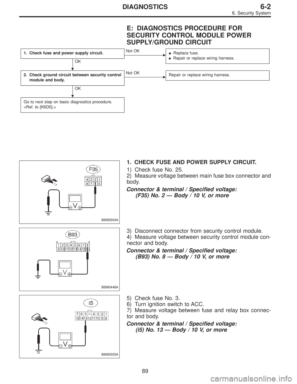
B6M0504A
1. CHECK FUSE AND POWER SUPPLY CIRCUIT.
1) Check fuse No. 25.
2) Measure voltage between main fuse box connector and
body.
Connector & terminal / Specified voltage:
(F35) No. 2—Body / 10 V, or more
B6M0448A
3) Disconnect connector from security control module.
4) Measure voltage between security control module con-
nector and body.
Connector & terminal / Specified voltage:
(B93) No. 8—Body / 10 V, or more
B6M0505A
5) Check fuse No. 3.
6) Turn ignition switch to ACC.
7) Measure voltage between fuse and relay box connec-
tor and body.
Connector & terminal / Specified voltage:
(i5) No. 13—Body / 10 V, or more
�
�
89
6-2DIAGNOSTICS
6. Security System
Page 1194 of 2248
B6M0452A
8) Disconnect connector from security control module.
9) Measure voltage between security control module con-
nector and body.
Connector & terminal / Specified voltage:
(B93) No. 6—Body / 10 V, or more
B6M0497A
2. CHECK GROUND CIRCUIT BETWEEN SECURITY
CONTROL MODULE AND BODY.
1) Turn ignition switch to OFF.
2) Disconnect connector of security control module.
3) Measure resistance of harness connector between
security control module and body.
Connector & terminal / Specified resistance:
(B93) No. 9—Body / 10Ω, max.
90
6-2DIAGNOSTICS
6. Security System
Page 1199 of 2248

J: DIAGNOSTICS PROCEDURE FOR DOOR
LOCK/UNLOCK SWITCH SIGNAL
1. Check door lock/unlock switch input signal
for security control module.
Not OK
�OK
Go to next step on basic diagnostics procedure.
2. Check door lock/unlock switch.
OK
�Not OK
Replace door lock/unlock switch.
Repair or replace wiring harness between door lock/
unlock switch and security control module.
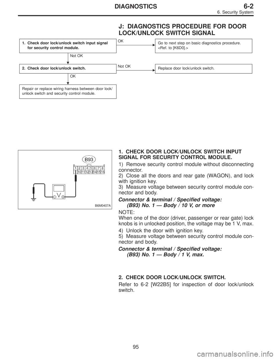
B6M0407A
1. CHECK DOOR LOCK/UNLOCK SWITCH INPUT
SIGNAL FOR SECURITY CONTROL MODULE.
1) Remove security control module without disconnecting
connector.
2) Close all the doors and rear gate (WAGON), and lock
with ignition key.
3) Measure voltage between security control module con-
nector and body.
Connector & terminal / Specified voltage:
(B93) No. 1—Body / 10 V, or more
NOTE:
When one of the door (driver, passenger or rear gate) lock
knobs is in unlocked position, the voltage may be 1 V, max.
4) Unlock the door with ignition key.
5) Measure voltage between security control module con-
nector and body.
Connector & terminal / Specified voltage:
(B93) No. 1—Body/1V,max.
2. CHECK DOOR LOCK/UNLOCK SWITCH.
Refer to 6-2 [W22B5] for inspection of door lock/unlock
switch.
�
�
95
6-2DIAGNOSTICS
6. Security System
Page 1211 of 2248

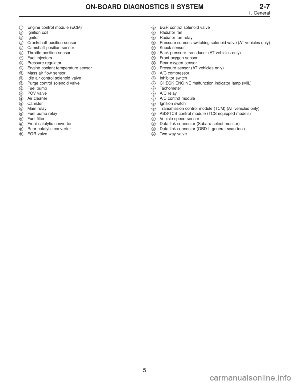
�1Engine control module (ECM)
�
2Ignition coil
�
3Ignitor
�
4Crankshaft position sensor
�
5Camshaft position sensor
�
6Throttle position sensor
�
7Fuel injectors
�
8Pressure regulator
�
9Engine coolant temperature sensor
�
10Mass air flow sensor
�
11Idle air control solenoid valve
�
12Purge control solenoid valve
�
13Fuel pump
�
14PCV valve
�
15Air cleaner
�
16Canister
�
17Main relay
�
18Fuel pump relay
�
19Fuel filter
�
20Front catalytic converter
�
21Rear catalytic converter
�
22EGR valve�
23EGR control solenoid valve
�
24Radiator fan
�
25Radiator fan relay
�
26Pressure sources switching solenoid valve (AT vehicles only)
�
27Knock sensor
�
28Back-pressure transducer (AT vehicles only)
�
29Front oxygen sensor
�
30Rear oxygen sensor
�
31Pressure sensor (AT vehicles only)
�
32A/C compressor
�
33Inhibitor switch
�
34CHECK ENGINE malfunction indicator lamp (MIL)
�
35Tachometer
�
36A/C relay
�
37A/C control module
�
38Ignition switch
�
39Transmission control module (TCM) (AT vehicles only)
�
40ABS/TCS control module (TCS equipped models)
�
41Vehicle speed sensor
�
42Data link connector (Subaru select monitor)
�
43Data link connector (OBD-II general scan tool)
�
44Two way valve
5
2-7ON-BOARD DIAGNOSTICS II SYSTEM
1. General
Page 1219 of 2248
4. SOLENOID VALVE, EMISSION CONTROL SYSTEM
PARTS AND IGNITION SYSTEM PARTS (LHD MODEL)
EQA0051
�1Pressure sources switching solenoid valve
(AT vehicles only)
�
2Idle air control solenoid valve
�
3EGR valve (AT vehicles only)�
4EGR control solenoid valve (AT vehicles only)
�
5Purge control solenoid valve
�
6Ignitor
�
7Ignition coil
OBD0021AOBD0022A
13
2-7ON-BOARD DIAGNOSTICS II SYSTEM
2. Electrical Components Location
Page 1223 of 2248
5. SOLENOID VALVE, EMISSION CONTROL SYSTEM
PARTS AND IGNITION SYSTEM PARTS (RHD MODEL)
EPA0086
�1Pressure sources switching solenoid valve
�
2Idle air control solenoid valve
�
3EGR valve
�
4EGR control solenoid valve�
5Purge control solenoid valve
�
6Ignitor
�
7Ignition coil
OBD0021AOBD0022A
17
2-7ON-BOARD DIAGNOSTICS II SYSTEM
2. Electrical Components Location
Page 1233 of 2248
OBD0008C
3. Diagnosis System
A: MALFUNCTION INDICATOR LAMP (MIL)
1. ACTIVATION OF MALFUNCTION INDICATOR LAMP
(MIL)
1) When ignition switch is turned to ON (engine off), the
CHECK ENGINE malfunction indicator lamp (MIL) in the
combination meter illuminates.
NOTE:
If the MIL does not illuminate, perform diagnostics of the
CHECK ENGINE light circuit or the combination meter cir-
cuit.
function Indicator Lamp (MIL) [T800]”.>
OBD0053A
2) After starting the engine, the MIL goes out. If it does not,
either the engine or the emission control system is mal-
functioning.
OBD0054A
3) If the diagnosis system senses a misfire which could
damage the catalyzer, the MIL will blink at a cycle of 1 Hz.
OBD0055A
4) When ignition switch is turned to ON (engine off) or to
“START” with the test mode connector connected, the MIL
blinks at a cycle of 3 Hz.
27
2-7ON-BOARD DIAGNOSTICS II SYSTEM
3. Diagnosis System
Page 1238 of 2248

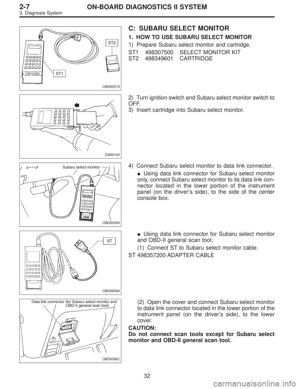
OBD0057A
C: SUBARU SELECT MONITOR
1. HOW TO USE SUBARU SELECT MONITOR
1) Prepare Subaru select monitor and cartridge.
ST1 498307500 SELECT MONITOR KIT
ST2 498349601 CARTRIDGE
G3M0150
2) Turn ignition switch and Subaru select monitor switch to
OFF.
3) Insert cartridge into Subaru select monitor.
OBD0059A
4) Connect Subaru select monitor to data link connector.
�Using data link connector for Subaru select monitor
only, connect Subaru select monitor to its data link con-
nector located in the lower portion of the instrument
panel (on the driver’s side), to the side of the center
console box.
OBD0669A
�Using data link connector for Subaru select monitor
and OBD-II general scan tool;
(1) Connect ST to Subaru select monitor cable.
ST 498357200 ADAPTER CABLE
OBD0006C
(2) Open the cover and connect Subaru select monitor
to data link connector located in the lower portion of the
instrument panel (on the driver’s side), to the lower
cover.
CAUTION:
Do not connect scan tools except for Subaru select
monitor and OBD-II general scan tool.
32
2-7ON-BOARD DIAGNOSTICS II SYSTEM
3. Diagnosis System