Page 1239 of 2248
OBD0060
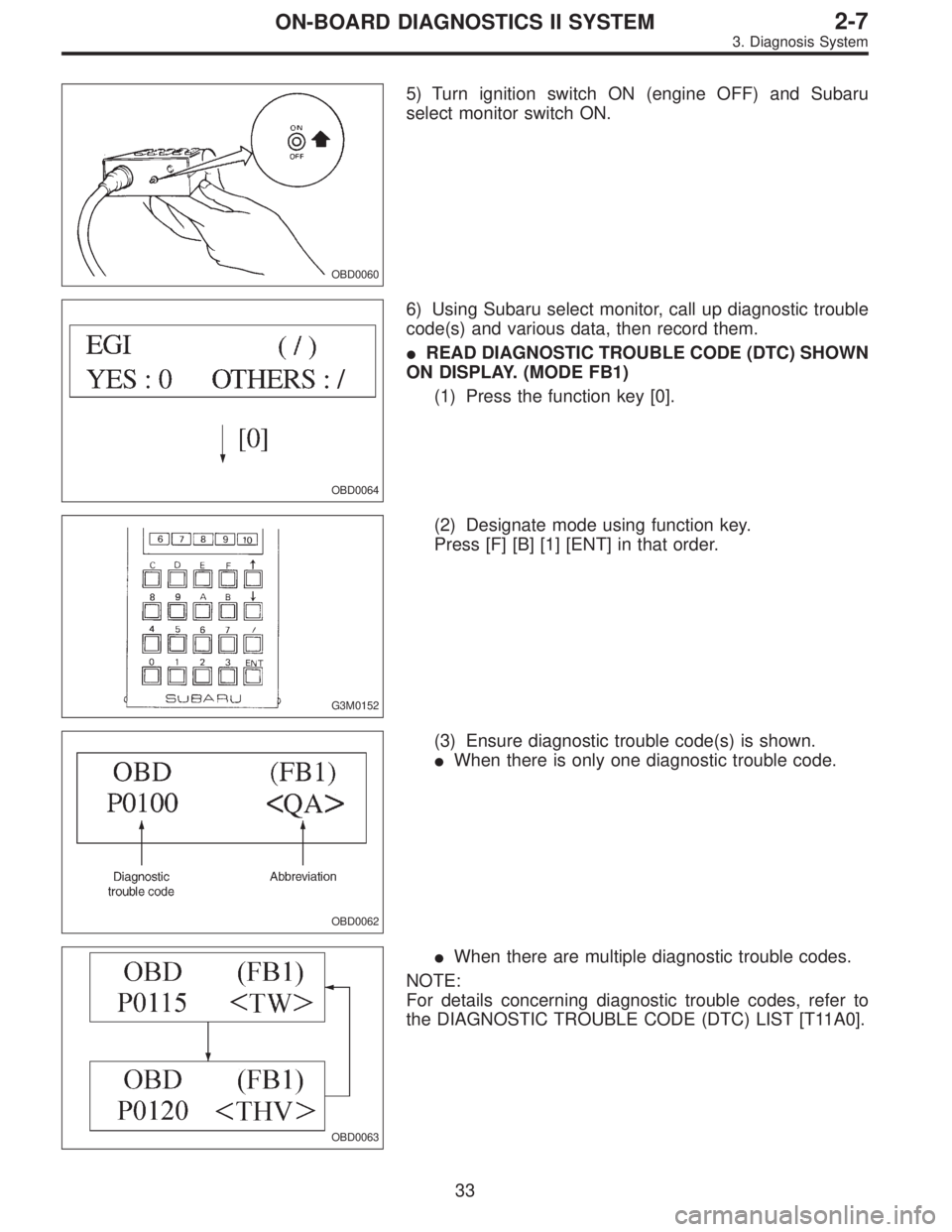
5) Turn ignition switch ON (engine OFF) and Subaru
select monitor switch ON.
OBD0064
6) Using Subaru select monitor, call up diagnostic trouble
code(s) and various data, then record them.
�READ DIAGNOSTIC TROUBLE CODE (DTC) SHOWN
ON DISPLAY. (MODE FB1)
(1) Press the function key [0].
G3M0152
(2) Designate mode using function key.
Press [F] [B] [1] [ENT] in that order.
OBD0062
(3) Ensure diagnostic trouble code(s) is shown.
�When there is only one diagnostic trouble code.
OBD0063
�When there are multiple diagnostic trouble codes.
NOTE:
For details concerning diagnostic trouble codes, refer to
the DIAGNOSTIC TROUBLE CODE (DTC) LIST [T11A0].
33
2-7ON-BOARD DIAGNOSTICS II SYSTEM
3. Diagnosis System
Page 1243 of 2248
OBD0065
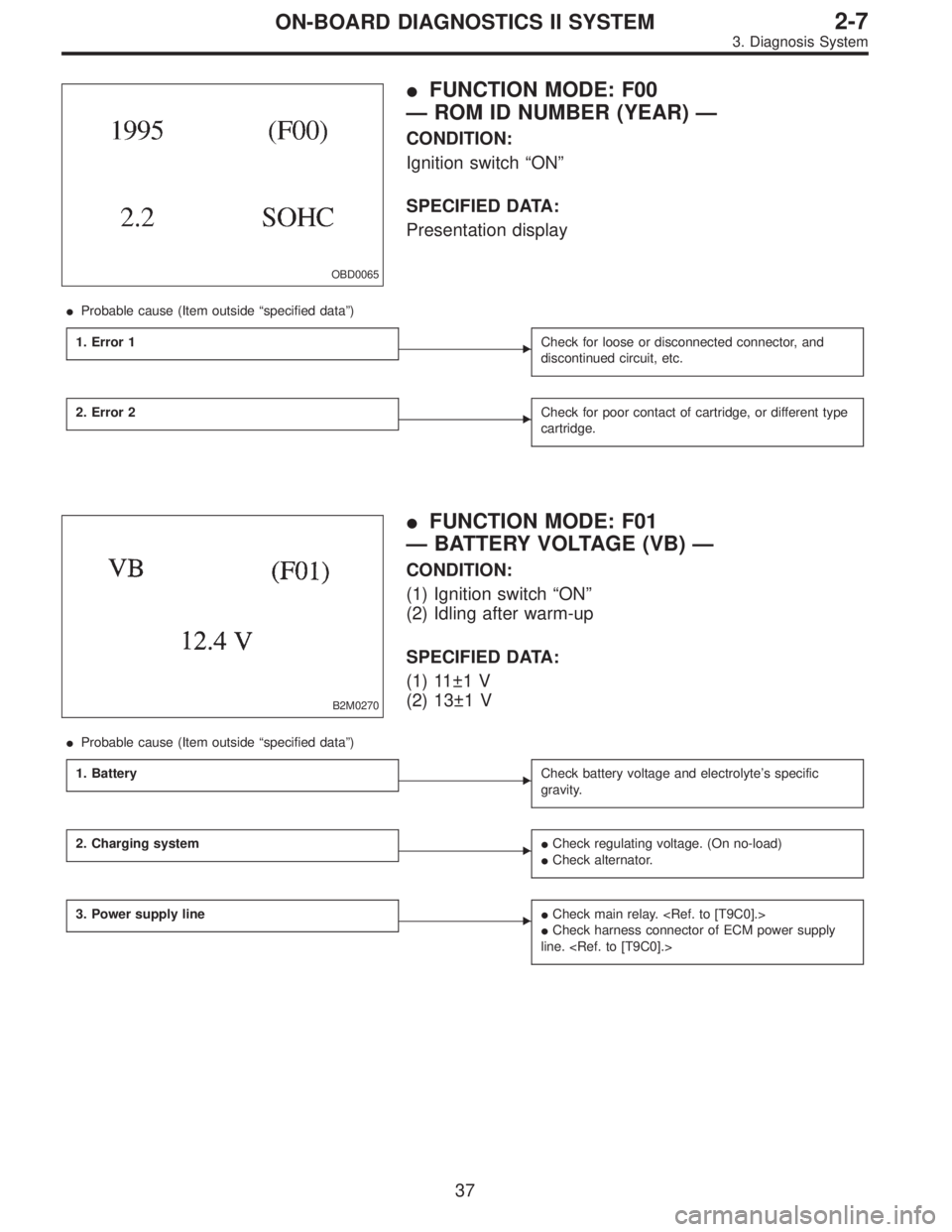
�FUNCTION MODE: F00
— ROM ID NUMBER (YEAR) —
CONDITION:
Ignition switch“ON”
SPECIFIED DATA:
Presentation display
�Probable cause (Item outside“specified data”)
1. Error 1
�Check for loose or disconnected connector, and
discontinued circuit, etc.
2. Error 2�Check for poor contact of cartridge, or different type
cartridge.
B2M0270
�FUNCTION MODE: F01
— BATTERY VOLTAGE (VB) —
CONDITION:
(1) Ignition switch“ON”
(2) Idling after warm-up
SPECIFIED DATA:
(1) 11±1 V
(2) 13±1 V
�Probable cause (Item outside“specified data”)
1. Battery
�Check battery voltage and electrolyte’s specific
gravity.
2. Charging system��Check regulating voltage. (On no-load)
�Check alternator.
3. Power supply line��Check main relay.
�Check harness connector of ECM power supply
line.
37
2-7ON-BOARD DIAGNOSTICS II SYSTEM
3. Diagnosis System
Page 1253 of 2248

3. FA MODE FOR ENGINE
Function
modeLED No. Contents Display LED“ON”requirements
FA 01 Ignition switch IG When ignition switch is turned ON.
2 AT/MT identification signal AT When AT identification signal is entered.
3 Test mode connector UD When test mode connector is connected.
5 Idle speed control identification signal ICWhen engine rpm is less than the established
value.
7 Neutral switch NT When neutral position signal is entered.
FA 12 Air conditioner switch AC When air conditioner switch is turned ON.
3 Air conditioner relay AR When air conditioner relay is in function.
4 Radiator fan relay 1 R1 When radiator fan relay 1 is in function.
5 Radiator fan relay 2 R2 When radiator fan relay 2 is in function.
6 Fuel pump relay FP When fuel pump relay is in function.
7 Purge control solenoid valve CP When purge control solenoid valve is in function.
9 Pressure sources switching solenoid valve BRWhen pressure sources switching solenoid valve
is in function.
FA 23 EGR solenoid valve EG When EGR solenoid valve is in function.
4 Engine torque control signal TR When engine torque control signal is entered.
5 Engine torque control cut signal TC When engine torque control cut signal is got out.
9 Front oxygen sensor signal FO When front oxygen sensor mixture ratio is rich.
10 Rear oxygen sensor signal RO When rear oxygen sensor mixture ratio is rich.
47
2-7ON-BOARD DIAGNOSTICS II SYSTEM
3. Diagnosis System
Page 1254 of 2248

LED No. Signal name Display
1 Ignition switch IG
2 Identification of AT model AT
3 Test mode connector UD
4——
5 ISC identification IC
6——
7Park/Neutral position
switchNT
8——
9——
10——
IG AT UD ID IC
—NT———
1
2345
678910
�FUNCTION MODE: FA0
—ON↔OFF SIGNAL—
Requirement for LED“ON”.
LED No. 1 Ignition switch is turned ON.
LED No. 2 Vehicle is AT model.
LED No. 3 Test mode connector is connected.
LED No. 5 Engine speed is less than the specified
value.
LED No. 7�On MT model, gear position is in neutral.
�On AT model, shift position is in“P”or“N”.
LED No. Signal name Display
1——
2 A/C switch AC
3 A/C relay AR
4 Radiator fan relay 1 R1
5 Radiator fan relay 2 R2
6 Fuel pump relay FP
7Purge control solenoid
valveCP
8——
9Pressure sources switching
solenoid valveBR
10——
—AC AR R1 R2
FP CP—BR—
1
2345
678910
�FUNCTION MODE: FA1
—ON↔OFF SIGNAL—
Requirement for LED“ON”.
LED No. 2 A/C switch is turned ON.
LED No. 3 A/C relay is turned ON.
LED No. 4 Radiator fan relay 1 is turned ON.
LED No. 5 Radiator fan relay 2 is turned ON.
LED No. 6 Fuel pump relay is turned ON.
LED No. 7 Purge control solenoid valve is in function.
LED No. 9 Pressure sources switching solenoid valve is
in function.
NOTE:
�When LED No. 3, 4, 5, 6, 7 and 9 blinks with the test
mode connector connected and the ignition switch turned
to ON, the corresponding part is functioning properly.
�When LED No. 6 illuminates for only 2 seconds after the
ignition switch is turned to ON, (and then goes out), the
corresponding part is functioning properly.
48
2-7ON-BOARD DIAGNOSTICS II SYSTEM
3. Diagnosis System
Page 1258 of 2248
G3M0723
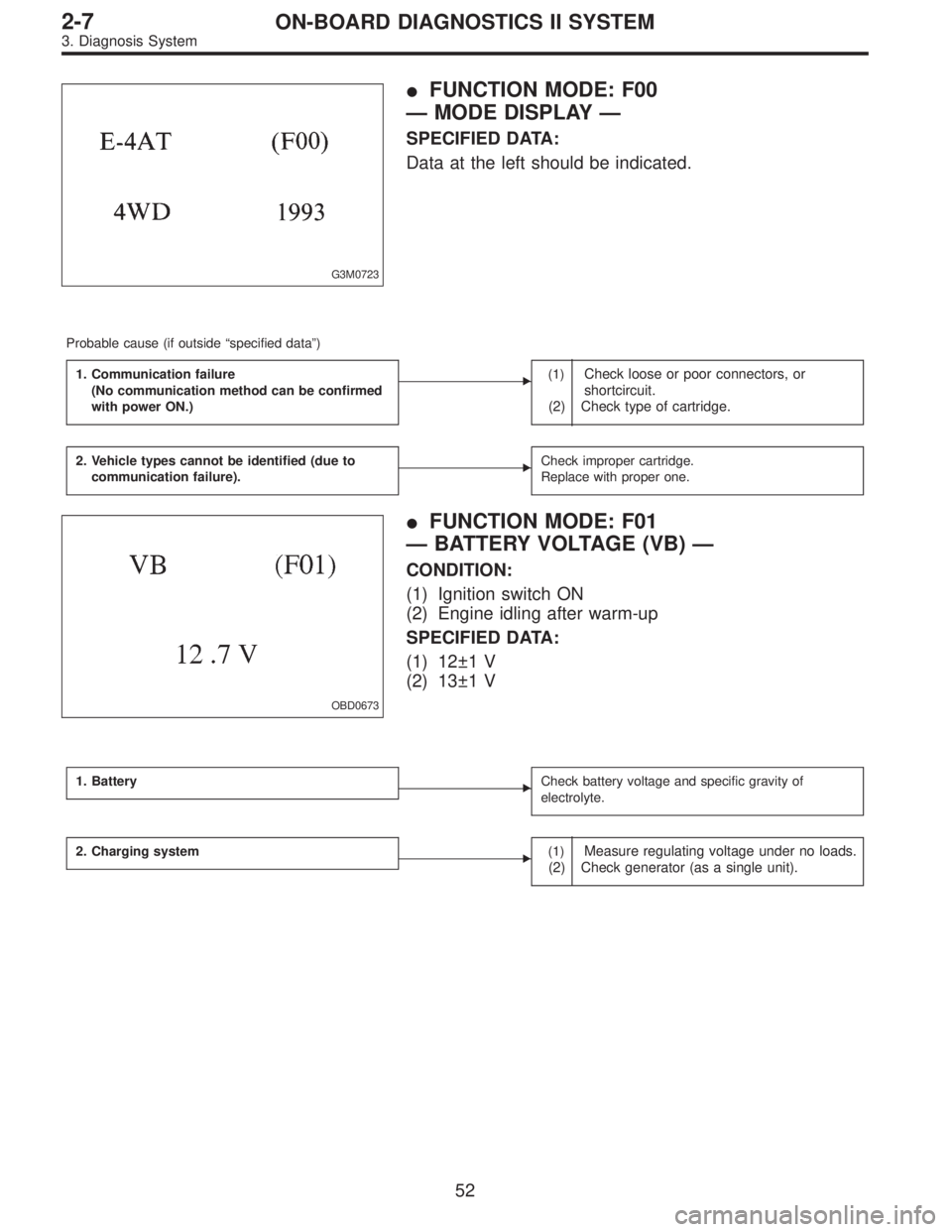
�FUNCTION MODE: F00
—MODE DISPLAY—
SPECIFIED DATA:
Data at the left should be indicated.
Probable cause (if outside“specified data”)
1. Communication failure
(No communication method can be confirmed
with power ON.)
�(1)Check loose or poor connectors, or
shortcircuit.
(2) Check type of cartridge.
2. Vehicle types cannot be identified (due to
communication failure).�Check improper cartridge.
Replace with proper one.
OBD0673
�FUNCTION MODE: F01
—BATTERY VOLTAGE (VB)—
CONDITION:
(1) Ignition switch ON
(2) Engine idling after warm-up
SPECIFIED DATA:
(1) 12±1 V
(2) 13±1 V
1. Battery�Check battery voltage and specific gravity of
electrolyte.
2. Charging system�(1)Measure regulating voltage under no loads.
(2) Check generator (as a single unit).
52
2-7ON-BOARD DIAGNOSTICS II SYSTEM
3. Diagnosis System
Page 1264 of 2248
 After the display is gone, turn Subaru select monitor
switch and ignition switch to OFF.
NOTE:
When the ECM, battery terminals, etc. are disconnected
after memory is cleared, idling speed m")
G3M0151
6) After the display is gone, turn Subaru select monitor
switch and ignition switch to OFF.
NOTE:
When the ECM, battery terminals, etc. are disconnected
after memory is cleared, idling speed may increase. This is
not considered a problem because the ISC valve duty con-
trolled learning value has been cleared. To return the
engine to idling speed, idle for approximately 2 minutes
with air conditioner off.
2. OBD-II GENERAL SCAN TOOL
For clear memory procedures using the OBD-II general
scan tool, refer to the OBD-II General Scan Tool Instruction
Manual.
OBD0072A
E: INSPECTION MODE
1. PREPARATIONS FOR THE INSPECTION MODE
Raise the vehicle using a garage jack and place on safety
stands or drive the vehicle onto free rollers.
�FULL-TIME AWD MODELS
WARNING:
�Before raising the vehicle, ensure parking brakes
are applied.
�Do not use a pantograph jack in place of a safety
stand.
�Secure a rope or wire to the front and rear towing or
tie-down hooks to prevent the lateral runout of front
wheels.
�Do not abruptly depress/release clutch pedal or
accelerator pedal during works even when engine is
operating at low speeds since this may cause vehicle
to jump off free rollers.
�In order to prevent the vehicle from slipping due to
vibration, do not place any wooden blocks or similar
items between the safety stands and the vehicle.
58
2-7ON-BOARD DIAGNOSTICS II SYSTEM
3. Diagnosis System
Page 1266 of 2248
OBD0057A
2. SUBARU SELECT MONITOR
After performing diagnostics and clearing the memory,
check for any remaining unresolved trouble data.
1) Prepare Subaru select monitor and cartridge.
ST1 498307500 SELECT MONITOR KIT
ST2 498349601 CARTRIDGE
G3M0151
2) Turn ignition switch and monitor switch to OFF.
G3M0150
3) Insert cartridge into Subaru select monitor.
OBD0005B
4) Connect test mode connector at the lower portion of
instrument panel (on the driver’s side), to the side of the
center console box.
OBD0059A
5) Connect Subaru select monitor to data link connector.
�Using data link connector for Subaru select monitor only:
Connect Subaru select monitor to its data link connector
located in the lower portion of the instrument panel (on the
driver’s side), to the side of the center console box.
60
2-7ON-BOARD DIAGNOSTICS II SYSTEM
3. Diagnosis System
Page 1267 of 2248
 Connect ST to Subaru select monitor cable.
ST 498357200 ADAPTER CABLE
OBD0006C
(2) Open the cover and co")
OBD0669A
�Using data link connector for Subaru select monitor and
OBD-II general scan tool:
(1) Connect ST to Subaru select monitor cable.
ST 498357200 ADAPTER CABLE
OBD0006C
(2) Open the cover and connect Subaru select monitor
to data link connector located in the lower portion of the
instrument panel (on the driver’s side), to the lower
cover.
CAUTION:
Do not connect scan tools except for Subaru select
monitor and OBD-II general scan tool.
OBD0060
6) Turn ignition switch ON (engine OFF) and Subaru
select monitor switch ON.
7) Start the engine.
NOTE:
�Ensure the selector lever is placed in the“P”position
before starting. (AT vehicles)
�Depress clutch pedal when starting the engine. (MT
vehicles)
8) Using the selector lever or shift lever, turn the“P”posi-
tion switch and the“N”position switch to ON.
9) Depress the brake pedal to turn the brake switch ON.
(AT vehicles)
10) Keep engine speed in the 2,500—3,000 rpm range
for 40 seconds.
NOTE:
On models without tachometer, use the Subaru select
monitor or tachometer (Secondary pickup type).
11) Place the selector lever or shift lever in the“D”posi-
tion (AT vehicles) or“1st”gear (MT vehicles) and drive the
vehicle at 5 to 10 km/h (3 to 6 MPH).
NOTE:
�On AWD vehicles, release the parking brake.
�The speed difference between front and rear wheels
may light either the ABS or the ABS/TCS warning light, but
this indicates no malfunctions. When engine control diag-
nosis is finished, perform the ABS or the ABS/TCS memory
clearance procedure of self-diagnosis system.
4-4a [T6C2] or 4-4b [T6C2] or [T9K0].>
61
2-7ON-BOARD DIAGNOSTICS II SYSTEM
3. Diagnosis System
 Prepare Subaru select monitor and cartridge.
ST1 498307500 S")