Page 1102 of 2248
![SUBARU LEGACY 1995 Service Repair Manual CAUTION:
�Observe the items in 1. NORMAL CHARGING
[W2C1].
�Never use more than 10 amperes when charging the
battery because that will shorten battery life.
3. JUDGMENT OF BATTERY IN CHARGED
CONDITION
SUBARU LEGACY 1995 Service Repair Manual CAUTION:
�Observe the items in 1. NORMAL CHARGING
[W2C1].
�Never use more than 10 amperes when charging the
battery because that will shorten battery life.
3. JUDGMENT OF BATTERY IN CHARGED
CONDITION](/manual-img/17/57432/w960_57432-1101.png)
CAUTION:
�Observe the items in 1. NORMAL CHARGING
[W2C1].
�Never use more than 10 amperes when charging the
battery because that will shorten battery life.
3. JUDGMENT OF BATTERY IN CHARGED
CONDITION
1) Specific gravity of electrolyte is held at a specific value
in a range from 1.250 to 1.290 for more than one hour.
2) Voltage per battery cell is held at a specific value in a
range from 2.5 to 2.8 volts for more than one hour.
4. CHECK HYDROMETER FOR STATE OF CHARGE
Hydrometer indicator State of charge Required action
Green dot Above 65% Load test
Dark dot Below 65% Charge battery
Clear dot Low electrolyteReplace battery.* (If
cranking complaint)
*: Check electrical system before replacement.
B6M0236
3. Ignition Switch
A: REMOVAL AND INSTALLATION
1. IGNITION SWITCH
1) Remove screws, separate upper column cover and
lower column cover.
2) Remove instrument panel lower cover.
B6M0333
3) Disconnect ignition switch connector from body har-
ness.
4) Using a drift and hammer, hit the torn bolt head to
loosen and remove the ignition switch.
B6M0334A
5) When installing, tighten the connecting bolt until its
head twists off.
7
6-2SERVICE PROCEDURE
2. Battery - 3. Ignition Switch
Page 1103 of 2248
![SUBARU LEGACY 1995 Service Repair Manual CAUTION:
�Observe the items in 1. NORMAL CHARGING
[W2C1].
�Never use more than 10 amperes when charging the
battery because that will shorten battery life.
3. JUDGMENT OF BATTERY IN CHARGED
CONDITION
SUBARU LEGACY 1995 Service Repair Manual CAUTION:
�Observe the items in 1. NORMAL CHARGING
[W2C1].
�Never use more than 10 amperes when charging the
battery because that will shorten battery life.
3. JUDGMENT OF BATTERY IN CHARGED
CONDITION](/manual-img/17/57432/w960_57432-1102.png)
CAUTION:
�Observe the items in 1. NORMAL CHARGING
[W2C1].
�Never use more than 10 amperes when charging the
battery because that will shorten battery life.
3. JUDGMENT OF BATTERY IN CHARGED
CONDITION
1) Specific gravity of electrolyte is held at a specific value
in a range from 1.250 to 1.290 for more than one hour.
2) Voltage per battery cell is held at a specific value in a
range from 2.5 to 2.8 volts for more than one hour.
4. CHECK HYDROMETER FOR STATE OF CHARGE
Hydrometer indicator State of charge Required action
Green dot Above 65% Load test
Dark dot Below 65% Charge battery
Clear dot Low electrolyteReplace battery.* (If
cranking complaint)
*: Check electrical system before replacement.
B6M0236
3. Ignition Switch
A: REMOVAL AND INSTALLATION
1. IGNITION SWITCH
1) Remove screws, separate upper column cover and
lower column cover.
2) Remove instrument panel lower cover.
B6M0333
3) Disconnect ignition switch connector from body har-
ness.
4) Using a drift and hammer, hit the torn bolt head to
loosen and remove the ignition switch.
B6M0334A
5) When installing, tighten the connecting bolt until its
head twists off.
7
6-2SERVICE PROCEDURE
2. Battery - 3. Ignition Switch
Page 1104 of 2248

B6M0048
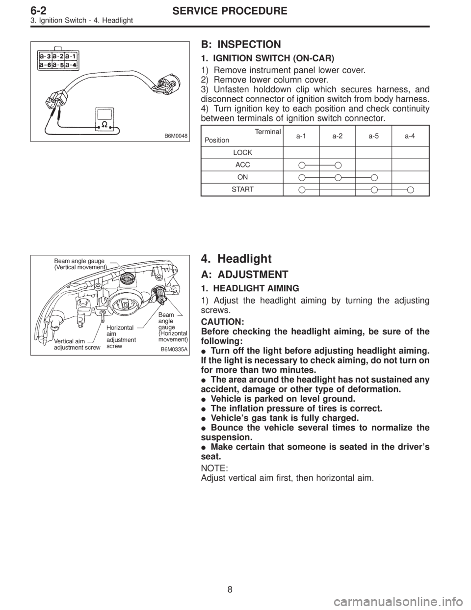
B: INSPECTION
1. IGNITION SWITCH (ON-CAR)
1) Remove instrument panel lower cover.
2) Remove lower column cover.
3) Unfasten holddown clip which secures harness, and
disconnect connector of ignition switch from body harness.
4) Turn ignition key to each position and check continuity
between terminals of ignition switch connector.
Terminal
Positiona-1 a-2 a-5 a-4
LOCK
ACC��
ON���
START���
B6M0335A
4. Headlight
A: ADJUSTMENT
1. HEADLIGHT AIMING
1) Adjust the headlight aiming by turning the adjusting
screws.
CAUTION:
Before checking the headlight aiming, be sure of the
following:
�Turn off the light before adjusting headlight aiming.
If the light is necessary to check aiming, do not turn on
for more than two minutes.
�The area around the headlight has not sustained any
accident, damage or other type of deformation.
�Vehicle is parked on level ground.
�The inflation pressure of tires is correct.
�Vehicle’s gas tank is fully charged.
�Bounce the vehicle several times to normalize the
suspension.
�Make certain that someone is seated in the driver’s
seat.
NOTE:
Adjust vertical aim first, then horizontal aim.
8
6-2SERVICE PROCEDURE
3. Ignition Switch - 4. Headlight
Page 1105 of 2248

B6M0048
B: INSPECTION
1. IGNITION SWITCH (ON-CAR)
1) Remove instrument panel lower cover.
2) Remove lower column cover.
3) Unfasten holddown clip which secures harness, and
disconnect connector of ignition switch from body harness.
4) Turn ignition key to each position and check continuity
between terminals of ignition switch connector.
Terminal
Positiona-1 a-2 a-5 a-4
LOCK
ACC��
ON���
START���
B6M0335A
4. Headlight
A: ADJUSTMENT
1. HEADLIGHT AIMING
1) Adjust the headlight aiming by turning the adjusting
screws.
CAUTION:
Before checking the headlight aiming, be sure of the
following:
�Turn off the light before adjusting headlight aiming.
If the light is necessary to check aiming, do not turn on
for more than two minutes.
�The area around the headlight has not sustained any
accident, damage or other type of deformation.
�Vehicle is parked on level ground.
�The inflation pressure of tires is correct.
�Vehicle’s gas tank is fully charged.
�Bounce the vehicle several times to normalize the
suspension.
�Make certain that someone is seated in the driver’s
seat.
NOTE:
Adjust vertical aim first, then horizontal aim.
8
6-2SERVICE PROCEDURE
3. Ignition Switch - 4. Headlight
Page 1154 of 2248

C: DRIVING TESTS
Conduct road tests by selecting a smooth, flat road or use
free rollers as road test simulation.
1. MAIN SWITCH
1) Turn ignition switch ON.
2) Check that indicator light comes on when main switch
is pressed (ON).
3) Check that indicator light goes out when main switch is
pressed again (OFF).
4) Turn ignition switch OFF with main switch ON (which is
indicated by illumination.).
5) Turn ignition switch ON again to ensure that indicator
light remains OFF.
2. COMMAND SWITCH
1) Check that command switch is properly set in“SET/
COAST”,“RESUME/ACCEL”or“CANCEL”mode.
2) Also check that command switch returns to the original
position when released.
3. CONSTANT SPEED TEST
1) Turn main switch ON.
2) Drive vehicle at speed greater than 40 km/h (25 MPH).
3) Press command switch to set in“SET/COAST”mode.
4) Ensure that vehicle is maintained at the speed set when
command switch was pressed.
4. ACCELERATION TEST
1) Set vehicle speed at speed greater than 40 km/h (25
MPH).
2) Ensure that vehicle continues to accelerate while hold-
ing command switch in RESUME/ACCEL mode, and that
vehicle maintains that optional speed when command
switch is released.
5. DECELERATION TEST
1) Set vehicle speed at optional speed greater than 40
km/h (25 MPH).
2) Ensure that vehicle continues to decelerate while hold-
ing command switch in SET/COAST mode, and that it
maintains that optional speed when command switch is
released.
NOTE:
When vehicle speed reaches the lower speed limit of 30
km/h (19 MPH) during deceleration, cruise control will be
released.
50
6-2SERVICE PROCEDURE
21. Cruise Control
Page 1160 of 2248
B6M0377
4. KEY CYLINDER LOCK/UNLOCK SWITCH AND
TAMPER SWITCH
Door Switch
1) Disconnect connector of door key cylinder switch.
2) Move switch by turning the key cylinder with ignition key
and/or remove switch from key cylinder to check continuity
between terminals as indicated in table below:
Terminal
Switch position1234
Normal
LOCK��
UNLOCK��
Switch is removed from
key cylinder.��
B6M0378A
Trunk Lid Switch (SEDAN)
1) Disconnect connector of trunk lid key cylinder switch.
2) Move switch by turning the key cylinder with ignition key
and/or remove switch from key cylinder to check continuity
between terminals as indicated in table below:
Terminal
Switch position123
Normal
UNLOCK��
Switch is removed from
key cylinder.��
56
6-2SERVICE PROCEDURE
22. Security System
Page 1161 of 2248
B6M0379
Rear Gate Switch (WAGON)
1) Disconnect connector of rear gate key cylinder switch.
2) Move switch by turning the key cylinder with ignition key
and check continuity between terminals as indicated in
table below:
Terminal
Switch position124
Normal
LOCK��
UNLOCK��
B6M0133A
B6M0381A
5. DOOR LOCK/UNLOCK SWITCH
NOTE:
The door lock/unlock switch is united with the power door
lock actuator.
1) Disconnect connector of door lock/unlock switch.
2) Set switch to each position and check continuity
between terminals as indicated in table below:
Driver’s Door
Terminal
Switch position12
UNLOCK��
LOCK
Passenger’s Door
Terminal
Switch position1234
UNLOCK��
LOCK
Rear Gate (WAGON)
Terminal
Switch position1234
UNLOCK��
LOCK
57
6-2SERVICE PROCEDURE
22. Security System
Page 1163 of 2248

C: FUNCTION TEST
1. SECURITY SYSTEM OPERATION
1) Fully open all the door windows.
2) Turn the ignition switch to OFF and remove ignition key
from ignition switch.
3) Get out of the vehicle and lock the driver’s door using a
ignition key.
4) Check that the security indicator light illuminates.
5) When the security indicator light illuminates, wait for 30
seconds.
After 30 seconds, check that the light starts repeating 0.2
sec. ON and 2.4 sec. OFF sequence.
6) Unlock the driver’s door using the inside lock knob and
open the door.
Ensure that:
(1) the horn sounds and headlights flash intermittently
at 0.2 sec. ON and 0.6 sec. OFF. intervals, and
(2) the engine will not start even if the ignition switch
is turned to START.
7) Unlock the driver’s door one time using the ignition key.
Ensure the horn and headlights turn off.
8) Close and lock the driver’s door without using a ignition
key. (Set the inside lock knob to LOCK and then close the
door while lifting the outer handle).
Check that the security indicator light illuminates continu-
ously.
9) Within 30 seconds after the above step 8), unlock the
rear LH door using the inside lock knob and open the door.
Check that the security indicator light flashes at 0.5 sec.
intervals.
10) Close the rear LH door and lock the door using the
inside lock knob.
Check that the security indicator light illuminates continu-
ously.
11) Perform the above steps 9) and 10) on the rear RH
door and front RH door.
12) Within 30 seconds after above step 11) has been
finished, pull the engine hood opener lever and open the
engine hood.
Check that the security indicator light flashes at 0.5 sec.
intervals.
13) Close the engine hood completely.
Check that the security indicator light illuminates continu-
ously.
59
6-2SERVICE PROCEDURE
22. Security System