Page 149 of 2248
 Check fuse No. 13.
2) Turn ignition switch to ACC.
3) Measure voltage between fuse and relay box, and body.
Connector & terminal / Specified voltage:
(F40)")
B2M0427A
1. CHECK FUSE AND POWER SUPPLY.
1) Check fuse No. 13.
2) Turn ignition switch to ACC.
3) Measure voltage between fuse and relay box, and body.
Connector & terminal / Specified voltage:
(F40) No. 3—Body / 10 V, or more
B2M0377A
2. CHECK HARNESS CONNECTOR BETWEEN FUSE
AND RELAY BOX, AND SUB FAN MOTOR.
1) Turn ignition switch to OFF.
2) Disconnect connectors from fuse and relay box, and
sub fan motor.
3) Measure resistance of harness connector between fuse
and relay box, and sub fan motor.
Connector & terminal / Specified resistance:
(F40) No. 3—(F16) No. 2 / 10Ω, max.
B2M0378A
3. CHECK GROUND CIRCUIT OF SUB FAN MOTOR.
Measure resistance between sub fan motor connector and
body.
Connector & terminal / Specified resistance:
(F16) No. 1—Body / 10Ω, max.
B2M0372A
4. CHECK SUB FAN MOTOR.
1) Disconnect connector from sub fan motor.
2) Connect battery positive (+) terminal to terminal No. 2
and connect terminal No. 1 to ground. Ensure that fan
rotates at LO speed.
31
2-5DIAGNOSTICS
3. Radiator Sub Fan (With A/C model only)
Page 151 of 2248
![SUBARU LEGACY 1995 Service Repair Manual 1. CHECK OPERATION OF SUB FAN MOTOR LO
MODE.
Check that radiator sub fan rotates at LO speed under each
condition described under LO mode operation. <Ref. to 2-5
[K3A0].>
B2M0379A
2. CHECK POWER SUPPL](/manual-img/17/57432/w960_57432-150.png "SUBARU LEGACY 1995 Service Repair Manual 1. CHECK OPERATION OF SUB FAN MOTOR LO
MODE.
Check that radiator sub fan rotates at LO speed under each
condition described under LO mode operation. <Ref. to 2-5
[K3A0].>
B2M0379A
2. CHECK POWER SUPPL")
1. CHECK OPERATION OF SUB FAN MOTOR LO
MODE.
Check that radiator sub fan rotates at LO speed under each
condition described under LO mode operation.
[K3A0].>
B2M0379A
2. CHECK POWER SUPPLY TO SUB FAN RELAY-2.
1) Turn ignition switch to OFF.
2) Disconnect connector from A/C relay holder.
3) Measure voltage between A/C relay holder connector
and body.
Connector & terminal / Specified voltage:
(F29) No. 1—Body / 1 V, max.
(F29) No. 2—Body / 1 V, max.
4) Turn ignition switch to ON.
5) Measure voltage between A/C relay holder connector
and body.
Connector & terminal / Specified voltage:
(F29) No. 1—Body / 10 V, or more
(F29) No. 2—Body / 10 V, or more
B2M0370A
3. CHECK SUB FAN RELAY-2.
1) Turn ignition switch to OFF.
2) Remove sub fan relay-2 from A/C relay holder.
3) Check continuity between terminals (indicated in table
below) when terminal (1) is connected to battery and ter-
minal (3) is grounded.
When current flows.Between terminals (2)
and (4)Continuity exists.
When current does not
flow.Between terminals (2)
and (4)Continuity does not
exist.
Between terminals (1)
and (3)Continuity exists.
33
2-5DIAGNOSTICS
3. Radiator Sub Fan (With A/C model only)
Page 174 of 2248
 Disconnect connector from throttle position sensor.
2) Remove throttle position sensor holding screws, and
remove it.
3) Installation")
B2M0162
9. Throttle Position Sensor
A: REMOVAL AND INSTALLATION
1) Disconnect connector from throttle position sensor.
2) Remove throttle position sensor holding screws, and
remove it.
3) Installation is in the reverse order of removal.
Tightening torque:
2.2±0.2 N⋅m (0.22±0.02 kg-m, 1.6±0.1 ft-lb)
CAUTION:
When installing throttle position sensor, adjust to the
specified data.
B2M0163
B: ADJUSTMENT
1) Turn ignition switch to OFF.
2) Loosen throttle position sensor holding screws.
G2M0415
3) When using voltage meter;
(1) Take out ECM.
(2) Turn ignition switch to ON.
(3) Adjust throttle position sensor so that signal voltage
to ECM may be in specification.
Connector & Terminal / Specified voltage
(B84) No. 24 — (B84) No. 25 / 0.45 — 0.55 V
[Fully closed.]
(4) Tighten throttle position sensor holding screws.
G2M0096
4) When using Subaru Select Monitor;
(1) Connect Subaru Select Monitor to the data link con-
nector.
(2) Turn ignition switch to ON and SSM switch to ON.
(3) Select mode “F10”.
(4) Adjust throttle position sensor to specified data.
Condition / Specified data.
Throttle fully closed / 0.50 V
(5) Tighten throttle position sensor holding screws.
21
2-7SERVICE PROCEDURE
9. Throttle Position Sensor
Page 190 of 2248
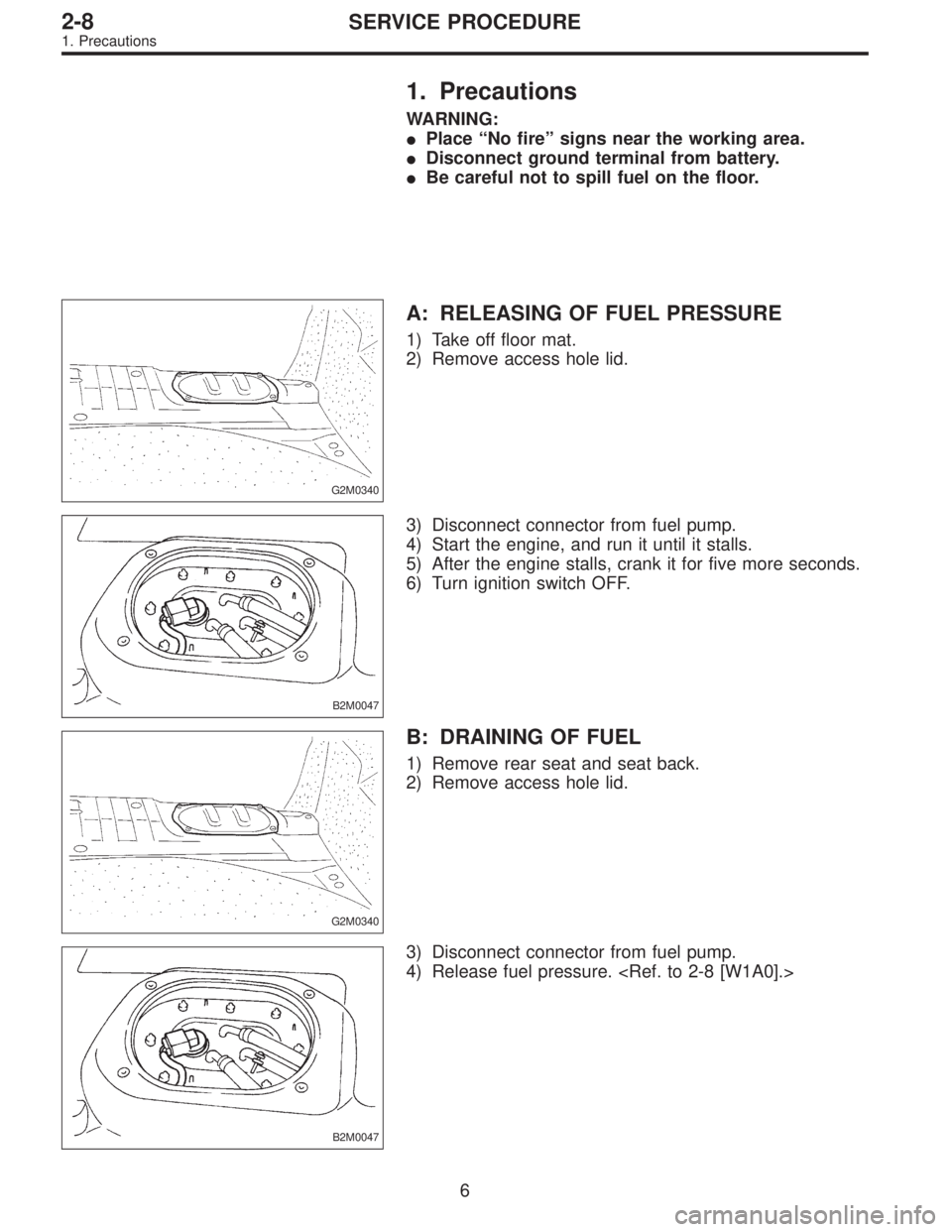
1. Precautions
WARNING:
�Place “No fire” signs near the working area.
�Disconnect ground terminal from battery.
�Be careful not to spill fuel on the floor.
G2M0340
A: RELEASING OF FUEL PRESSURE
1) Take off floor mat.
2) Remove access hole lid.
B2M0047
3) Disconnect connector from fuel pump.
4) Start the engine, and run it until it stalls.
5) After the engine stalls, crank it for five more seconds.
6) Turn ignition switch OFF.
G2M0340
B: DRAINING OF FUEL
1) Remove rear seat and seat back.
2) Remove access hole lid.
B2M0047
3) Disconnect connector from fuel pump.
4) Release fuel pressure.
6
2-8SERVICE PROCEDURE
1. Precautions
Page 241 of 2248
1) Set the vehicle on lift arms.
2) Open front hood fully and support with stay.
G2M0341
3) Release fuel pressure.
(1) Disconnect fuel tank connector.
(2) Start the engine, and run until it stalls.
(3) After the engine stalls, crank it for five seconds
more.
(4) Turn ignition switch to“OFF”.
G6M0095
4) Disconnect battery cables and remove battery from
vehicle.
B2M0015A
5) Drain coolant.
Set container under the vehicle, and remove drain cock
from radiator.
G2M0263
6) Remove cooling system.
(1) Disconnect radiator fan motor connector.
(2) Disconnect radiator outlet hose from thermostat
cover.
7
2-11SERVICE PROCEDURE
2. Engine
Page 372 of 2248

G3M0291
2. INHIBITOR SWITCH
The inhibitor switch allows the back-up lights to turn on
when the select lever is in the R range and the starter
motor to start when the lever is in the N or P range. It also
monitors the input signal electronically controlled for each
range and turns on the corresponding range light on the
instrument panel.
When light operation, driving condition or starter motor
operation is erroneous, first check the shift linkage for
improper operation. If the shift linkage is functioning
properly, check the inhibitor switch.
(1) Disconnect cable end from select lever.
(2) Disconnect inhibitor switch connector.
(3) Check continuity in inhibitor switch circuits with
select lever moved to each position.
CAUTION:
Also check that continuity in ignition circuit does not
exist when selector lever is in R, D, 3, 2 and 1 ranges.
PinNo. 432187651211109
Lead color
B Y Br YG W BY R GW BY BW BW RW
Position
P��
��
R����
N����
D��
3��
2��
1��
Signal sent to AT control unit Ignition circuitBack-up light
circuit
B3H0016A
28
3-2SERVICE PROCEDURE
2. On-Car Service
Page 477 of 2248
 Insert the thread portion of the other inner cable end
into the connector hole of the selector lever, and fix the
other outer cable end to the bracket.
9) Adjust the inner cable length.
(1")
B3M0417A
8) Insert the thread portion of the other inner cable end
into the connector hole of the selector lever, and fix the
other outer cable end to the bracket.
9) Adjust the inner cable length.
(1) Put connector into contact with nut�
2.
(2) Tighten nut�
1.
Tightening torque:
7.4±2.0 N⋅m (0.75±0.2 kg-m, 5.4±1.4 ft-lb)
10) After completion of fitting, make sure that the selector
lever operates smoothly all across the operating range.
11) Connect the harnesses and check the following items.
(1) The engine starts operating when selector lever is
in position“P”, but not in other positions.
(2) The back-up light is lit when the selector lever is in
position“R”, but not in other positions.
B3M0348A
12) Check selector lever operation.
WARNING:
Stop the engine while checking operation of selector
lever.
(1) Check that selector lever does not move from“N”
to“R”without pushing the button.
(2) Check that selector lever does not move from“R”
to“P”without pushing the button.
(3) Check that selector lever does not move from“P”
to“R”without pushing the button and the brake pedal
depressed. [With ignition key set at“ON”.]
(4) Check that selector lever does not move from“3”to
“2”without pushing the button.
13) Check shift-lock system.
(1) Ensure ignition switch rotates from“ACC”to
“LOCK”when the selector lever is set at“P”. Also check
that ignition key can be removed from the“LOCK”posi-
tion only.
(2) Ensure selector lever moves from“P”to any other
position when the brake pedal is depressed with igni-
tion key set at“ON”or“START”.
16
3-3SERVICE PROCEDURE
2. Automatic Transmission
Page 627 of 2248
 Remove steering wheel nut, then draw out steering
wheel from shaft using steering puller.
G4M0086
5) Remove universal joint bolts and then remove universal
joint.
CAUTION:
Scribe alignment")
G5M0332
4) Remove steering wheel nut, then draw out steering
wheel from shaft using steering puller.
G4M0086
5) Remove universal joint bolts and then remove universal
joint.
CAUTION:
Scribe alignment marks on universal joint so that it can
be reassembled at the original serration.
6) Remove trim panel under instrument panel.
7) Disconnect connectors for ignition switch and combina-
tion switch wiring harness under instrument panel.
B4M0127A
8) Remove the two bolts under instrument panel securing
steering shaft.
9) Pull out steering shaft assembly from hole on toe board.
CAUTION:
Be sure to remove universal joint before removing
steering shaft assembly installing bolts when remov-
ing steering shaft assembly or when lowering it for
servicing of other parts.
B4M0555
B: DISASSEMBLY
Remove the four screws securing upper and lower steer-
ing column covers, and the two screws securing combina-
tion switch, then remove related parts.
NOTE:
Steering column assembly can not to be disassembled.
11
4-3SERVICE PROCEDURE
2. Tilt Steering Column
 Set the vehicle on lift arms.
2) Open front hood fully and support with stay.
G2M0341
3) Release fuel pressure.
(1) Disconnect fuel tank connector.
(2) Start the engine, and run until it stalls.
(3")