Page 814 of 2248

F: TCS SEQUENCE CONTROL
1) Under the TCS sequence control, after the hydraulic
unit solenoid valve is driven, the operation of the hydraulic
unit can be checked by means of the brake tester or pres-
sure gauge.
2) TCS sequence control can be started by diagnosis con-
nector or select monitor.
B4M0082C
1. OPERATIONAL GUIDELINES OF THE TCS
SEQUENCE CONTROL WITH DIAGNOSIS
CONNECTOR
1) Connect diagnosis terminals to terminal No. 4 of the
diagnosis connector beside driver seat heater unit.
2) Ignition switch is turned to ON.
3) Make sure only the start code (code 11) is shown in
normal condition.
NOTE:
When trouble codes are stored in memory, repair the faulty
parts.
4) Set the speed of all wheels at 10 km/h (6 MPH) or less.
5) Turn ignition switch OFF.
6) Start engine, and within 0.5 seconds after the ABS
warning light and TCS warning light go out, press TCS OFF
switch. Within 1.0 second thereafter, release and press the
switch again. Then, keep the switch pressed.
NOTE:
�When the TCS sequence control is set to on, the brake
pedal must not be depressed.
�Engine must operate.
�When TCS OFF switch is not depressed within 0.5 sec-
onds after ABS and TCS warning lights turn off, the trouble
code mode comes on.
7) After completion of TCS sequence control, turn ignition
switch OFF.
95
4-4SERVICE PROCEDURE
20. Hydraulic Unit for ABS/TCS System
Page 859 of 2248
G4M0564
2) Connect harness to intake door motor.
3) Turn ignition switch to“ACC”and RECIRC switch to
“ON”then, set to“RECIRC”.
NOTE:
Ensure that intake door motor is set in the“RECIRC”mode.
4) Install intake door motor on intake unit.
5) Secure rod holder to link, and install link to intake unit.
6) Manually set rod in the“RECIRC”mode, and secure to
rod holder.
7) Operate mode selector switch to ensure that system
changes from intake air to“RECIRC”and from“RECIRC”
to intake air in full-stroke range.
C: INSTALLATION
Installation is in the reverse order of removal.
17
4-6SERVICE PROCEDURE
5. Intake Door Motor
Page 1045 of 2248
G5M0291
1. Precaution
1) If any of the airbag system parts such as sensors, air-
bag module, airbag control module and harness are dam-
aged or deformed, replace with new genuine parts.
G5M0292
2) When servicing, be sure to turn the ignition switch off,
disconnect the negative (�) battery terminal then the posi-
tive (+) terminal in advance, and wait for more than 20
seconds before starting work.
G5M0293
3) When checking the system, be sure to use a digital cir-
cuit tester. Use of an analog circuit tester may cause the
airbag to activate erroneously. Do not directly apply the
tester probe to any connector terminal of the airbag. When
checking, use a test harness.
G5M0294
4
5-5SERVICE PROCEDURE
1. Precaution
Page 1047 of 2248

G5M0298
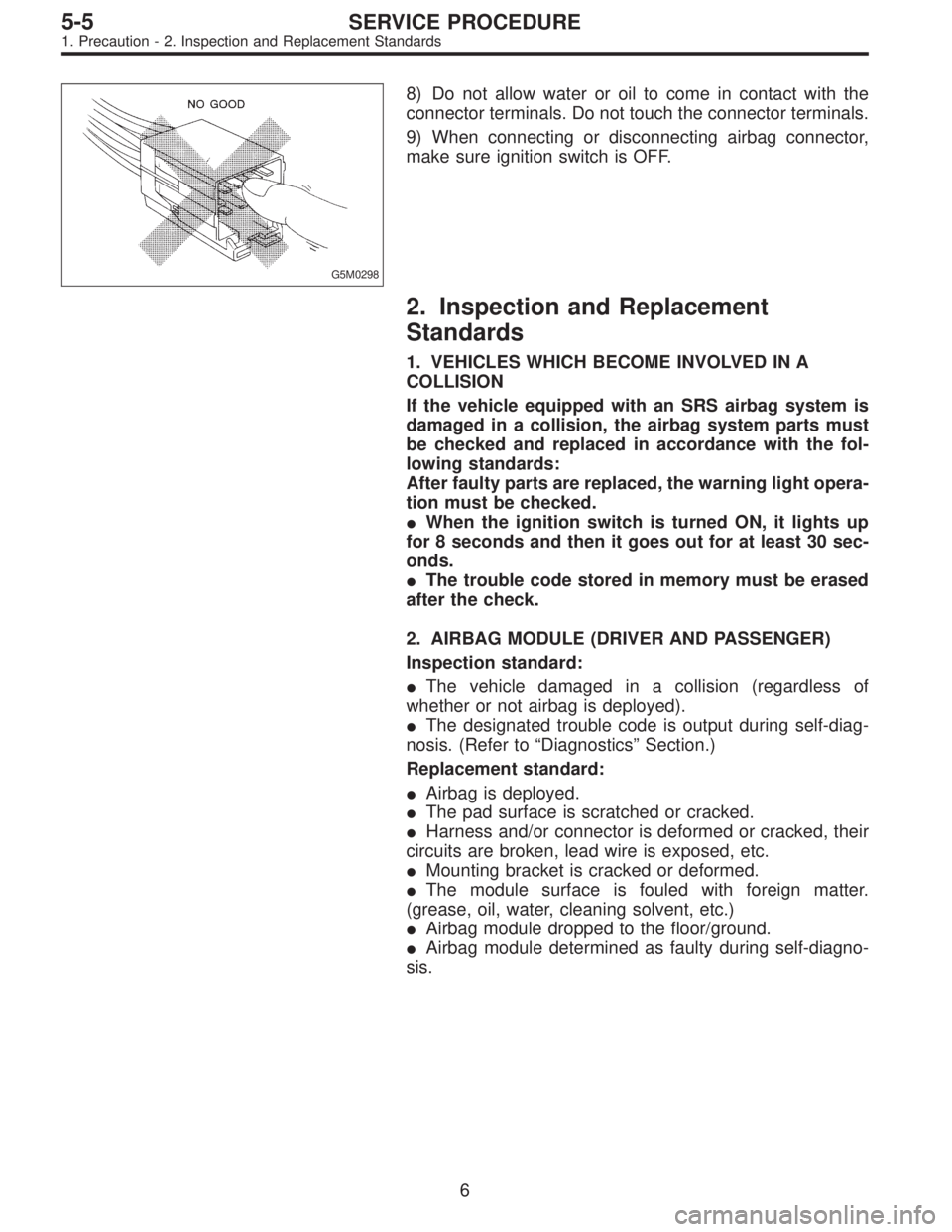
8) Do not allow water or oil to come in contact with the
connector terminals. Do not touch the connector terminals.
9) When connecting or disconnecting airbag connector,
make sure ignition switch is OFF.
2. Inspection and Replacement
Standards
1. VEHICLES WHICH BECOME INVOLVED IN A
COLLISION
If the vehicle equipped with an SRS airbag system is
damaged in a collision, the airbag system parts must
be checked and replaced in accordance with the fol-
lowing standards:
After faulty parts are replaced, the warning light opera-
tion must be checked.
�When the ignition switch is turned ON, it lights up
for 8 seconds and then it goes out for at least 30 sec-
onds.
�The trouble code stored in memory must be erased
after the check.
2. AIRBAG MODULE (DRIVER AND PASSENGER)
Inspection standard:
�The vehicle damaged in a collision (regardless of
whether or not airbag is deployed).
�The designated trouble code is output during self-diag-
nosis. (Refer to“Diagnostics”Section.)
Replacement standard:
�Airbag is deployed.
�The pad surface is scratched or cracked.
�Harness and/or connector is deformed or cracked, their
circuits are broken, lead wire is exposed, etc.
�Mounting bracket is cracked or deformed.
�The module surface is fouled with foreign matter.
(grease, oil, water, cleaning solvent, etc.)
�Airbag module dropped to the floor/ground.
�Airbag module determined as faulty during self-diagno-
sis.
6
5-5SERVICE PROCEDURE
1. Precaution - 2. Inspection and Replacement Standards
Page 1048 of 2248

G5M0298
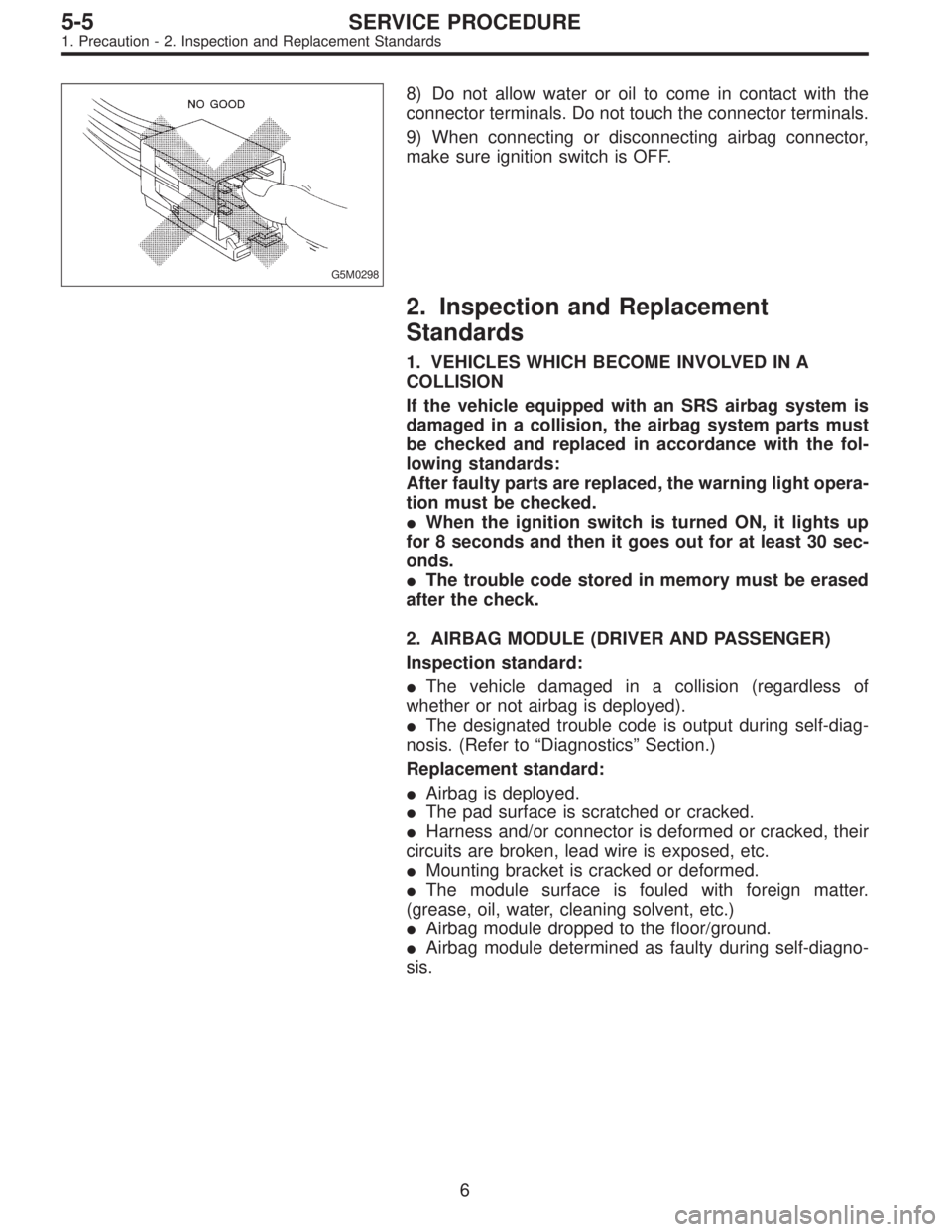
8) Do not allow water or oil to come in contact with the
connector terminals. Do not touch the connector terminals.
9) When connecting or disconnecting airbag connector,
make sure ignition switch is OFF.
2. Inspection and Replacement
Standards
1. VEHICLES WHICH BECOME INVOLVED IN A
COLLISION
If the vehicle equipped with an SRS airbag system is
damaged in a collision, the airbag system parts must
be checked and replaced in accordance with the fol-
lowing standards:
After faulty parts are replaced, the warning light opera-
tion must be checked.
�When the ignition switch is turned ON, it lights up
for 8 seconds and then it goes out for at least 30 sec-
onds.
�The trouble code stored in memory must be erased
after the check.
2. AIRBAG MODULE (DRIVER AND PASSENGER)
Inspection standard:
�The vehicle damaged in a collision (regardless of
whether or not airbag is deployed).
�The designated trouble code is output during self-diag-
nosis. (Refer to“Diagnostics”Section.)
Replacement standard:
�Airbag is deployed.
�The pad surface is scratched or cracked.
�Harness and/or connector is deformed or cracked, their
circuits are broken, lead wire is exposed, etc.
�Mounting bracket is cracked or deformed.
�The module surface is fouled with foreign matter.
(grease, oil, water, cleaning solvent, etc.)
�Airbag module dropped to the floor/ground.
�Airbag module determined as faulty during self-diagno-
sis.
6
5-5SERVICE PROCEDURE
1. Precaution - 2. Inspection and Replacement Standards
Page 1054 of 2248
A: REMOVAL
1. DRIVER SIDE
1) Set front wheels in straight ahead position.
2) Turn ignition switch off.
3) Disconnect ground cable from battery and wait for at
least 20 seconds before starting work.
G5M0307
4) Remove covers from both sides of steering wheel.
Using TORX®BIT T30 (Tamper resistant type), remove
four TORX®bolts.
G5M0308
5) Disconnect airbag and horn connectors on back of air-
bag module.
6) Refer to“CAUTION”for handling of a removed airbag
module.
2. PASSENGER SIDE
1) Remove instrument panel.
12
5-5SERVICE PROCEDURE
3. Airbag Module
Page 1055 of 2248

B5M0098
2) Remove four bolts and then carefully remove airbag
module.
3) Refer to“CAUTION”for handling of a removed airbag
module.
B: INSTALLATION
Installation is in reverse order of removal procedures.
Observe the following: Make sure that ignition switch is off.
CAUTION:
Do not allow harness and connectors to interfere or
get caught with other parts.
G5M0291
4. Front Sensor
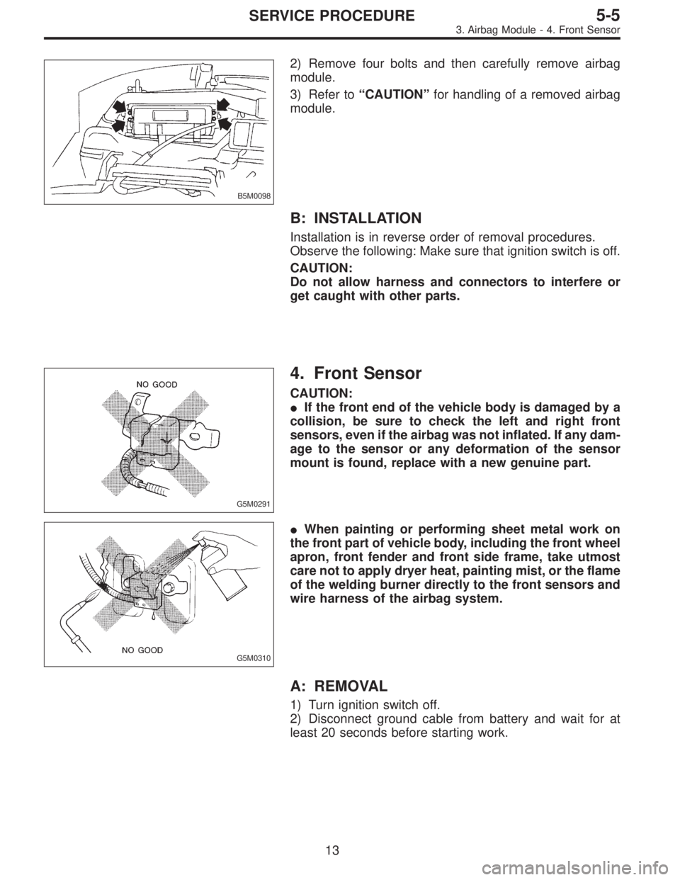
CAUTION:
�If the front end of the vehicle body is damaged by a
collision, be sure to check the left and right front
sensors, even if the airbag was not inflated. If any dam-
age to the sensor or any deformation of the sensor
mount is found, replace with a new genuine part.
G5M0310
�When painting or performing sheet metal work on
the front part of vehicle body, including the front wheel
apron, front fender and front side frame, take utmost
care not to apply dryer heat, painting mist, or the flame
of the welding burner directly to the front sensors and
wire harness of the airbag system.
A: REMOVAL
1) Turn ignition switch off.
2) Disconnect ground cable from battery and wait for at
least 20 seconds before starting work.
13
5-5SERVICE PROCEDURE
3. Airbag Module - 4. Front Sensor
Page 1056 of 2248

B5M0098
2) Remove four bolts and then carefully remove airbag
module.
3) Refer to“CAUTION”for handling of a removed airbag
module.
B: INSTALLATION
Installation is in reverse order of removal procedures.
Observe the following: Make sure that ignition switch is off.
CAUTION:
Do not allow harness and connectors to interfere or
get caught with other parts.
G5M0291
4. Front Sensor
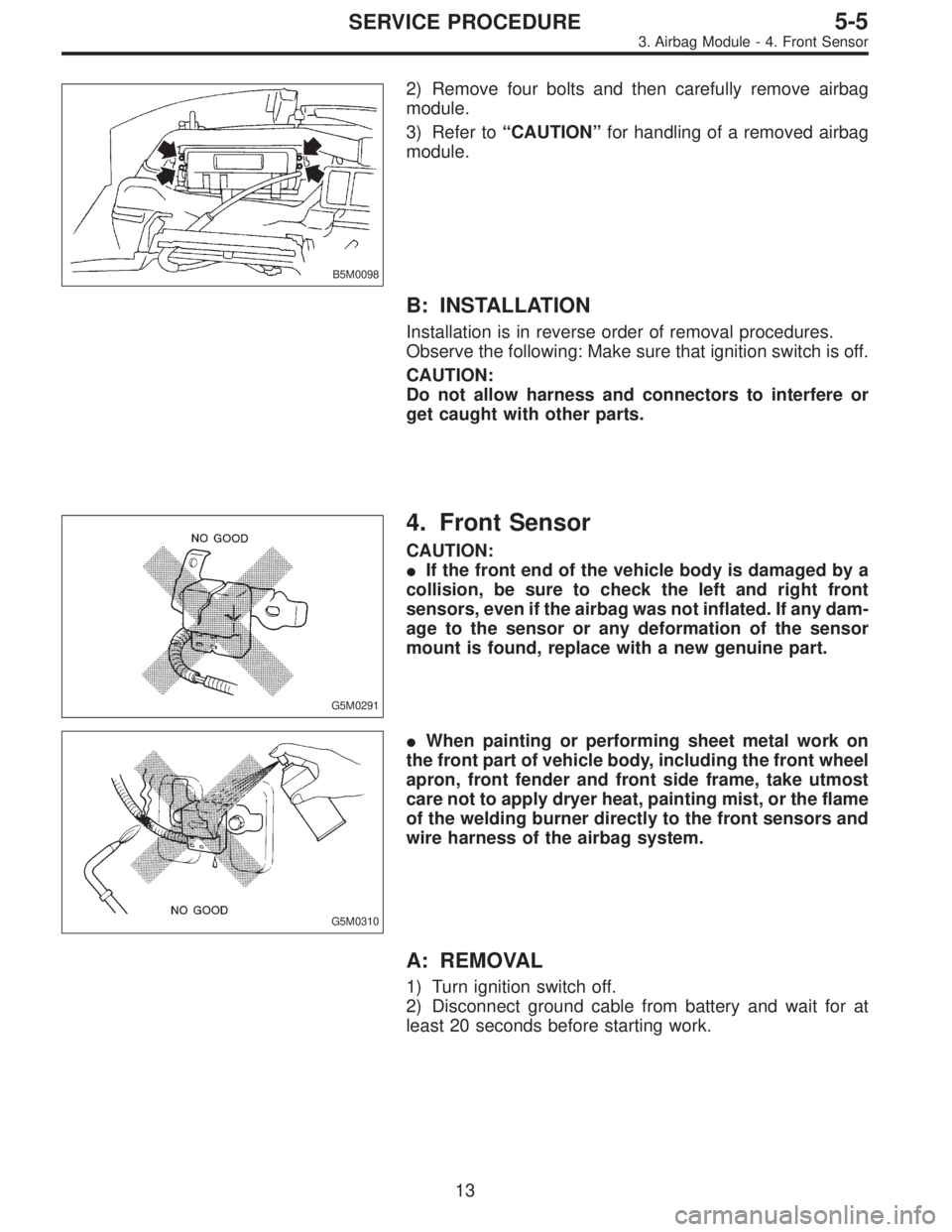
CAUTION:
�If the front end of the vehicle body is damaged by a
collision, be sure to check the left and right front
sensors, even if the airbag was not inflated. If any dam-
age to the sensor or any deformation of the sensor
mount is found, replace with a new genuine part.
G5M0310
�When painting or performing sheet metal work on
the front part of vehicle body, including the front wheel
apron, front fender and front side frame, take utmost
care not to apply dryer heat, painting mist, or the flame
of the welding burner directly to the front sensors and
wire harness of the airbag system.
A: REMOVAL
1) Turn ignition switch off.
2) Disconnect ground cable from battery and wait for at
least 20 seconds before starting work.
13
5-5SERVICE PROCEDURE
3. Airbag Module - 4. Front Sensor