Page 3 of 1701

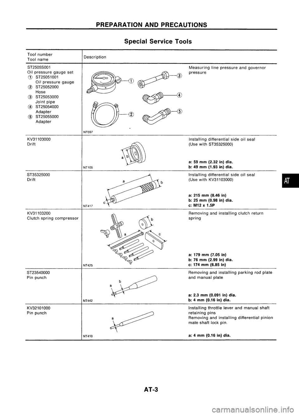
Toolnumber
Tool name
PREPARATION
ANDPRECAUTIONS
Special Service Tools
Description
8T25058001
Oil pressure gaugeset
G)
8T25051001
Oil pressure gauge
@ 8T25052000
Hose
@
8T25053000
Joint pipe
@
8T25054000
Adapter
@
8T25055000
Adapter Measuring
linepressure andgovernor
pressure
NT097
KV31103000
Drift
8T35325000 Drift
KV31103200
Clutch spring compressor
8T23540000 Pin punch
KV32101000
Pin punch
NT105
NT417
NT425
NT442
NT410
AT-3
Installing
differential sideoilseal
(Use with8T35325000)
a: 59 mm (2.32 in)dia.
b: 49 mm (1.93 in)dia.
Installing differential sideoilseal
(Use withKV31103000)
a: 215 mm (8.46 in)
b: 25 mm (0.98 in)dia.
c: M12 x1.5P
Removing andinstalling clutchreturn
spring
a: 179 mm (7.05 in)
b: 76 mm (2.99 in)dia.
c: 174 mm (6.85 in)
Removing andinstalling parkingrodplate
and manual plate
a: 2.3 mm (0.091 in)dia.
b: 4mm (0.16 in)dia.
Installing throttleleverandmanual shaft
retaining pins
Removing andinstalling differential pinion
mate shaft lockpin.
a: 4mm (0.16 in)dia.
•
Page 5 of 1701

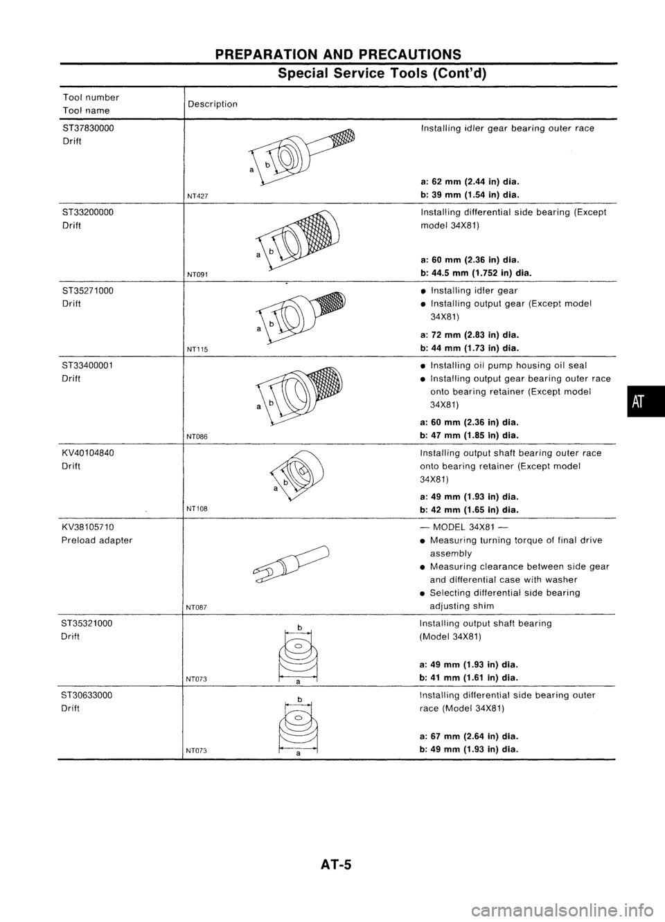
Toolnumber
Tool name
PREPARATION
ANDPRECAUTIONS
Special Service Tools(Cont'd)
Description
8T37830000 Drift
8T33200000 Drift
8T35271000 Drift
8T33400001
Drift
KV40104840
Drift
KV38105710
Preload adapter
8T35321000
Drift
ST30633000 Drift
NT427
NT091
NT115
NT086
NT108
NT087
NT073 NT073
AT-5
Installing
idlergear bearing outerrace
a: 62 mm (2.44 in)dia.
b: 39 mm (1.54 in)dia.
Installing differential sidebearing (Except
model 34X81)
a: 60 mm (2.36 in)dia.
b: 44.5 mm(1.752 in)dia.
• Installing idlergear
• Installing outputgear(Except model
34X81)
a: 72 mm (2.83 in)dia.
b: 44 mm (1.73 in)dia.
• Installing oilpump housing oilseal
• Installing outputgearbearing outerrace
onto bearing retainer (Exceptmodel •
34X81)
a: 60 mm (2.36 in)dia.
b: 47 mm (1.85 in)dia.
Installing outputshaftbearing outerrace
onto bearing retainer (Exceptmodel
34X81)
a: 49 mm (1.93 in)dia.
b: 42 mm (1.65 in)dia.
- MODEL 34X81-
• Measuring turningtorqueoffinal drive
assembly
• Measuring clearancebetweensidegear
and differential casewithwasher
• Selecting differential sidebearing
adjusting shim
Installing outputshaftbearing
(Model 34X81)
a: 49 mm (1.93 in)dia.
b: 41 mm (1.61 in)dia.
Installing differential sidebearing outer
race (Model 34X81)
a: 67 mm (2.64 in)dia.
b: 49 mm (1.93 in)dia.
Page 131 of 1701
REPAIRFORCOMPONENT PARTS
Band Servo Piston Assembly (Cont'd)
11. Install bandservo piston snapringtotransmission case.
SAT288D FinalDrive -Except Model34X81
I
L
Final gear
SEC.
381
OJ
\ Differentialcase
\ -Speedometer drivegear
~ Differential sidebearing
*
:
Select proper thickness.
SAT680DB
•
DISASSEMBL Y
1. Remove finalgear.
SAT311D
2.Press outdifferential sidebearings.
ST30021000
SAT681D AT-131
Page 133 of 1701
Pinionmateshaft
r= REPAIR
FORCOMPONENT PARTS
Final Drive -Except Model34X81(Cont'd)
ASSEMBLY
1. Install sidegears andside gear thrust washers indifferen-
tial case.
2. Install pinion mategears andpinion matethrust washers in
the differential casewhile rotating them.
• Apply ATF toall parts.
SAT318D
Both feeler gauges arethe
same thickness.
3.
Measure clearance betweensidegear anddifferential case
with washers.
Clearance betweensidegear anddifferential case
with washers:
0.1 -0.2 mm (0.004 -0.008 in)
SAT321D •
If
not within specification, adjustclearance bychanging •
thickness ofside gear thrust washers.
Side gear thrust washer:
Refer to50S, AT-170.
KV32101000
SAT077E
4.
Install lockpin.
• Make surethatlock pinisflush withcase.
5. Install speedometer drivegearondifferential case.
• Align projection ofspeedometer drivegearwithgroove of
differential
case.
AT-133
Page 251 of 1701
EXTERIOR
•
SBT069
SBT070
Back doorwindow molding
Bonding
portion
@
Trunk lidweatherstrip
SEC. 843
@ Back doorsidesealing rubber
SEC. 909
@ Back doorwindow molding
SEC. 900
SBT06B
Heat
gun
•
;Double-faced adhesivetape
~~~~ ..
-----~
.
~.: ..
~-o
~.
"----'
-.-/
'-
3-door
@J
Side guard molding
SEC. 766
4-door and5-door
• With avehicle coatedwithHard Clear Coat,
use double-faced 3Madhesive tapeProduct
No. 4210 orequivalent, afterpriming with3M
primer Product No.N-200 orC-100 orequiva-
lent.
@
Rear window uppermolding andside
molding
Basically thesame aswindshield uppermolding.
Refer to@ Windshield uppermolding.
@ Rear window lowermolding
Mounted withscrews.
Removal:Removemolding
by
cutting around itsperimeter.
Installation: Referto"Back doorwindow."
MBF13BAA
8T-31
Page 399 of 1701
BATTERY
How toHandle Battery(Cont'd)
2. Convert intospecific gravityat20°C (68°F).
Example:
• When electrolyte temperature is35°C (95°F) andspecific
gravity ofelectrolyte is1.230, converted specificgravityat
20°C (68°F) is1.240.
• When electrolyte temperature isO°C (32°F) andspecific
gravity ofelectrolyte is1.210, converted specificgravityat
20°C (68°F) is1.196.
Converted specificgravity
1.30
Q)
1.28
:;
~
1.26
Q)
0-
E
1.24
l!l
Q)
>.
1.22
e
0
Q)
1.20
a;
<;;
>,
1.18
=5
'"
0,
1.16
.g
U
1.14
Q)
0-
00
1.12
1.10 -30-20
(-22) (-4)-10
01020 30
(14) (32)(50) (68) (86)
Electrolyte temperature °C
(OF)
EL-27
40
50
(104) (122)
SELOO7Z
•
Page 401 of 1701
CAPACITYTEST BATTERY
Battery TestandCharging Chart(Cont'd)
• Check battery typeanddetermine thespecified current
using thefollowing table.
Fig. 1DISCHARGING CURRENT
(Load Tester)
~m o~
Type
Current
(A)
28B19R(L) 90
34B19R(L) 99
46B24R(L) 135
55B24R(L) 135
50D23R(L) 150
55D23R(L) 180
65D26R(L) 195
80D26R(L) 195
75D31R(L) 210
95D31R(L) 240
115D31R(L) 240
95E41R(L) 300
130E41R(L) 330
Test
using loadtester.
OK NG
Read
loadtester voltage
when specified discharging
current (RefertoFig~ 1.)
flows through batteryfor15
seconds.
Above 9.6 Below9.6
volts volts
Ready foruse Gotonext
step.
Chart
II
OK NG
Follow
manufacturer's
instructions tocheck and
determine ifbattery isser-
viceable,
Ready foruse Gotonext
step.
SEL008Z
•
EL-29
Page 499 of 1701
METERANDGAUGES
Combination Meter
WITH TACHOMETER
Gasolineengine
Diesel engine
o
~
~
RESISTOR
(Gasoline engine)
~
DIODE
\*"
\~\=S=I
=======~
,-,------
,
\
30 14
Gasoline
engine
Diesel engine
For Australia
Except forAustralia
@
@
@D
@
o
1 8
2 9
310
411
1
12
13
514
615
716
6 27 34373628 1210
@
•
a:
@J
0
~ u.
@
a:
@
()
u. LlJ
is
a:
0
LlJ
~
I
~ --J
f:J
~ --J
0
Cl
(J)
LlJ
0
(J)
0
a:
co
::>
--J
LlJ
Z
0
Cl
0
co
u.
CD
~
co
0
1=
@~
a:::J
LlJu.
f:J
U::~
z
z z
a:
0 0 0
LlJ
I-
~ ~ ~ LlJ
I I
~
~
Z Z Z
--J
a:
()
0
~ ~ ~
ZZ
0
I
::J ::J
::J
a:
a: --J
()
--J --J --J
::J::J
()
~
:::! :::!
:::!
l-
I-
~
>---
()
0
--J
()
5
29
17
131618
1938 15 32
4140 4239 26
@
2
4 7
@
8
33 31 3
HEL065
EL-127