Page 1336 of 1701
SERVICEOATAAND SPECIFICATIONS (SOS)
Inspection andAdjustment (Cont'd)
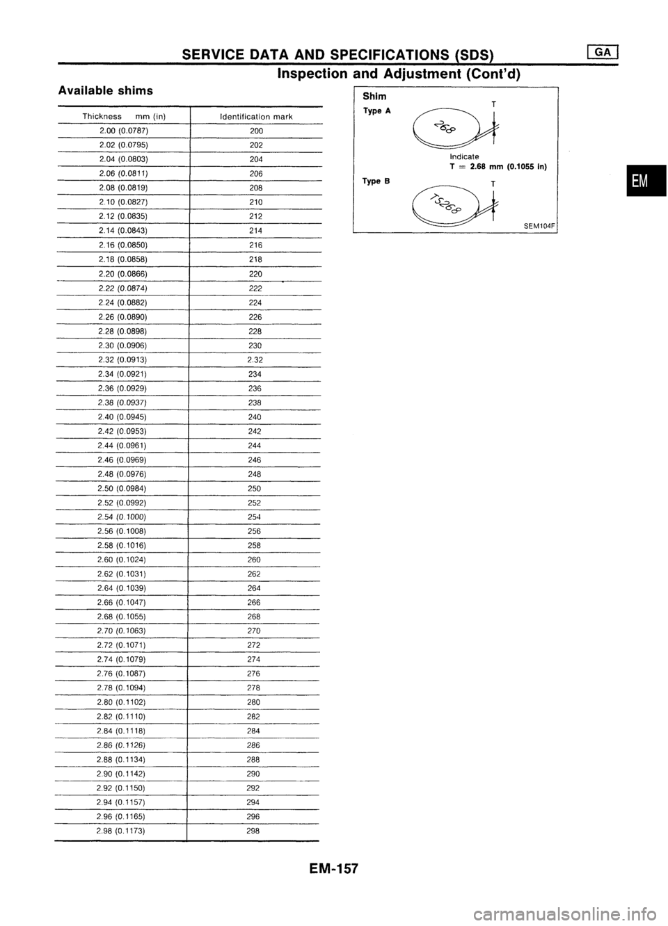
Indicate
T
=
2.68
mm
(0.1055 In)
Available
shims
Thickness mm(in)
Identificationmark
2.00 (0.0787)
200
2.02 (0.0795)
202
2.04 (0.0803)
204
2.06 (0.0811)
206
2.08 (0.0819)
208
210 (0.0827)
210
2.12 (00835)
212
2.14 (0.0843)
214
216 (0.0850)
216
2.18 (0.0858) 218
2.20 (0.0866) 220
2.22 (00874) 222
224 (00882)
224
2.26 (0.0890)
226
2.28 (0.0898) 228
2.30 (0.0906)
230
2.32 (0.0913) 2.32
2.34 (0.0921)
234
2.36 (0.0929)
236
2.38 (0.0937)
238
240 (0.0945)
240
2.42 (0.0953) 242
2.44 (0.0961) 244
2.46 (0.0969)
246
2.48 (0.0976) 248
2.50 (00984)
250
2.52 (0.0992) 252
2.54 (0.1000)
254
2.56 (01008) 256
2.58 (0.1016) 258
2.60 (0.1024)
260
262 (0.1031) 262
2.64 (0.1039) 264
2.66 (0.1047)
266
2.68 (0.1055) 268
2.70 (0.1063) 270
2.72 (0.1071) 272
2.74 (0.1079) 274
2.76 (0.1087) 276
278 (0.1094)
278
2.80 (01102) 280
282 (01110) 282
284 (0.1118)
284
286 (0.1126) 286
2.88 (01134)
288
290 (0.1142) 290
2.92 (0.1150) 292
294 (0.1157)
294
296 (0.1165) 296
2.98 (0.1173) 298Shim
Type A
Type B
SEM104F
•
EM-157
Page 1347 of 1701
SERVICEDATAANDSPECIFICATIONS (SOS)
Inspection andAdjustment (Cont'd)
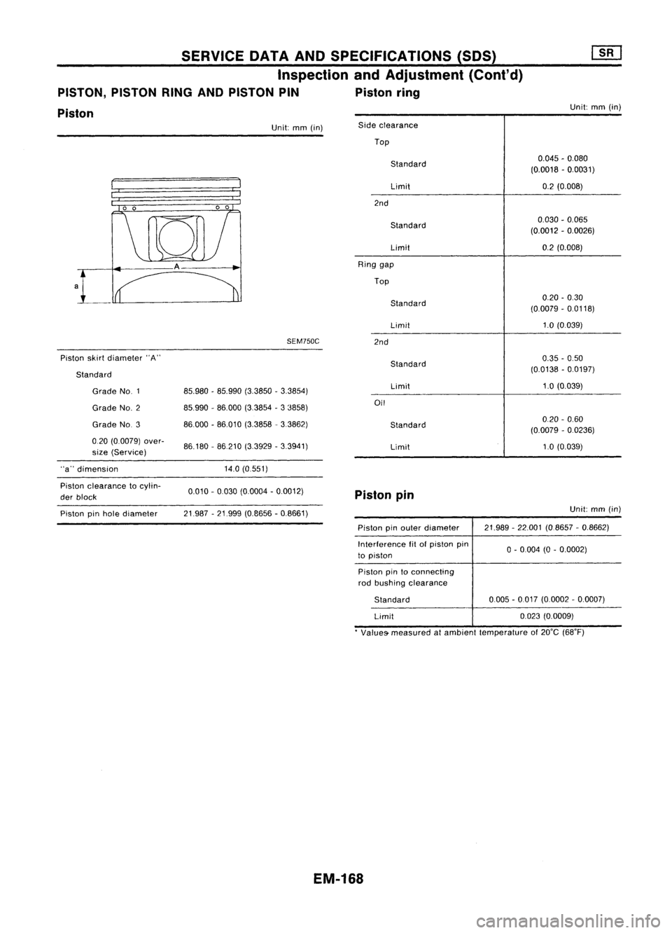
PISTON, PISTONRINGANDPISTON PIN Pistonring
Piston
Unit:
mm(in)
SEM750C
Piston skirtdiameter "A" Unit:
mm(in)
0.045-0.080
(0.0018 -0.0031)
0.2 (0.008)
020 -0.60
(0.0079 -0.0236)
1.0 (0.039)
0.030
-0.065
(0.0012 -0.0026)
0.2 (0.008)
0.20 -0.30
(0.0079 -0.0118)
1.0 (0.039)
0.35 -0.50
(0.0138 -0.0197)
1.0 (0.039)
Limit
Side
clearance
Top
Standard
Limit
2nd
Standard
Limit
Ring gap
Top
Standard
Limit
2nd
Standard
Limit
Oil
Standard
86.180 -86210 (3.3929 -3.3941)
85.980
-85.990 (3.3850 -3.3854)
85.990 -86.000 (3.3854 -3 3858)
86000 -86.010 (3.3858. 3.3862)
Grade NO.3
Grade
NO.1
Grade NO.2
020 (0.0079) over-
size (Service)
Standard
"a" dimension 14.0(0.551)
Piston clearance tocylin-
der block 0.010
-0.030 (0.0004 -0.0012)
Pistonpin
Piston pinhole diameter 21.987
-21.999 (0.8656 -0.8661) Unit:
mm(in)
Piston pinouter diameter
Interference fitofpiston pin
to piston 21.989
-22.001 (08657 -0,8662)
o -
0004 (0-0,0002)
Piston pintoconnecting
rod bushing clearance
Standard
Limit 0005
-0.017 (0,0002 -0,0007)
0,023 (0,0009)
• Values- measured atambient temperature of20°C (68°F)
EM-1G8
Page 1405 of 1701
PRECAUTIONSANDPREPARATION
Precautions forWorking withHFC-134a (R-134a)
WARNING:
• CFC-12 (R-12)refrigerant andHFC-134a (R-134a)refrigerant arenotcompatible. Theserefrigerants
must never bemixed, eveninthe smallest amounts. Ifthe refrigerants aremixed, compressor fail-
ure islikely tooccur .
• Use only specified lubricantforthe HFC-134a (R-134a)
A/C
system andHFC-134a (R-134a)compo-
nents. Iflubricant otherthanthatspecified isused, compressor failureislikely tooccur .
• The specified HFC-134a (R-134a)lubricant rapidlyabsorbs moisture fromtheatmosphere. Thefol-
lowing handling precautions mustbeobserved:
a: When removing refrigerant components fromavehicle, immediately cap(seal) thecomponent
to minimize theentry ofmoisture fromtheatmosphere.
b: When installing refrigerant components toavehicle, donot remove thecaps (unseal) untiljust
before connecting thecomponents. Connectallrefrigerant loopcomponents asquickly aspos-
sible tominimize theentry ofmoisture intosystem.
c: Only usethespecified lubricantfr.omasealed container. Immediately resealcontainers of
lubricant. Withoutpropersealing, lubricant willbecome moisture saturated andshould notbe
used.
d: Avoid breathing
A/C
refrigerant andlubricant vaporormist. Exposure mayirritate eyes,nose
and throat. Remove R-134afromthe
A/C
system, usingcertified serviceequipment meeting
requirements ofSAE J2210 (R-134a recycling eqUipment), orJ2209 (R-134a recovery equipment).
If accidental systemdischarge occurs,ventilate workareabefore resuming service.Additional
health andsafety information maybeobtained fromrefrigerant andlubricant manufacturers.
e: Do not allow lubricant (Nissan
A/C
System OilType S)tocome incontact withstyrofoam parts.
Damage mayresult.
GeneralRefrigerant Precautions
WARNING:
• Donot release refrigerant intotheair. Use approved recoverylrecycling equipmenttocapture the
refrigerant everytimeanair conditioning systemisdischarged.
• Always weareyeand hand protection (gogglesandgloves) whenworking withanyrefrigerant or
air conditioning system.
• Donot store orheat refrigerant containersabove52°C(125°F).
• Donot heat arefrigerant containerwithanopen flame; ifcontainer warmingisrequired, placethe
bottom ofthe container inawarm pailofwater.
• Donot intentionally drop,puncture, orincinerate refrigerant containers.
• Keep refrigerant awayfromopen flames: poisonous gaswillbeproduced ifrefrigerant burns.
• Refrigerant willdisplace oxygen,therefore becertain towork inwell ventilated areastoprevent
suffocation.
• Donot introduce compressed airtoany refrigerant containerorrefrigerant component.
HA-3
•
Page 1544 of 1701
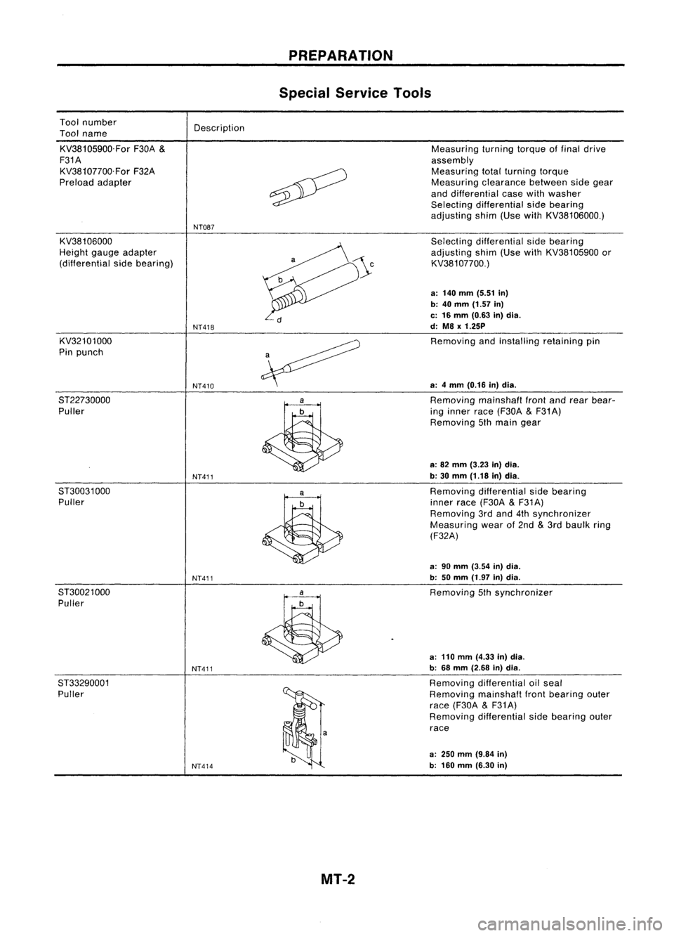
Toolnumber
Tool name
KV38105900.For F30A
&
F31A KV38107700.For F32A
Preload adapter Description
NT087 PREPARATION
Special Service Tools
Measuring turningtorqueoffinal drive
assembly Measuring totalturning torque
Measuring clearancebetweensidegear
and differential casewithwasher
Selecting differential sidebearing
adjusting shim(UsewithKV38106000.)
KV38106000
Height gaugeadapter
(differential sidebearing)
KV32101000
Pin punch
8T22730000 Puller
8T30031 000
Puller
8T30021 000
Puller
ST33290001 Puller
NT418
NT410
NT411
NT411
NT411
NT414
Selecting
differential sidebearing
adjusting shim(UsewithKV38105900 or
KV381 07700.)
a: 140 mm (5.51 in)
b: 40
mm
(1.57
in)
c: 16 mm (0.63 in)dia.
d: M8
x
1.25P
Removing andinstalling retainingpin
a: 4mm (0.16 in)dia.
Removing mainshafl
front
andrear bear-
ing inner race(F30A
&
F31 A)
Removing 5thmain gear
a: 82 mm (3.23 in)dia.
b: 30 mm (1.18 in)dia.
Removing differential sidebearing
inner race(F30A
&
F31A)
Removing 3rdand 4thsynchronizer
Measuring wearof2nd
&
3rd baulk ring
(F32A)
a: 90 mm (3.54 in)dia.
b: 50mm (1.97 in)dia.
Removing 5thsynchronizer
a: 110 mm (4.33 in)dia.
b: 68 mm (2.68 in)dia.
Removing differential oilseal
Removing mainshaflfrontbearing outer
race (F30A
&
F31A)
Removing differential sidebearing outer
race
a:
250
mm
(9.84
in)
b: 160 mm (6.30 in)
MT-2
Page 1545 of 1701
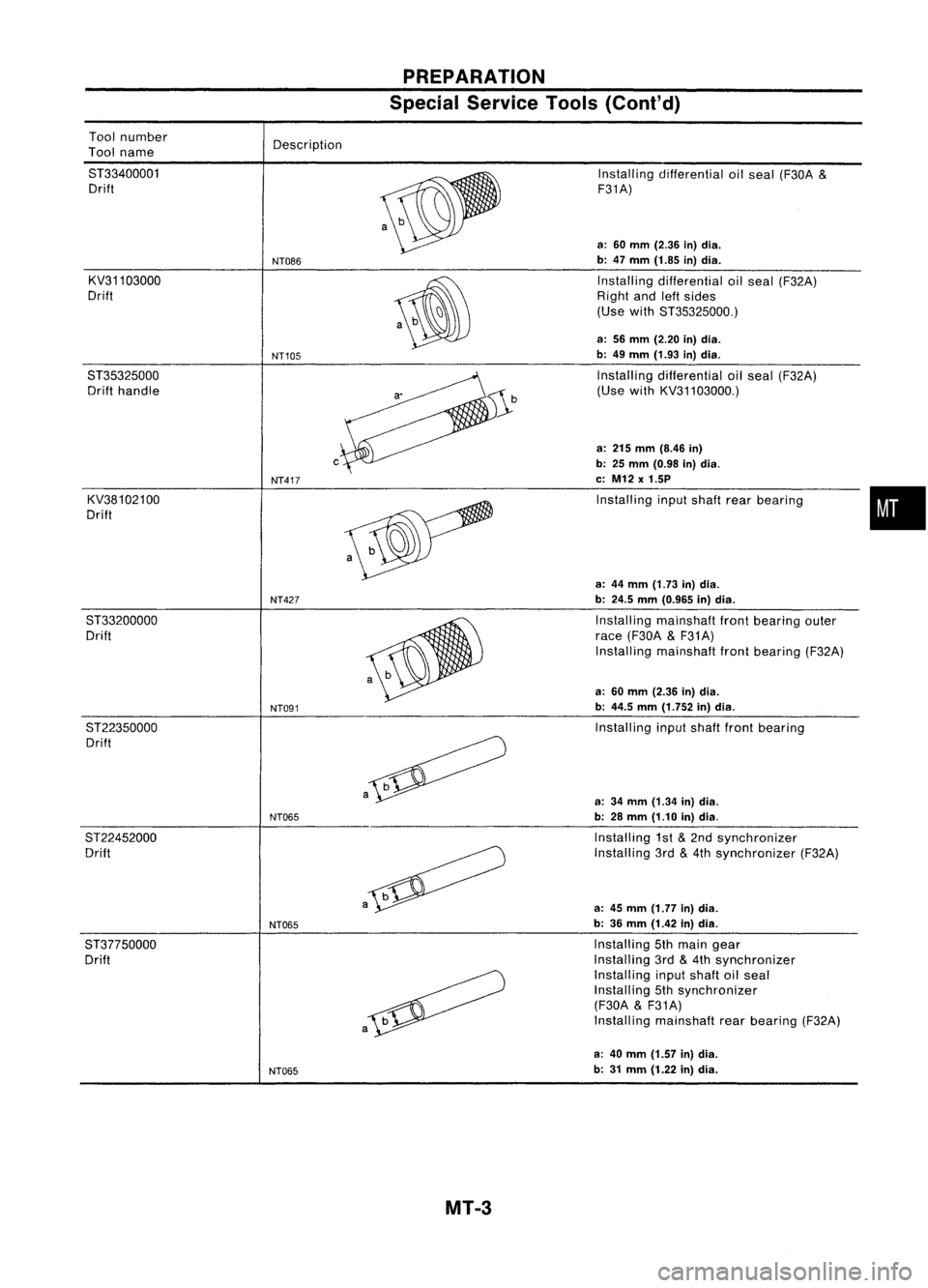
PREPARATION
Special Service Tools(Coni'd)
a-
Tool
number
Tool name
ST33400001 Drift
KV31103000
Drift
ST35325000 Drift handle
KV38102100
Drift Description
NT086
NT105
c
NT417
Installing
differential oilseal (F30A
&
F31A)
a: 60 mm (2.36 in)dia.
b: 47 mm (1.85 in)dia.
Installing differential oilseal (F32A)
Right andleftsides
(Use withST35325000.)
a: 56 mm (2.20 in)dia.
b: 49 mm (1.93 in)dia.
Installing differential oilseal (F32A)
(Use withKV31103000.)
a: 215 mm (8.46 in)
b: 25 mm (0.98 in)dia.
c: M12 x1.5P
Installing inputshaft rearbearing
•
a: 44 mm (1.73 in)dia.
NT427
b:24.5 mm(0.965 in)dia.
ST33200000 Installingmainshaft frontbearing outer
Drift race(F30A
&
F31A)
Installing mainshaft frontbearing (F32A)
a: 60 mm (2.36 in)dia.
NT091
b:
44.5 mm(1.752 in)dia.
ST22350000 Installinginputshaft frontbearing
Drift
a
a:34 mm (1.34 in)dia.
NT065
b:28 mm (1.10 in)dia.
ST22452000 Installing1st
&
2nd synchronizer
Drift Installing3rd
&
4th synchronizer (F32A)
a
a:45 mm (1.77 in)dia.
NT065
b:
36 mm (1.42 in)dia.
ST37750000 Installing5thmain gear
Drift Installing
3rd
&
4th synchronizer
Installing inputshaft oilseal
Installing 5thsynchronizer
(F30A
&
F31A)
a
Install
ingmainshaft rearbearing (F32A)
a: 40 mm (1.57 in)dia.
NT065
b:
31 mm (1.22 in)dia.
MT-3
Page 1546 of 1701
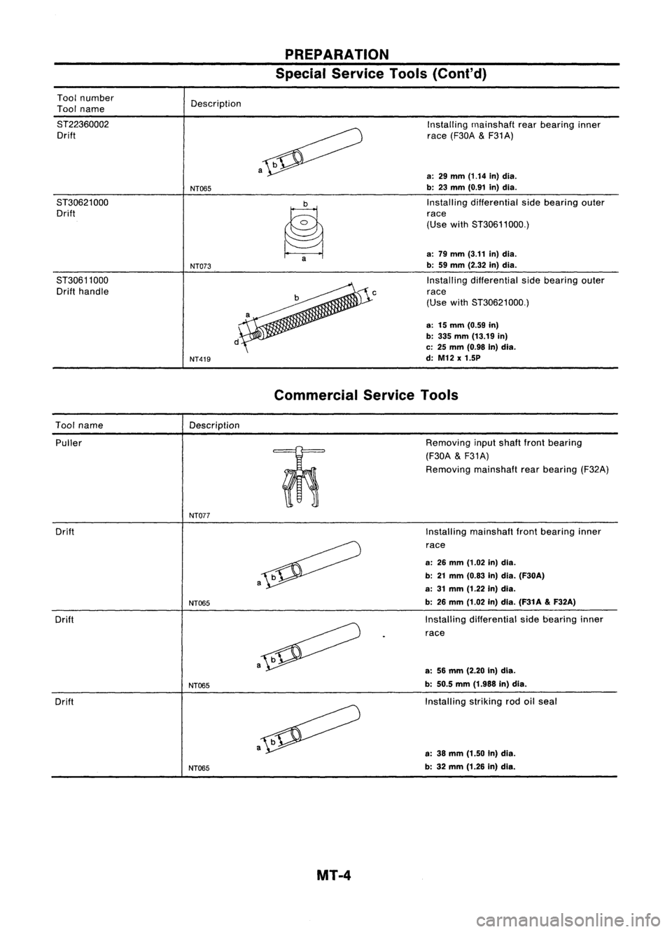
PREPARATION
Special Service Tools(Coni'd)
Tool number
Tool name
ST22360002 Drift
ST30621000 Drift
ST30611000 Drift handle Description
NT065
NT073
NT419 a
~a
Installing
rnainshaft rearbearing inner
race (F30A
&
F31A)
a:
29
mm
(1.14
in)dia.
b: 23 mm (0.91 in)dia.
Installing differential sidebearing outer
race
(Use withST30611000.)
a: 79 mm (3.11 in)dia.
b: 59mm (2.32 in)dia.
Installing differential sidebearing outer
race
(Use withST30621000.)
a: 15mm (0.59 in)
b: 335 mm (13.19 in)
c: 25 mm (0.98 In)dia.
d: M12 x1.5P
Commercial ServiceTools
Tool name
Description
Puller
m:
o
0
NT077
Drift
Drift
Drift
NT065
NT065
NT065 a
Removing
inputshaft frontbearing
(F30A
&
F31A)
Removing mainshaftrearbearing (F32A)
Installing mainshaft frontbearing inner
race
a: 26mm (1.02 in)dia.
b: 21mm (0.83 in)dia. (F30A)
a: 31mm (1.22 in)dia.
b: 26 mm (1.02 in)dia. (F31A
&
F32A)
Installing differential sidebearing inner
race
a: 56mm (2.20 In)dia.
b: 50.5 mm(1.988 in)dia.
Installing strikingrodoilseal
a: 38 mm (1.50 In)dia.
b: 32 mm (1.26 in)dla.
MT-4
Page 1557 of 1701
DISASSEMBLY RS5F30A
&
RS5F31 A
SMT648AA
KV32101000
SMT599AA
SMT583
/ Reverse checkplug
~ "Reverse checkspring
S/
V
Check ball(Large)
"--_Check ball(Small)
SMT584
SMT585
5.
Remove oilpocket, shiftcheck ball,shift check spring and
check ballplug.
6. Drive retaining pinout ofstriking lever,thenremove strik-
ing rod, striking leverandstriking interlock.
• Select aposition whereretaining pindoes notinterfere with
. clutch housing whenremoving retainingpin.
• Becareful nottodamage oilseal lip,when removing strik-
ing rod. Ifnecessary, tapeedges ofstriking rod.
7. Remove reversecheckplug,thendetach reverse check
spring andcheck balls,
8. Remove checksleeve assembly.
MT-15
•