Page 1567 of 1701
1/
REPAIR
FORCOMPONENT PARTS
I
RS5F30A
&
RS5F31A
I
Final Drive (Cont'd)
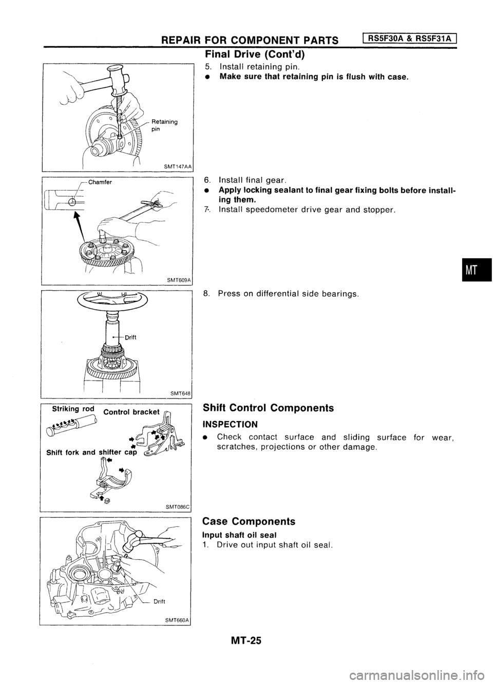
5. Install retaining pin.
• Make surethatretaining pinisflush withcase.
Retaining
pin
SMT147AA
6.Install finalgear.
• Apply locking sealant tofinal gear fixing boltsbefore install-
ing them.
7-. Install speedometer drivegearandstopper .
SMT609A
•
;?
Control
b~'Ck:t ,
.. ~-t'
If
0
Shift forkandshifter cap
",0
~ SMT086C
8.
Press ondifferential sidebearings.
Shift Control Components
INSPECTION
• Check contact surface andsliding surface forwear,
scratches, projections orother damage.
Case Components
Input shaftoilseal
1. Drive outinput shaftoilseal.
MT-25
Page 1569 of 1701
Toward
oil pocket
REPAIR
FORCOMPONENT PARTS
I
RS5F30A
&
RS5F31A
I
Case Components (Cont'd)
Mainshaft frontbearing outerraceandoilchannel
1. Remove mainshaft frontbearing outerrace.
2. Remove oilchannel.
SMT636-A
3.Install oilchannel.
• Ensure theoilgroove facestheoilpocket.
SMT595
•
4. Install mainshaft frontbearing outerrace.
Mainshaft rearbearing outerrace
• Refer to"Differential SideBearing Preload", MT-29.
Differential sidebearing outerrace
• Refer to"Mainshaft BearingPreload", MT-28.
MT-27
Page 1570 of 1701
ADJUSTMENT
I
RS5F30A
&
RS5F31 A
I
SMT646-A
I"
KV38106000
SMT454-ADifferential
SideBearing Preload
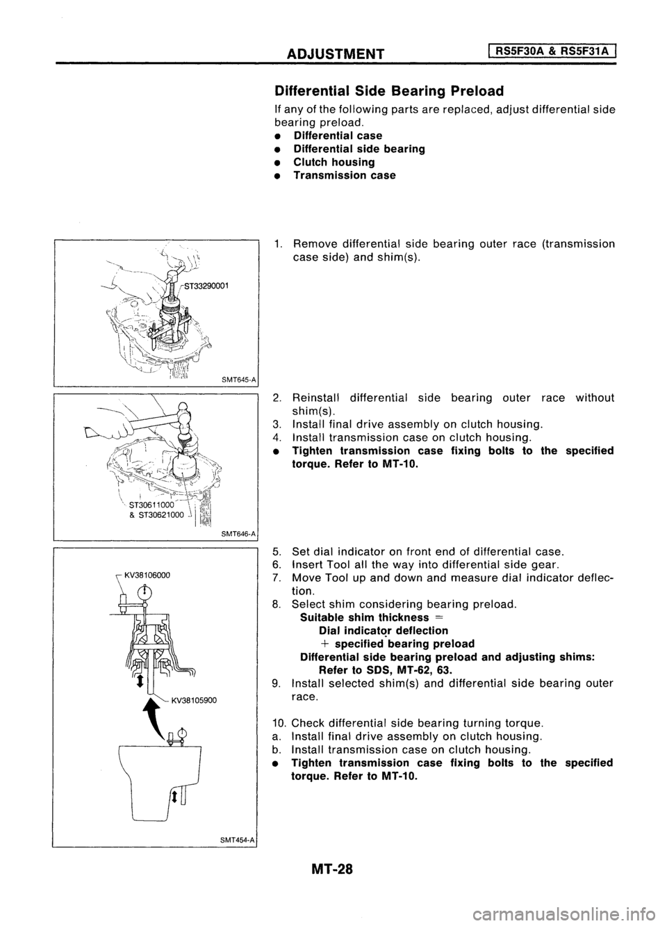
If any ofthe following partsarereplaced, adjustdifferential side
bearing preload.
• Differential case
• Differential sidebearing
• Clutch housing
• Transmission case
1. Remove differential sidebearing outerrace(transmission
case side) andshim(s).
2. Reinstall differential sidebearing outerracewithout
shim(s).
3. Install finaldrive assembly onclutch housing.
4. Install transmission caseonclutch housing.
• Tighten transmission casefixing boltstothe specified
torque. RefertoMT-10.
5. Set dial indicator onfront endofdifferential case.
6. Insert Toolallthe way intodifferential sidegear.
7. Move Toolupand down andmeasure dialindicator deflec-
tion.
8. Select shimconsidering bearingpreload.
Suitable shimthickness =
Dial
indicat~r
deflection
+ specified bearingpreload
Differential sidebearing preload andadjusting shims:
Refer to50S, MT-62, 63.
9. Install selected shim(s)anddifferential sidebearing outer
race.
10. Check differential sidebearing turningtorque.
a. Install finaldrive assembly onclutch housing.
b. Install transmission caseonclutch housing.
• Tighten transmission casefixing boltstothe specified
torque. RefertoMT-10.
MT-28
Page 1571 of 1701
~casecover"U--0-ring
~spacer
Mainshaft rearbearing ~ Mainshaft
outer race ~
0
bearing
- \ adjusting
shim
I ~--
SMT613AA
SMT599 ADJUSTMENT
I
RS5F30A
&
RS5F31A
I
Differential SideBearing Preload(Cont'd)
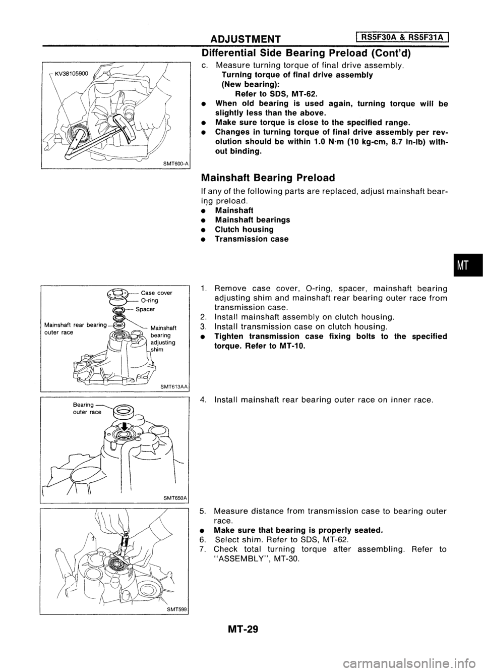
c. Measure turningtorqueoffinal drive assembly.
Turning torqueoffinal drive assembly
(New bearing):
Refer toSOS, MT-62.
• When oldbearing isused again, turning torquewillbe
slightly lessthan theabove.
• Make suretorque isclose tothe specified range.
• Changes inturning torqueoffinal drive assembly perrev-
olution shouldbewithin 1.0N'm (10kg-em, 8.7in-Ib) with-
out binding.
Mainshaft BearingPreload
If any ofthe following partsarereplaced, adjustmainshaft bear-
il}g preload.
• Mainshaft
• Mainshaft bearings
• Clutch housing
• Transmission case
1. Remove casecover, O-ring, spacer, mainshaft bearing
adjusting shimandmainshaft rearbearing outerracefrom
transmission case.
2. Install mainshaft assemblyonclutch housing.
3. Install transmission caseonclutch housing.
• Tighten transmission casefixing boltstothe specified
torque. RefertoMT-10.
4. Install mainshaft rearbearing outerraceoninner race.
5. Measure distancefromtransmission casetobearing outer
race.
• Make surethatbearing isproperly seated.
6. Select shim.RefertoSDS, MT-62.
7. Check totalturning torqueafterassembling. Referto
"ASSEMBLY", MT-30.
MT-29
•
Page 1575 of 1701

~.L'
J
(15,'
~
3.7•5.0 (0.38 •0.51, 33.0-44.3)
CD ~
Mating surface to
transmission case~
I")
MAJOROVERHAUL
I
RS5F32A
I
Case Components
•
\
\L~
6.3.8.3
(0.64 -0.85, 55.6-73.8)
~.L'
J
(15,'
~
3.7•5.0 (0.38 •0.51, 33.0-44.3)
CD ~
Mating surface to
transmission case~
I
;1
~3J
1J2»~
o//~
d~~~
!-~~
i~=1D.
(]?
CID.:.
m
Seal lip \
\
.
~)~
//\
1~
~'
(fl)
to.J
20-29 \
- (2.0-3.0, 14-22)
~ Thread ofbolt
@
~
Mating surface to
SEC.320
@~
10.20 (1.0-2.0, 87-174)
W ~
Mating surface to ~Thread ofbolt
"""mi"ioo '""
\1:.0
1 ~ /',
. WO,,~., .,.~
~~~> '\
t,,~~~~
o
I:::t:\ ~___-- __~
j)\~
~i)~/
(ro\~\~)
. ------ ~~,/ ~Q~
I
f""\
~~~ ..~ Q{
t~A
26-30 (2.7 -3.1, 20-22)
!13i
~ 25_34 ~N.m(kg-m, In-Ib\
(2.5 -3.5, 18-25)
A
N.m(kg-m, ft-Ib)
~ Thread ofbolt ~.Apply recommended sealant
(Nissan genuine part:KP610-00250) orequivalent
12)~.
m
Seal lip ~
,.1..',
Apply locking sealant
* :
Select proper thickness.
-tI .
Pay attention toits direction,
*
@~Mating
SMT751C
G)
Clutch housing
@
Reverse idlershaft
@
Input shaftoilseal
@
Oilpocket
@
Bearing retainer
@
Filler plug
(J)
Airbreather
@
Welch plug
(9)
O-ring
@
Case cover
CfD
Back-up lampswitch
@
Differential oilseal
@
Drain plug
@
Transmission case
@
Oilgutter
@
Oilchannel
@
Bearing retainer
@l
Striking rodoilseal
QID
Boot
@
Neutral position switch
@
Differential oilseal
@
O-ring
@
Speedometer pinionassembly
MT-33
Page 1576 of 1701
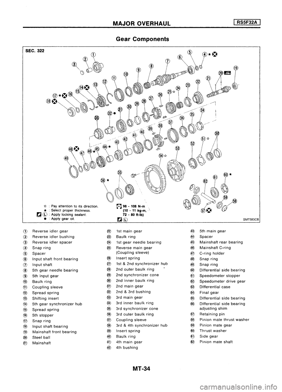
SEC.322
u:Pay attention toits direction.
* :
Select proper thickness.
~ ~) :Apply locking sealant.
• :Apply gearoil.
CD
Reverse idlergear
@
Reverse idlerbushing
@
Reverse idlerspacer
@
Snap ring
@
Spacer
@
Input shaftfrontbearing
(j) Input shaft
@
5thgear needle bearing
@
5thinput gear
@)
Baulk ring
@
Coupling sleeve
@
Spread spring
@
Shifting insert
@
5thgear synchronizer hub
@
Spread spring
@l
5thstopper
@
Snap ring
@
Input shaftbearing
@l
Mainshaft frontbearing
@)
Steel ball
@
Mainshaft
MAJOR
OVERHAUL
Gear Components
@
1stmain gear
@
Baulk ring
@
1stgear needle bearing
@
Reverse maingear
(Coupling sleeve)
@
Insert spring
@
1st
&
2nd synchronizer hub
@
2ndouter baulk ring
@
2ndsynchronizer cone
@
2ndinner baulk ring
@
2ndmain gear
@
2nd
&
3rd bushing
@
3rdmain gear
@
3rdinner baulk ring
@
3rdsynchronizer cone
@ID
3rdouter baulk ring
@
Coupling sleeve
@
3rd
&
4th synchronizer hub
@
Insert spring
@
Baulk ring
@".!J
4thmain gear
@
4thbushing
MT-34
I
RS5F32A
I
SMT593CB
@
5thmain gear
I[~
Spacer
~~ Mainshaft rearbearing
~ID
Mainshaft C-ring
@
C-ring holder
@
Snap ring
@
Snap ring
@
Differential sidebearing
@
Speedometer stopper
@
Speedometer drivegear
@
Differential case
{4)
Final gear
@
Differential sidebearing
@
Differential sidebearing
adjusting shim
@
Retaining pin
@
Pinion matethrust washer
@
Pinion mategear
~O)
Thrust washer
@
Side gear
@
Pinion mateshaft
Page 1589 of 1701
SMT092CA
REPAIR
FORCOMPONENT PARTS
Mainshaft andGears (Cont'd)
11. Press onmainshaft rearbearing.
•
I
RS5F32A
I
12. Select andinstall mainshaft C-ringthatgives proper clear-
ance ofgroove inmainshaft.
Allowable clearanceofgroove:
o -
0.1
mm
(0-0.004
in)
Mainshaft C-rings:
Refer to50S, MT-65.
13. Install C-ring holder andsnap ring.
14. Measure gearendplayas thefinal check. Referto
"DISASSEMBLY", MT-42.
ST37750000
SMT676BB
Mainshaft
rear
bearing
@-Snapring
e---
C-ringholder
~~ MainshaftC-ring
C-ring
SMT712B FinalDrive
DISASSEMBL Y
1. Remove finalgear.
2. Remove speedometer drivegearbycutting it.
3. Press outdifferential sidebearings.
• Becareful nottomix upthe right andleftbearings.
SMT647-A
4.Drive outretaining pinand draw outpinion mateshaft.
5. Remove pinionmategears andside gears.
MT-47
Page 1590 of 1701
SPD715
SMT083A
ASSEMBLY
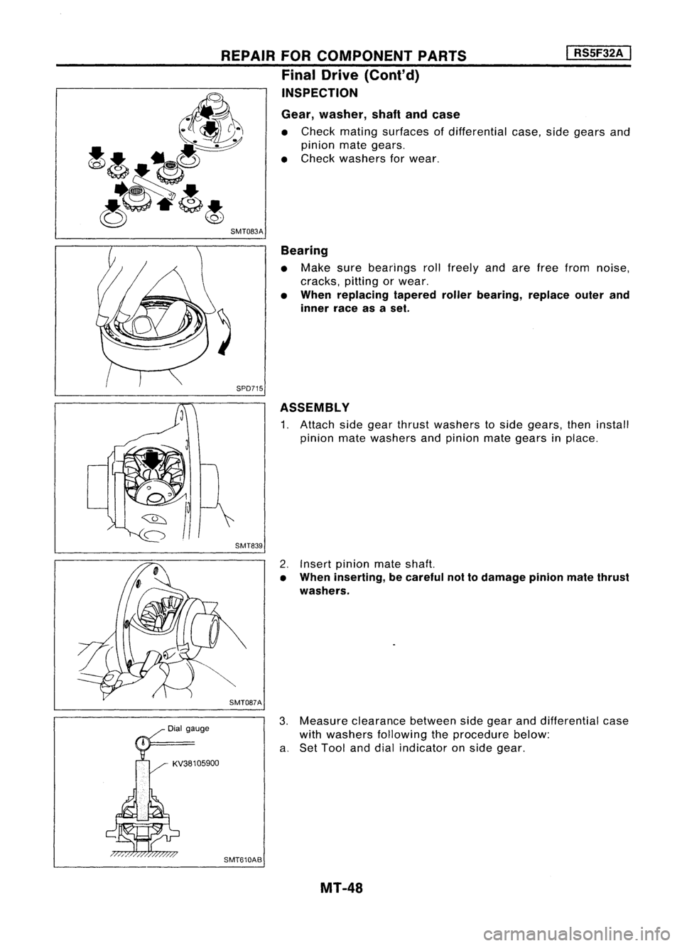
1. Attach sidegear thrust washers toside gears, theninstall
pinion matewashers andpinion mategears inplace.
I
RS5F32A
I
Gear, washer, shaftandcase
• Check mating surfaces ofdifferential case,sidegears and
pinion mategears.
• Check washers forwear.
Bearing
• Make surebearings rollfreely andarefree from noise,
cracks, pittingorwear.
• When replacing taperedrollerbearing, replaceouterand
inner raceasaset.
REPAIR
FORCOMPONENT PARTS
Final Drive (Cont'd)
INSPECTION
SMT839
KV381 05900
2.
Insert pinion mateshaft.
• When inserting, becareful nottodamage pinionmatethrust
washers.
3. Measure clearance betweensidegear anddifferential case
with washers following theprocedure below:
a. Set Tool anddial indicator onside gear.
SMT610AB MT-48