1995 NISSAN ALMERA N15 RS SRS
[x] Cancel search: RS SRSPage 1638 of 1701
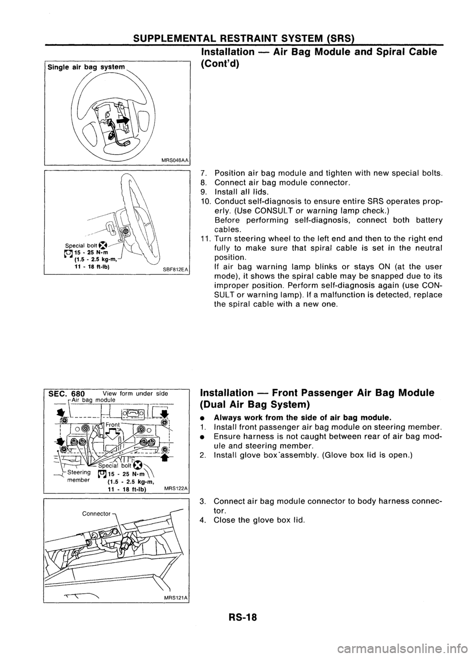
7.Position airbag module andtighten withnewspecial bolts.
8. Connect airbag module connector.
9. Install alllids.
10. Conduct self-diagnosis toensure entireSRSoperates prop-
erly. (Use CONSULT orwarning lampcheck.)
Before performing self-diagnosis, connectbothbattery
cables.
11. Turn steering wheeltothe leftend andthen tothe right end
fully tomake surethatspiral cableisset inthe neutral
position.
If air bag warning lampblinks orstays ON(atthe user
mode), itshows thespiral cablemaybesnapped duetoits
improper position.Performself-diagnosis again(useCON-
SUL Tor warning lamp).Ifa malfunction isdetected, replace
the spiral cablewithanew one.
SBF812EA
MRS046AA
SUPPLEMENTAL
RESTRAINTSYSTEM(SRS)
Installation -Air Bag Module andSpiral Cable
(Cont'd)
G\\
--------~
~\)
..~l~~
\\\?\\
Special bolt~~ "'(\\
cc:J
15-25 N.m ~
(1.5 -2.5 kg-m,
11 -18 ft-Ibl
Installation-Front Passenger AirBag Module
(Dual AirBag System)
• Always workfromtheside ofair bag module.
1. Install frontpassenger airbag module onsteering member.
• Ensure harness isnot caught between rearofair bag mod-
ule and steering member.
2. Install glovebox'assembly. (Gloveboxlidisopen.)
3. Connect airbag module connector tobody harness connec-
tor.
4. Close theglove boxlid.
RS-18
Page 1639 of 1701
SUPPLEMENTALRESTRAINTSYSTEM(SRS)
Disposal ofAir Bag Module andSeat Belt
Pre-tensioner
• Before disposing ofair bag module andseat beltpre-tensioner, orvehicles equipped withsuch
systems, deploythesystems. Ifsuch systems havealready beendeployed duetoan accident, dis-
pose ofas indicated in"DISPOSING OFAIR BAG MODULE ANDSEAT BELTPRE-TENSIONER" (RS-
24).
• When deploying theairbag module, alwaysusetheSpecial Service Tool;Deployment tool
KV99106400.
• When deploying theairbag module andseat beltpre-tensioner, standatleast 5m (16 ft)away from
the deployment component.
• Due toheat, leave airbag module unattended formore than30minutes afterdeployment. Alsoleave
seat beltpre-tensioner unattendedformore than10minutes afterdeployment.
• Besure towear gloves whenhandling adeployed airbag module andseat beltpre-tensioner.
• Never applywater toadeployed airbag module.
• Wash yourhands cleanafterfinishing- work.
• Donot dispose ofthe airbag module andseat beltpre-tensioner un-deployed.
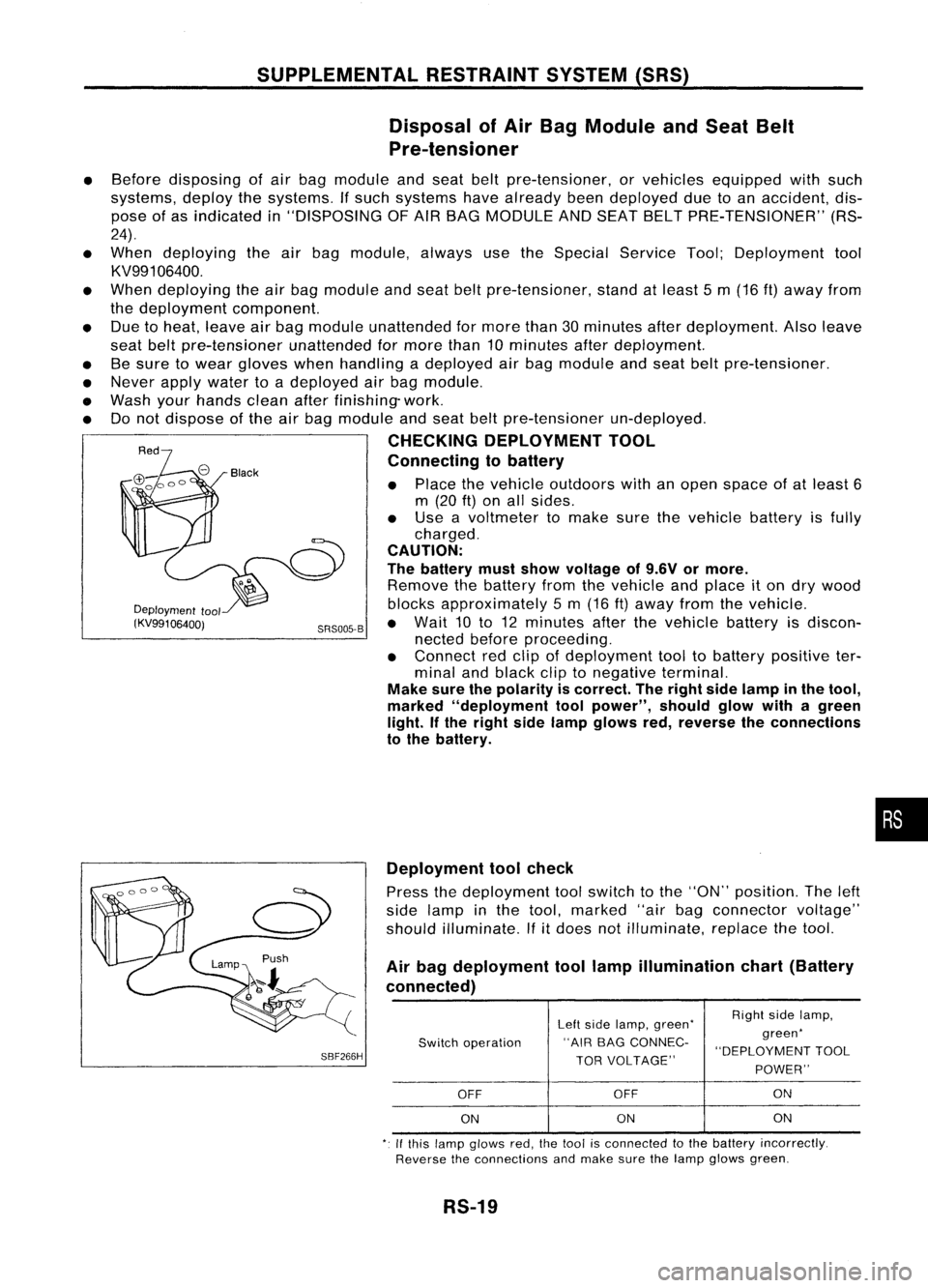
CHECKING DEPLOYMENT TOOL
Connecting tobattery
• Place thevehicle outdoors withanopen space ofat least 6
m (20
ft)
on allsides.
• Use avoltmeter tomake surethevehicle batteryisfully
charged.
CAUTION:
The battery mustshow voltage of9.6V ormore.
Remove thebattery fromthevehicle andplace iton dry wood
Deployment
tool blocksapproximately 5m (16 ft)away fromthevehicle.
(KV99106400j SRS005-B•
Wait 10to12 minutes afterthevehicle batteryisdiscon-
nected beforeproceeding.
• Connect redclip ofdeployment tooltobattery positive ter-
minal andblack cliptonegative terminal.
Make surethepolarity iscorrect. Theright sidelamp inthe tool,
marked "deployment toolpower", shouldglowwithagreen
light. Ifthe right sidelamp glows red,reverse theconnections
to the battery.
•
SBF266H Deployment
toolcheck
Press thedeployment toolswitch tothe "ON" position. Theleft
side lamp inthe tool, marked "airbagconnector voltage"
should illuminate.
If
it
does notilluminate, replacethetool.
Air bag deployment toollamp illumination chart(Battery
connected)
Leftside lamp, green' RighI
sidelamp,
Switch operation "AIR
BAGCONNEC- green'
"DEPLOYMENT TOOL
TOR VOLTAGE"
POWER"
OFF OFF ON
ON ON
ON
,. Ifthis lamp glows red,the1001 isconnecled tothe battery incorrectly.
Reverse theconnections andmake surethelamp glows green.
RS-19
Page 1640 of 1701
"'-Passenger airbag bracket
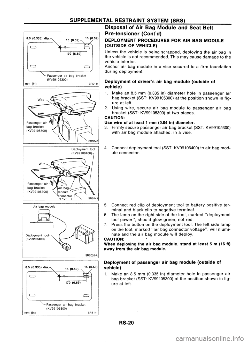
(KV99105300) Deploymentofdriver's airbag module (outside of
vehicle)
1. Make an8.5 mm (0.335 in)diameter holeinpassenger air
bag bracket (SST:KV99105300) atthe position showninfig-
ure atleft.
2. Using wire,secure airbag module topassenger airbag
bracket (SST:KV99105300) attwo places.
CAUTION:
Use wire ofal least 1mm (0.04 in)diameter.
3. Firmly secure passenger airbag bracket (SST:KV99105300)
with airbag module attached, inavise.
4. Connect deployment tool(SST: KV99106400) toair bag mod-
ule connector.
5. Connect redclip ofdeployment tooltobattery positive ter-
minal andblack cliptonegative terminal.
6. The lamp onthe right sideofthe tool, marked "deployment
tool power", shouldglowgreen, notred.
7. Press thebutton onthe deployment tool.Theleftside lamp
on the tool, marked "airbagconnector voltage",willillumi-
nate andtheairbag module willdeploy.
CAUTION:
When deploying theairbag module, standatleast 5m (16
ft)
away fromtheairbag module.
SRS141
SUPPLEMENTAL
RESTRAINTSYSTEM(SRS)
Disposal ofAir Bag Module andSeat Belt
Pre-tensioner (Cont'd)
DEPLOYMENT PROCEDURES FORAIRBAG MODULE
(OUTSIDE OFVEHICLE)
Unless thevehicle isbeing scrapped, deployingtheairbag in
the vehicle isnot recommended. Thismaycause damage tothe
vehicle interior.
Anchor airbag module inavise secured toafirm foundation
during deployment.
15
(0.59) 15(0.59)
°170
('.89~
Air bag module
Passenger
air
bag bracket
(KV99105300)
Passenger
air
bag bracket
(KV991 05300)
•.
5~335) dl"~
Deployment tool
(KV99106400)
mm
(in)
SRS020-A
15 (0.59) 15(0.59)
°'70 (.... ~
Deployment
ofpassenger airbag module (outside of
vehicle)
1. Make an8.5 mm (0.335 in)diameter holeinpassenger air
bag bracket (SST:KV99105300) atthe position showninfig-
ure atleft.
Passenger airbag bracket
(KV99105300)
mm (in)
SRS141
RS-20
Page 1641 of 1701
Airbag module
Deployment tool
(KV991 06400) SUPPLEMENTAL
RESTRAINTSYSTEM(SRS)
Disposal ofAir Bag Module andSeat Belt
Pre-tensioner (Cont'd)
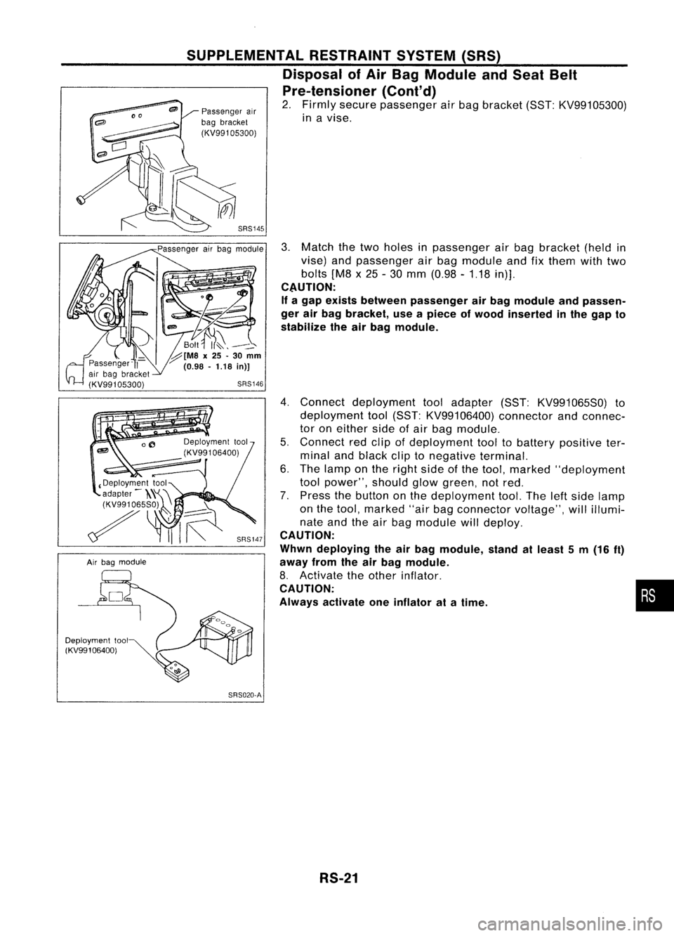
2. Firmly secure passenger airbag bracket (SST:KV99105300)
in avise.
SRS145
3.Match thetwo holes inpassenger airbag bracket (heldin
vise) andpassenger airbag module andfixthem withtwo
bolts [M8x25 -30 mm (0.98 -1.18 in)].
CAUTION:
If a gap exists between passenger airbag module andpassen-
ger airbag bracket, useapiece ofwood inserted inthe gap to
stabilize theairbag module.
4. Connect deployment tooladapter (SST:KV991065S0) to
deployment tool(SST: KV99106400) connectorandconnec-
tor oneither sideofair bag module.
5. Connect redclip ofdeployment tooltobattery positive ter-
minal andblack cliptonegative terminal.
6. The lamp onthe right sideofthe tool, marked "deployment
tool power", shouldglowgreen, notred.
7. Press thebutton onthe deployment tool.Theleftside lamp
on the tool, marked "airbagconnector voltage",willillumi-
nate andtheairbag module willdeploy.
CAUTION:
Whwn deploying theairbag module, standatleast 5m (16
ft)
away fromtheairbag module.
8. Activate theother inflator.
CAUTION:
Always activate oneinflator atatime.
SRS020-A!
RS-21
•
Page 1642 of 1701
SBF240F
SRS006-B
SUPPLEMENTAL
RESTRAINTSYSTEM(SRS)
Disposal ofAir Bag Module andSeat Belt
Pre-tensioner (Cont'd)
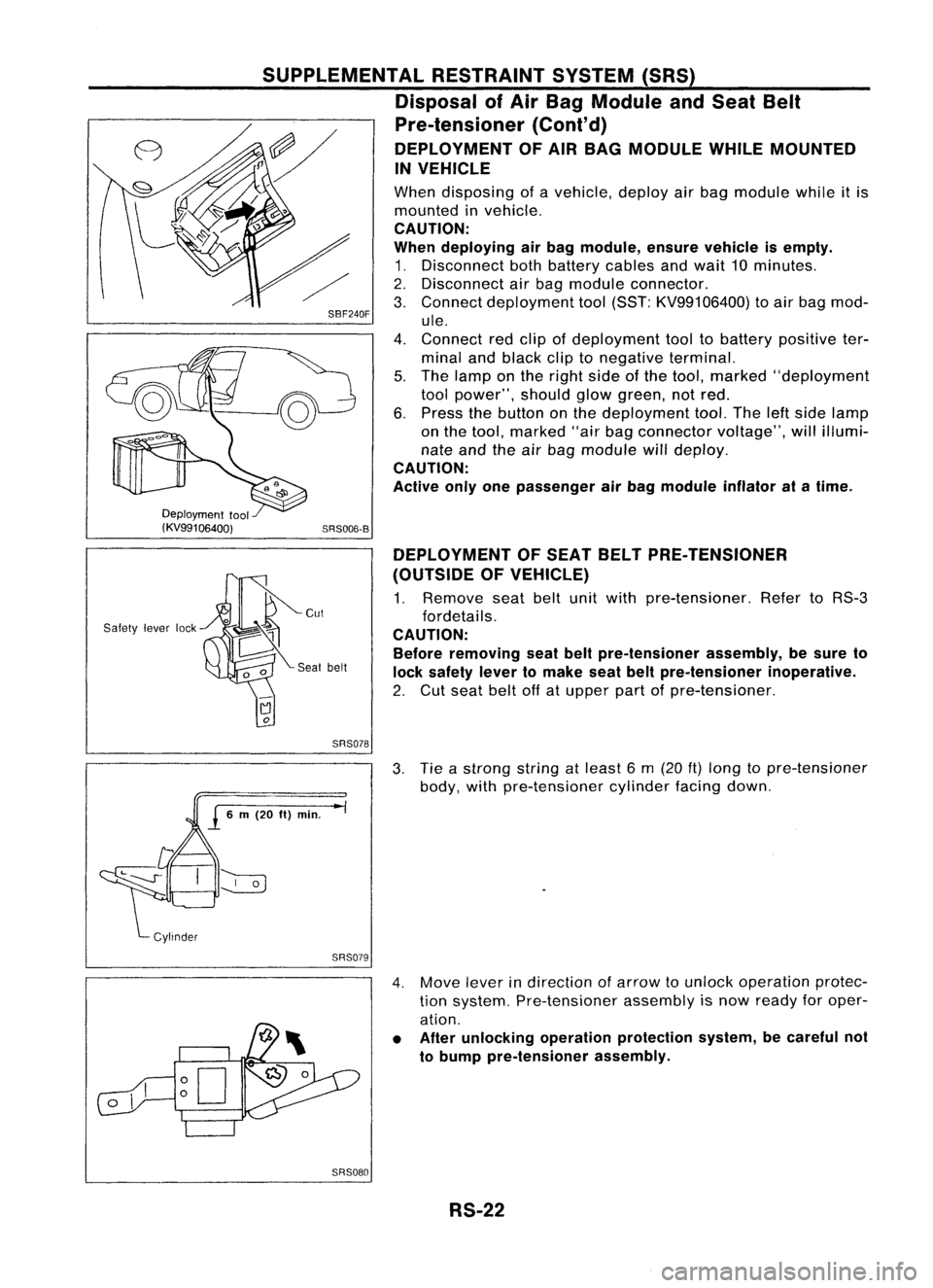
DEPLOYMENT OFAIR BAG MODULE WHILEMOUNTED
IN VEHICLE
When disposing ofavehicle, deployairbag module whileitis
mounted invehicle.
CAUTION:
When deploying airbag module, ensurevehicle isempty.
1. Disconnect bothbattery cablesandwait 10minutes.
2. Disconnect airbag module connector.
3. Connect deployment tool(SST: KV99106400) toair bag mod-
ule.
4. Connect redclip ofdeployment tooltobattery positive ter-
minal andblack cliptonegative terminal.
5. The lamp onthe right sideofthe tool, marked "deployment
tool power", shouldglowgreen, notred.
6. Press thebutton onthe deployment tool.Theleftside lamp
on the tool, marked "airbagconnector voltage",willillumi-
nate andtheairbag module willdeploy.
CAUTION:
Active onlyonepassenger airbag module inflatoratatime.
Deployment tool
(KV99106400)
Safety leverlock DEPLOYMENT
OFSEAT BELTPRE-TENSIONER
(OUTSIDE OFVEHICLE)
1. Remove seatbeltunitwith pre-tensioner. RefertoRS-3
fordetails.
CAUTION: Before removing seatbeltpre-tensioner assembly,besure to
lock safety levertomake seatbeltpre-tensioner inoperative.
2. Cut seat beltoffatupper partofpre-tensioner.
SRS078
3.Tie astrong stringatleast 6m (20
ft)
long topre-tensioner
body, withpre-tensioner cylinderfacingdown.
SRS079
4.Move leverindirection ofarrow tounlock operation protec-
tion system. Pre-tensioner assemblyisnow ready foroper-
ation.
• After unlocking operationprotection system,becareful not
to bump pre-tensioner assembly.
SRS080 RS-22
Page 1643 of 1701
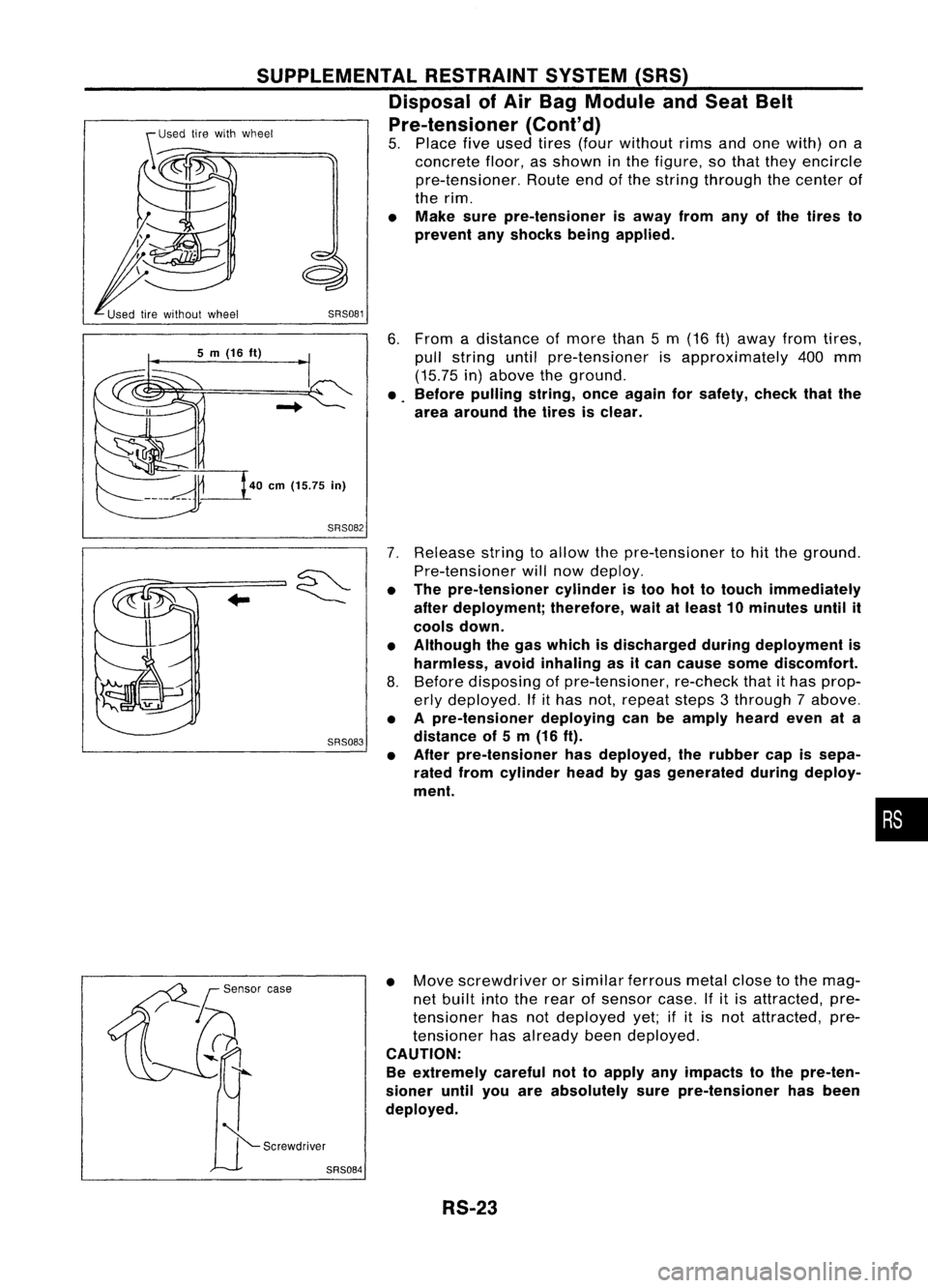
6.From adistance ofmore than5m (16
ft)
away fromtires,
pull string untilpre-tensioner isapproximately 400mm
(15.75 in)above theground.
• Before pulling string,onceagain forsafety, checkthatthe
area around thetires isclear.
SRS081
SUPPLEMENTAL
RESTRAINTSYSTEM(SRS)
Disposal ofAir Bag Module andSeat Belt
Pre-tensioner (Cont'd)
5. Place fiveused tires(four without rimsandonewith) ona
concrete floor,asshown inthe figure, sothat they encircle
pre-tensioner. Routeendofthe string through thecenter of
the rim.
• Make surepre-tensioner isaway fromanyofthe tires to
prevent anyshocks beingapplied.
40
em
(15.75
in)
5
m
(16
ft)
SRS082
SRS083
7.
Release stringtoallow thepre-tensioner tohit the ground.
Pre-tensioner willnow deploy.
• The pre-tensioner cylinderistoo hottotouch immediately
after deployment; therefore,waitatleast 10minutes untilit
cools down.
• Although thegas which isdischarged duringdeployment is
harmless, avoidinhaling asitcan cause somediscomfort.
8. Before disposing ofpre-tensioner, re-checkthatithas prop-
erly deployed. Ifithas not,repeat steps3through 7above.
• Apre-tensioner deployingcanbeamply heardevenata
distance of5m (16 ft).
• After pre-tensioner hasdeployed, therubber capissepa-
rated fromcylinder headbygas generated duringdeploy-
ment.
•
• Move screwdriver orsimilar ferrous metalclosetothe mag-
net built intotherear ofsensor case.Ifitis attracted, pre-
tensioner hasnotdeployed yet;ifit is not attracted, pre-
tensioner hasalready beendeployed.
CAUTION:
Be extremely carefulnottoapply anyimpacts tothe pre-ten-
sioner untilyouareabsolutely surepre-tensioner hasbeen
deployed.
RS-23
Page 1644 of 1701
SBF276H
SUPPLEMENTAL
RESTRAINTSYSTEM(SRS)
Disposal ofAir Bag Module andSeat Belt
Pre-tensioner (Cont'd)
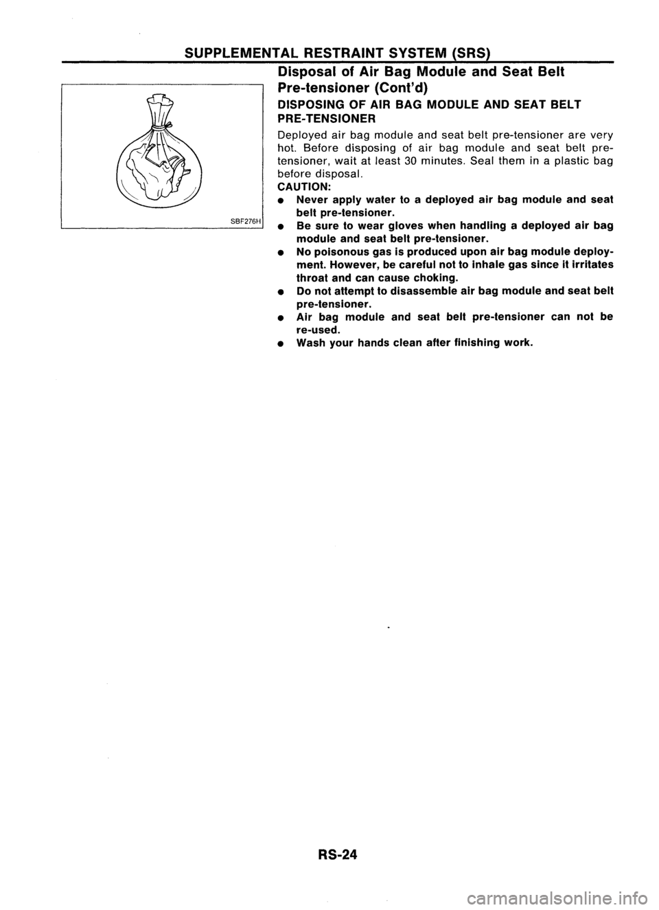
DISPOSING OFAIR BAG MODULE ANDSEAT BELT
PRE- TENSIONER
Deployed airbag module andseat beltpre-tensioner arevery
hot. Before disposing ofair bag module andseat beltpre-
tensioner, waitatleast 30minutes. Sealthem inaplastic bag
before disposal.
CAUTION:
• Never applywater toadeployed airbag module andseat
belt pre-tensioner.
• Besure towear gloves whenhandling adeployed airbag
module andseat beltpre-tensioner.
• Nopoisonous gasisproduced uponairbag module deploy-
ment. However, becareful nottoinhale gassince itirritates
throat andcancause choking.
• Donot attempt todisassemble airbag module andseat belt
pre-tensioner.
• Air bag module andseat beltpre-tensioner cannotbe
re-used.
• Wash yourhands cleanafterfinishing work.
RS-24
Page 1645 of 1701
TROUBLEDIAGNOSES -Supplemental RestraintSystem(SRS)
How toPerform TroubleDiagnoses forQuick
and Accurate Repair
A good understanding ofthe malfunction conditionscanmake troubleshooting fasterandmore accurate.
In general, eachcustomer feelsdifferently aboutaproblem. Itis important tofully understand the
symptoms orconditions foracustomer complaint.
INFORMATION FROMCUSTOMER
WHAT Vehiclemodel
WHEN Date,Frequencies
WHERE Roadconditions
HOW Operatingconditions, Symptoms
PRELIMINARY CHECK
Check thatthefollowing partsareingood" order.
• Battery [RefertoMA section ("GENERAL MAINTENANCE").]
• Fuse [Refer toEL section ("Fuse", "POWER SUPPLYROUTING").]
• System component-to-harness connections
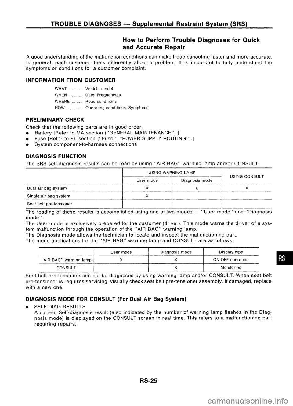
DIAGNOSIS FUNCTION
The SRS self-diagnosis resultscanberead byusing "AIRBAG" warning lampand/or CONSULT.
USING WARNING LAMP
USINGCONSULT
User mode Diagnosismode
Dual airbag system
X
X X
Single airbag system
X
Seat beltpre-tensioner
The reading ofthese results isaccomplished usingoneoftwo modes -"User mode" and"Diagnosis
mode".
The User mode isexclusively preparedforthe customer (driver).Thismode warns thedriver ofasys-
tem malfunction throughtheoperation ofthe "AIR BAG" warning lamp.
The Diagnosis modeallows thetechnician tolocate andinspect themalfunctioning part.
The mode applications forthe "AIR BAG" warning lampandCONSULT areasfollows:
User mode Diagnosis
mode Displaytype
"AIR BAG" warning lamp
X
X
ON-OFF
operation
CONSULT
X
Monitoring
Seat beltpre-tensioner cannotbediagnosed byusing warning lampand/or CONSULT. Whenseatbelt
pre-tensioner isrequires servicing, visuallycheckseatbeltpre-tensioner assembly.Ifdamaged, replace
with anew one.
DIAGNOSIS MODEFORCONSULT (ForDual AirBag System)
• SELF-DIAG RESULTS
A current Self-diagnosis result(alsoindicated bythe number ofwarning lampflashes inthe Diag-
nosis mode) isdisplayed onthe CONSULT screeninreal time. Thisrefers toamalfunctioning part
requiring repairs.
RS-25
•