Page 1630 of 1701
SUPPLEMENTALRESTRAINTSYSTEM(SRS)
SRS Component PartsLocation
Dual airbag system andseat beltpre-tensioner
SEC. 251-253-484-680-868 Spiralcable Airbag module
Diagnosis sensorunit
Single airbag system andseat beltpre-tensioner
SEC. 253-484-868 Airbag module
Diagnosis sensorunit
RS-10 MRS114A
Page 1631 of 1701
SUPPLEMENTALRESTRAINTSYSTEM(SRS)
Visually checkSRScomponents
Diagnosis sensorunit
Check diagnosis sensorunitand bracket fordents, cracks
or deformities.
Check connectors fordamage, andterminals fordeformi-
ties.
Air bag module andsteering wheel
Remove airbag module fromsteering wheelorinstrument
panel. Check harness coverandconnectors fordamage,
terminals fordeformities, andharness forbinding.
Install driversideairbag module tosteering wheeltocheck
fit or alignment withthewheel.
Check steering wheelforexcessive freeplay.
For dual airbag system, installpassenger sideairbag
module toinstrument paneltocheck fitor alignment withthe
instrument panel.
Maintenance
Items
1. Check "AIRBAG" warning lampoperation
After turning ignition keyto"ON" position, "AIRBAG"
warning lampilluminates. The"AIR BAG" warning lamp
will turn offafter about 7seconds ifno malfunction is
detected. If any ofthe following airbag warning lampconditions
occur, immediately checktheairbag system. RefertoRS-32
and 43for details.
The warning lampdoesnotilluminate whentheignition
switch isturned "ON".
The warning lampdoesnotturn offabout 7seconds after
the ignition switchisturned "ON".
The warning lampturns offabout 7seconds aftertheigni-
tion switch isturned "ON",butitturns onorflashes again.
•
MRS115A
•
•
2. (1)
•
•
(2)
•
•
•
•
(3) Spiral cable
• Check spiralcablefordents, cracks, ordeformities.
• Check connectors andprotective tapefordamage.
• Check steering wheelfornoise, binding orheavy operation. •
(4) Main harness andairbag harness (Fordual airbag system
only)
• Check connectors forpoor connections, damage,andtermi-
nals fordeformities.
• Check harnesses forbinding, chafingorcut.
CAUTION: Replace previously usedscrews withnewones.
RS-11
Page 1632 of 1701
SUPPLEMENTALRESTRAINTSYSTEM(SRS)
Removal andInstallation -Diagnosis Sensor
Unit
CAUTION:
• Before servicing SRS,turntheignition switchoff,disconnect bothbattery cablesandwait foratleast
10 minutes.
• The special boltsarecoated withbonding agentwhiletheother boltisfor ground. Donot use old
bolts afterremoval; replacewithnewones.
• For single airbag system, donot separate diagnosis sensorunitfrom steering wheel.
• For dual airbag system, checkdiagnosis sensorunitforproper installation.
• Check diagnosis sensorunittoensure theyarefree ofdeformities, dents,cracks orrust. Ifthey show
any visible signsofdamage, replacethemwithnewones.
• Check diagnosis sensorunitbrackets toensure theyarefree ofdeformities orrust.
• Always workfromtheside ofair bag module.
• Replace diagnosis sensorunitifithas been dropped orsustained animpact.
SEC. 253~
IT
r
Grou~? bolt~
G ~~ ~
Forward mark
Fr?nt
_--I
d--!
Dia~no:iS senSlrunit
!
Special bOIt~ -
t"'J
15-25 N.m
(1.5 •2.5 kg-m,
11-
18 ft-Ib)
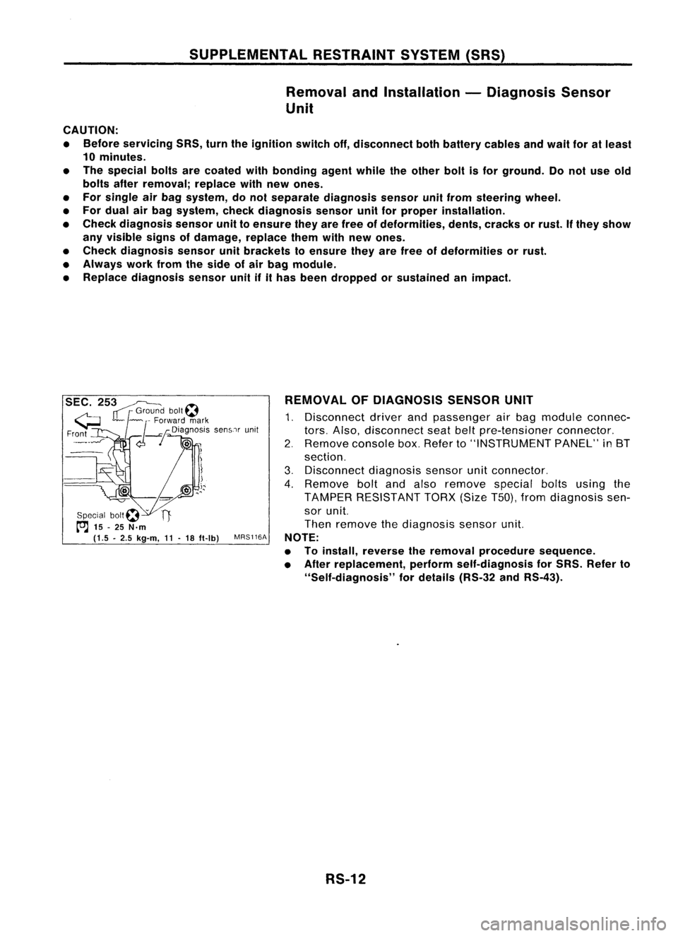
MRS116A REMOVAL
OFDIAGNOSIS SENSORUNIT
1. Disconnect driverandpassenger airbag module connec-
tors. Also, disconnect seatbeltpre-tensioner connector.
2. Remove consolebox.Refer to"INSTRUMENT PANEL"in8T
section.
3. Disconnect diagnosissensorunitconnector.
4. Remove boltandalso remove specialboltsusing the
TAMPER RESISTANT TORX(SizeT50),fromdiagnosis sen-
sor unit.
Then remove thediagnosis sensorunit.
NOTE:
• Toinstall, reverse theremoval procedure sequence.
• After replacement, performself-diagnosis forSRS. Refer to
"Self-diagnosis" fordetails (RS-32andRS-43).
RS-12
Page 1633 of 1701
SUPPLEMENTALRESTRAINTSYSTEM(SRS)
Removal andInstallation -Seat Belt
Pre-tensioner (MechanicalType)
CAUTION:
• Donot attempt todisassemble seatbeltpre-tensioner assembly.
• Donot drop orimpact seatbeltpre-tensioner assembly.Thismay cause seatbeltpre-tensioner to
deploy.
• Check seatbeltpre-tensioner assemblyfordamage ordeformities.
• Replace seatbeltpre-tensioner assemblythatshows anyvisible signofdamage.
• Donot expose seatbeltpre.tensioner totemperatures exceeding80°C(176°F).
Seat beltpre-tensioner retracter
SEC. 868
(4.4-5.6 kg-m,
32 -41 fl-Ib) For
removal ofseat beltpre-tensioner, referto"Front Seat
Belt" fordetails (RS-3).
CAUTION:
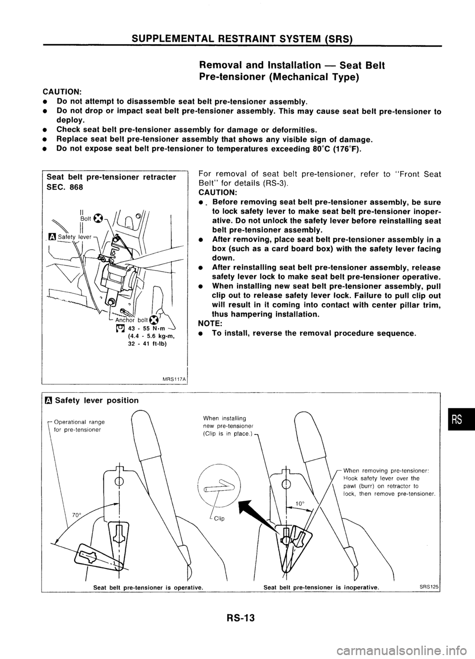
• Before removing seatbeltpre-tensioner assembly,besure
to lock safety levertomake seatbeltpre-tensioner inoper-
ative. Donot unlock thesafety leverbefore reinstalling seat
belt pre-tensioner assembly.
• After removing, placeseatbeltpre-tensioner assemblyina
box (such asacard board box)withthesafety leverfacing
down.
• After reinstalling seatbeltpre-tensioner assembly,release
safety leverlocktomake seatbeltpre-tensioner operative.
• When installing newseat beltpre-tensioner assembly,pull
clip outtorelease safetyleverlock.Failure topull clipout
will result initcoming intocontact withcenter pillartrim,
thus hampering installation.
NOTE:
• Toinstall, reverse theremoval procedure sequence.
MRS117AI
[i]
Safety leverposition
Operational range
for pre-tensioner When
installing
new pre-tensioner
(Clip isinplace.)
When
removing
pre-tensioner:
Hook safety
leverover
the
pawl (burr) onretractor to
lock, then
remove
pre-tensioner.
•
Seat beltpre-tensioner isoperative.
RS-13
Seat
beltpre-tensioner isinoperative.
SRS125
Page 1634 of 1701
SUPPLEMENTALRESTRAINTSYSTEM(SRS)
Removal andInstallation -Air Bag Module and
Spiral Cable(DualAirBag System)
SEC. 253-484
Horn relayswitch connector
Special bolt~
to:J
15-25 (1.5 -2.5,
11-
18)
to:J :
N.m (kg-m. ft-Ib) Special
bolt~
to:J
15.25 (1.5•2.5,
11•
18)
Side lidRH
Air bag module
to:J
29-39 (3.0 -4.0, 22-29)
Lower lid
MRS118A
Removal andInstallation -Air Bag Module and
Spiral Cable(Single AirBag System)
SEC. 253-484
Airbag module connector
Spiral cable
A'
Special bolt~ ~
t"J
15•25 (1.5 •2.5, 11•18)- ~
Side lidLH/
"-J
to:J :
N. m (kg-m. ft-Ib) ~DiagnOSiS
sensorunit
(Do notseparate thediagnosis
sensor unitfrom steering wheel.)
Special boll~
to:J
15-25 (1.5 -2.5,
11-
18)
~~ r
S;d, lidRH
~ (]A;,b'9
mod",
MRS119A
RS-14
Page 1635 of 1701
SUPPLEMENTALRESTRAINTSYSTEM(SRS)
Removal -Air Bag Module andSpiral Cable
CAUTION:
• Before servicing SRS,turntheignition switchoff,discon-
nect both battery cablesandwait foratleast 10minutes.
• Always workfromtheside ofair bag module.
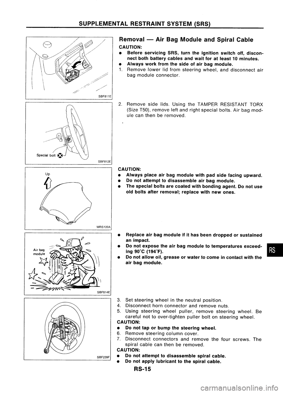
1. Remove lowerlidfrom steering wheel,anddisconnect air
bag module connector.
SBF811E
2.Remove sidelids.Using theTAMPER RESISTANT TORX
(Size T50), remove leftand right special bolts.Airbag mod-
ule can then beremoved.
SBF812E CAUTION:
• Always placeairbag module withpadside facing upward.
• Donot attempt todisassemble airbag module.
• The special boltsarecoated withbonding agent.Donot use
old bolts afterremoval; replacewithnew ones.
MRS120A
Air bag
module
SBF814E•
•
• Replace
airbag module ifithas been dropped orsustained
an impact.
Do not expose theairbag module totemperatures exceed-•
•
ing 90°C (194°F).
Do not allow oil,grease orwater tocome incontact withthe
air bag module.
SBF239F
3.
Set steering wheelinthe neutral position.
4. Disconnect hornconnector andremove nuts.
5. Using steering wheelpuller, remove steering wheel.Be
careful nottoover-tighten pullerboltonsteering wheel.
CAUTION:
• Donot tap orbump thesteering wheel.
6. Remove steering columncover.
7. Disconnect connectorsandremove thefour screws. The
spiral cablecanthen beremoved.
CAUTION:
• Donot attempt todisassemble spiralcable.
• Donot apply lubricant tothe spiral cable.
RS-15
Page 1636 of 1701
SUPPLEMENTALRESTRAINTSYSTEM(SRS)
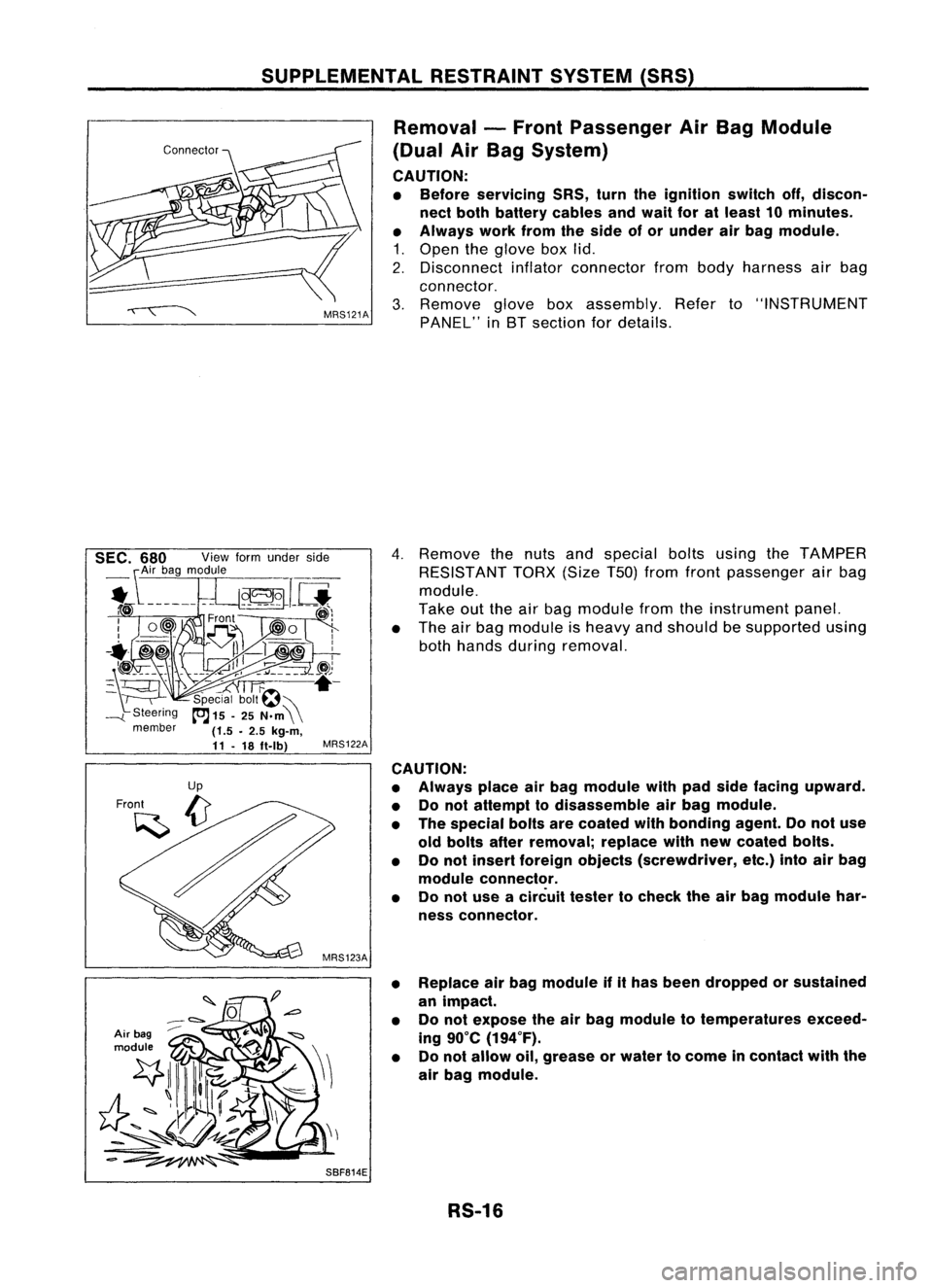
Removal -Front Passenger AirBag Module
(Dual AirBag System)
CAUTION:
• Before servicing SRS,turntheignition switchoff,discon-
nect both battery cablesandwait foratleast 10minutes.
• Always workfromtheside ofor under airbag module.
1. Open theglove boxlid.
2. Disconnect inflatorconnector frombody harness airbag
connector.
3. Remove gloveboxassembly. Referto"INSTRUMENT
PANEL" inBT section fordetails.
Air bag
module
4.
Remove thenuts andspecial boltsusing theTAMPER
RESISTANT TORX(SizeT50jfrom front passenger airbag
module.
Take outtheairbag module fromtheinstrument panel.
• The airbag module isheavy andshould besupported using
both hands during removal.
MRS122A
CAUTION:
• Always placeairbag module withpadside facing upward.
• Donot attempt todisassemble airbag module.
• The special boltsarecoated withbonding agent.Donot use
old bolts afterremoval; replacewithnewcoated bolts.
• Donot insert foreign objects (screwdriver, etc.)intoairbag
module connector.
• Donot use acircuit testertocheck theairbag module har-
ness connector.
• Replace airbag module ifithas been dropped orsustained
an impact.
• Donot expose theairbag module totemperatures exceed-
ing 90°C (194°F).
• Donot allow oil,grease orwater tocome incontact withthe
air bag module.
SBF814E RS-16
Page 1637 of 1701
SUPPLEMENTALRESTRAINTSYSTEM(SRS)
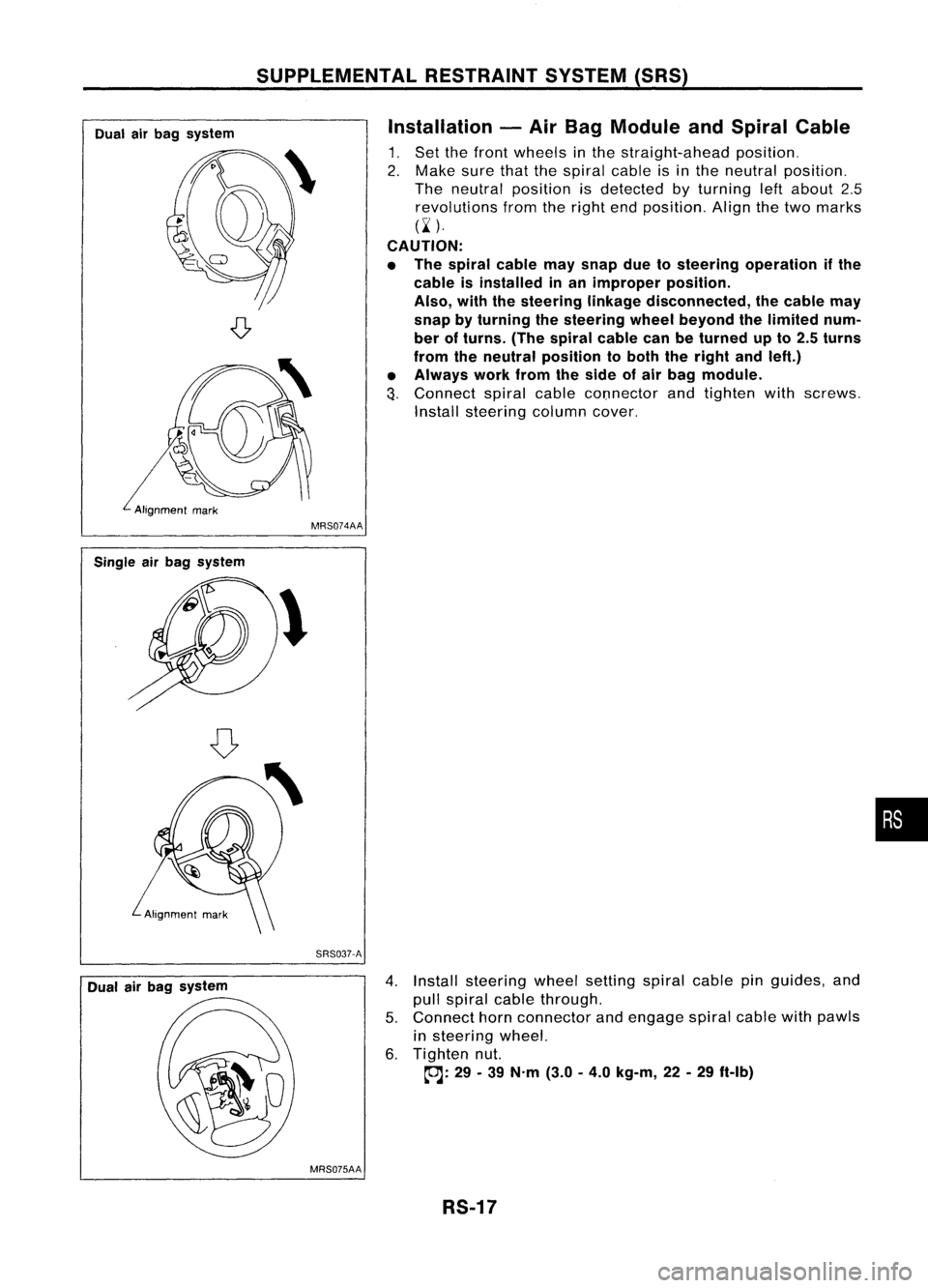
Dual airbag system Installation
-Air Bag Module andSpiral Cable
1. Set thefront wheels inthe straight-ahead position.
2. Make surethatthespiral cableisin the neutral position.
The neutral position isdetected byturning leftabout 2.5
revolutions fromtheright endposition. Alignthetwo marks
(~ ).
CAUTION:
• The spiral cablemaysnap duetosteering operation ifthe
cable isinstalled inan improper position.
Also, withthesteering linkagedisconnected, thecable may
snap byturning thesteering wheelbeyond thelimited num-
ber ofturns. (Thespiral cablecanbeturned upto2.5 turns
from theneutral position toboth theright andleft.)
• Always workfromtheside ofair bag module.
3.
Connect spiralcablecOnnector andtighten withscrews.
Install steering columncover.
Single airbag system
Dual airbag system MRS074AA
SRS037-A
4.Install steering wheelsetting spiralcablepinguides, and
pull spiral cablethrough.
5. Connect hornconnector andengage spiralcablewithpawls
in steering wheel.
6. Tighten nut.
~: 29-39 N'm (3.0-4.0 kg-m, 22-29 ft-Ib)
MRS075AA RS-17
•