Page 1646 of 1701
SRS102
TROUBLE
DIAGNOSES -Supplemental RestraintSystem(SRS)
How toPerform TroubleDiagnoses forQuick
and Accurate Repair(Cont'd)
• ECU DISCRIMINATED NO.
The diagnosis sensorunitforeach vehicle modelis
assigned withitsown, individual classification number.This
number willbedisplayed onthe CONSULT screen,as
shown atleft. When replacing thediagnosis sensorunit,
refer tothe part number forthe compatibility. After
installation, replacement withacorrect unitcan bechecked
by confirming thisclassification numberonthe CONSULT
screen.
For NISSAN modelN15,thediagnosis sensorunitclassifi-
cation number assigned is09.
•
ECU DISCRIMINATED No.•
ECU No.
09
RS-26
Page 1647 of 1701

TROUBLEDIAGNOSES -Supplemental RestraintSystem(SRS)
How toPerform TroubleDiagnoses forQuick
and Accurate Repair(Cont'd)
CAUTION:
• Donot use acircuit testertocheck SRSharness connectors unlessinstructed tointhis Service
Manual. Fordual airbag system, SRSwiring harnesses arecovered withyellow insulation either
just before theharness connectors orfor complete harness,foreasy identification.
• Donot attempt torepair, spliceormodify theSRS wiring harness. Ifthe harness isdamaged, replace
it with anew one.
• Keep ground portionclean.
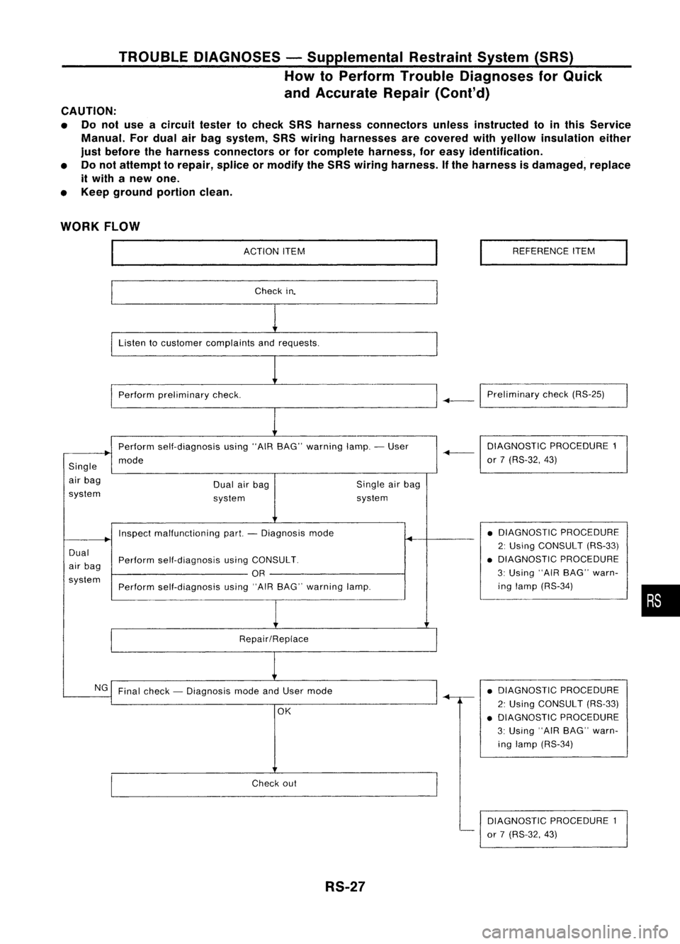
WORK FLOW
ACTIONITEM
Check in.
Listen tocustomer complaints andrequests.
Perform preliminary check. REFERENCE
ITEM
-+-1
Preliminary check(RS-25)
Perform self-diagnosis using"AIRBAG" warning lamp.-User
mode
Single
air bag
system Dual
airbag
system Single
airbag
system DIAGNOSTIC
PROCEDURE1
-+-
or7(RS-32, 43)
Dual
air bag
system Inspect
malfunctioning part.-Diagnosis mode
Perform self-diagnosis usingCONSULT.
OR
Perform self-diagnosis using"AIRBAG" warning lamp.
Repair/Replace •
DIAGNOSTIC PROCEDURE
2: Using CONSULT (RS-33)
• DIAGNOSTIC PROCEDURE
3: Using "AIRBAG" warn-
ing lamp (RS-34)
•
NG Final check -Diagnosis modeandUser mode
OK
Check out
RS-27 •
DIAGNOSTIC PROCEDURE
2: Using CONSULT (RS-33)
• DIAGNOSTIC PROCEDURE
3: Using "AIRBAG" warn-
ing lamp (RS-34)
DIAGNOSTIC PROCEDURE1
or 7(RS-32, 43)
Page 1648 of 1701
TROUBLEDIAGNOSES -Supplemental RestraintSystem(SRS)-
Dual AirBag System
Schematic
FUSE
DUAL
AIRBAG SYSTEM
DATA LINK
CONNECTOR
FOR CONSULT
o
FUSE
COMBINAnON
METER
(AIR BAG
WARNING
LAMP)
19
3
2120
4
5
6
2
15
17
AIR
BAG
DIAGNOSIS
SENSOR UNIT
SPIRAL
CABLE
AIR BAG
MODULE
DRIVER'S
SQUIB SIDE AIR
BAG
MODULE
PASSENGER
SQUIB SIDE
RS-28
-
DOOR SWITCH
DRIVER'S SIDE
HRS002
Page 1649 of 1701
TROUBLEDIAGNOSES -Supplemental RestraintSystem(SRS)-
Dual AirBag System
Wiring Diagram -SRS -
DUAL AIRBAG SYSTEM
RS-SRS-02
IGNITION SWITCH
ON orSTART
::} ToAS-SAS-D.
•
Refer
toEL-POWER.
LHOmode Is
RHOmodels
@:
GAand SRengine
@:
CDengine
@:
Withtachometer
@:
Without tachometer
~f1 ...
@
30
@
40
,
*2
@
9
@
31
*3
@
16
'@
30
,
AIR
BAG
DIAGNOSIS
SENSOR
UNIT
ill)
FUSE
BLOCK
(JIB)
(M15)
10A
1221
IGN
GNO
~ B
~(ll)
C:J~
B
rn~
I
~g~~~CTOR-3
~:
JOINT
CONNECTOR-4
~~:
I
,..O~O-O-ID-
I
<:
R
:>
I~
B B B BB
1
L..t t.J
~ (M60)~
~
(ll)"
*~
BRIW ~ BRIW-.
COMBINATION BRIW
METER ~
(AIR BAG 111511
WARNING WIL
LAMP)
(M30)
~
10A
W
BIR
.....
~
11*.21
BIR
~----------------------------------~
Refertolast page
(Foldout page).
L ~
em
y
(IT)
y
~(M59):
~P
ITIII:illJIIIII
~:
~ BR
HRS004
RS-29
Page 1650 of 1701
TROUBLEDIAGNOSES -Supplemental RestraintSystem(SRS)-
Dual AirBag System
Wiring Diagram -SRS -
{Co nt'd)
RS-SRS-03
AIRBAG
DIAGNOSIS
SENSOR
UNIT
em
AIR BAG
MODULE
PASSENGER
SIDE (SQUIB)
t
SQ-
(PASS)
~
OR
SQ+
(PASS)
~
G
SPIRAL
CABLE
AIR BAG
MODULE
DRIVER'S
SIDE (SQUIB)
t
SQ-
(DR)
~
L
SQ+
(DR)
l!:jJJ
W
DOOR
SWITCH
DRIVER'S
SIDE
@)
OPEN
"=iJ
B
I
f.
B B
~ ~
(B11)
@
DOOR
SW
~
R
~@
ICiJI~
R
I
BOXNO.2
(..JOINT
R CONNECTORS)
I~I ~~: ; ~
R R
I"'m:\
~~
I~IC@
R
<;>
R
0
•
R
m
em
y
@
~cm
y ~ y
Refer
tolast page
(Foldout page).
~~@
5 6lil~1112 W
rfrnl(]ID
l]f
B
~
*6
A,.@
t!!Iy ~y
@
W
HRS005
RS-30
Page 1651 of 1701
TROUBLEDIAGNOSES -Supplemental RestraintSystem(SRS)-
Dual AirBag System
Wiring Diagram -SRS -(Cont'd)
RS-SRS-04
AIR BAG
OIAGNOSIS
SENSOR
UNIT
em
:
LHOmodels
: RHOmodels
@:
GAand SReng ine
@:
CDengine
*7 ...
10 6
,
*8 ...
9 3
,
G/B
~
GY/L
~
~
G/W
t
o
•
G/W
~
SSS
SSSSSS
ClK TXRX
~ ~11
2
.°1
G/W
@
GY
IL
G/B
IciJ~
1$~ -- -1$1
G/W
GY/L
G/B
i
II
G/W
GY/L
G/B
~ ~~JUNCTION BOXNO.2
II B.II 11*711 II*BII(JOINT CONNECTORS)
JOINT CONNECTOR-5
1*:1 II*.BI~:
GY/l
G/B
I I
FUSE
Referto
7 .5A BLOCK El-POWER.
rn
(JIB)
~
G
rtl
IGNITION
SWITCH
ON or START
4-J
B
I
To RS-SRS-02 {~B ~
i
<@-B~
•
em
Y
@
Y
Refer
tolast page
(Foldout page).
~Q@
~GY
~(M24):
~ OR
HRS006
RS-31
Page 1652 of 1701

TROUBLEDIAGNOSES -Supplemental RestraintSystem(SRS)-
Dual AirBag System
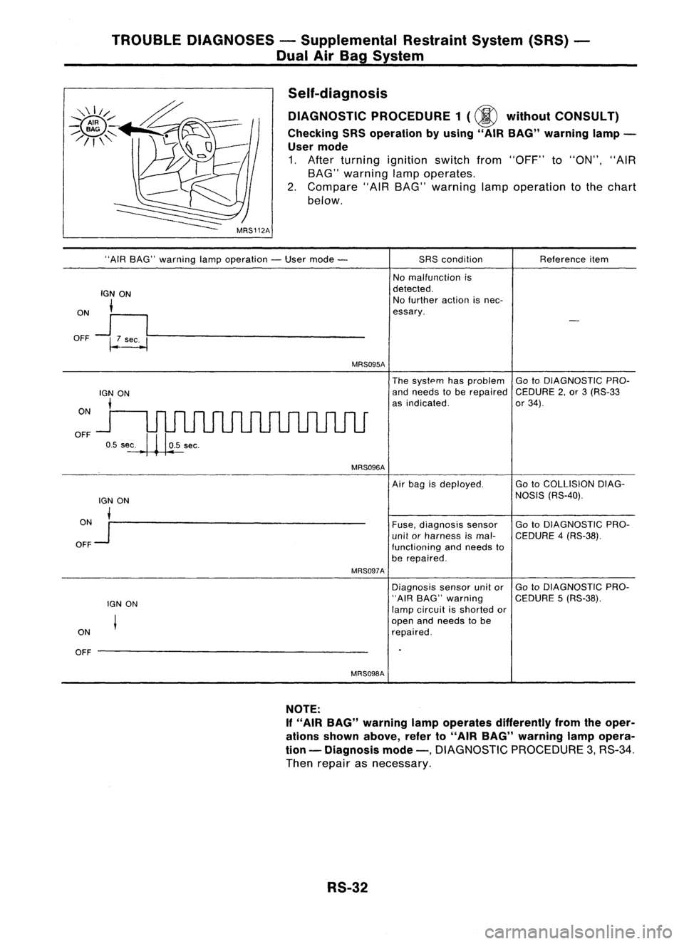
Self-diagnosis DIAGNOSTIC PROCEDURE 1(@ without CONSULT)
Checking SRSoperation byusing" AIRBAG" warning lamp-
User mode
1. After turning ignition switchfrom"OFF" to"ON", "AIR
BAG" warning lampoperates.
2. Compare "AIRBAG" warning lampoperation tothe chart
below.
"AIR BAG" warning lampoperation -User mode -
IGN ON
i
ON
J
I
OFF ~~----------------
MRS095A
SRS
condition
No malfunction is
detected. No further actionisnec-
essary. Reference
item
ON
OFF
The
system hasproblem GotoDIAGNOSTIC PRO-
and needs tobe repaired CEDURE2,or 3(RS-33
as indicated. or34).
MRS096A
lGN ON
ON •
OFF
Jr--------------------
MRS097A
IGN ON
ON
OFF --------------------
MRS098A
Air
bag isdeployed. GotoCOLLISION DIAG-
NOSIS (RS-40).
Fuse, diagnosis sensor GotoDIAGNOSTIC PRO-
unit orharness ismal- CEDURE 4(RS-38).
functioning andneeds to
be repaired.
Diagnosis sensorunitor GotoDIAGNOSTIC PRO-
"AIR BAG" warning CEDURE5(RS-38).
lamp circuit isshorted or
open andneeds tobe
repaired.
NOTE:
If "AIR BAG" warning lampoperates differently fromtheoper-
ations shown above, referto"AIR BAG" warning lampopera-
tion -Diagnosis mode-,
DIAGNOSTIC PROCEDURE3,RS-34.
Then repair asnecessary.
RS-32
Page 1653 of 1701
TROUBLEDIAGNOSES -Supplemental RestraintSystem(SRS)-
Dual AirBag System
Self-diagnosis (Cont'd)
DIAGNOSTIC PROCEDURE2
(00
withCONSULT)
Inspecting SRSmalfunctioning partsbyusing CONSULT -
Diagnosis mode
1. Turn ignition switch"OFF".
2. Connect "CONSULT" toData linkconnector.
MRS124A
AIRBAG SELF-DIAG RESULTS
NISSAN
CONSULT
START
SUB MODE
I
SRS046
I ~
SELECT SYSTEM
01
I
ENGINE
1
1 '
1-----1
I
I
I 1
MRS125A
I ~
SELECT DIAGMODE
01
I
ECUDISCRIMINATED NO.
I
'======
1 -
1 -
1========
SRS043
• SELF-DIAG RESULTS.
0
FAILURE DETECTED
CONTROL UNIT
I
ERASE
II
PRINT
I
SRS064
3.
Turn ignition switch"ON".
4. Touch "START".
5. Touch "AIRBAG".
6. Touch "SELF-DIAG RESULTS".
7. Diagnostic codesaredisplayed on"SELF-DIAG RESULTS".
RS-33
•