1995 NISSAN ALMERA N15 Idle speed control
[x] Cancel search: Idle speed controlPage 957 of 1701
EVAPORATIVEEMISSIONSYSTEM
Description
yAir.. Fuelvapor
EGR
valve
&
EVAP canister purgecontrol
solenoid valve
-
EVAP canister
Vapor
ventline
-
Fuel fillercap
with vacuum
relief valve
t
Fuel tank
MEF609DC
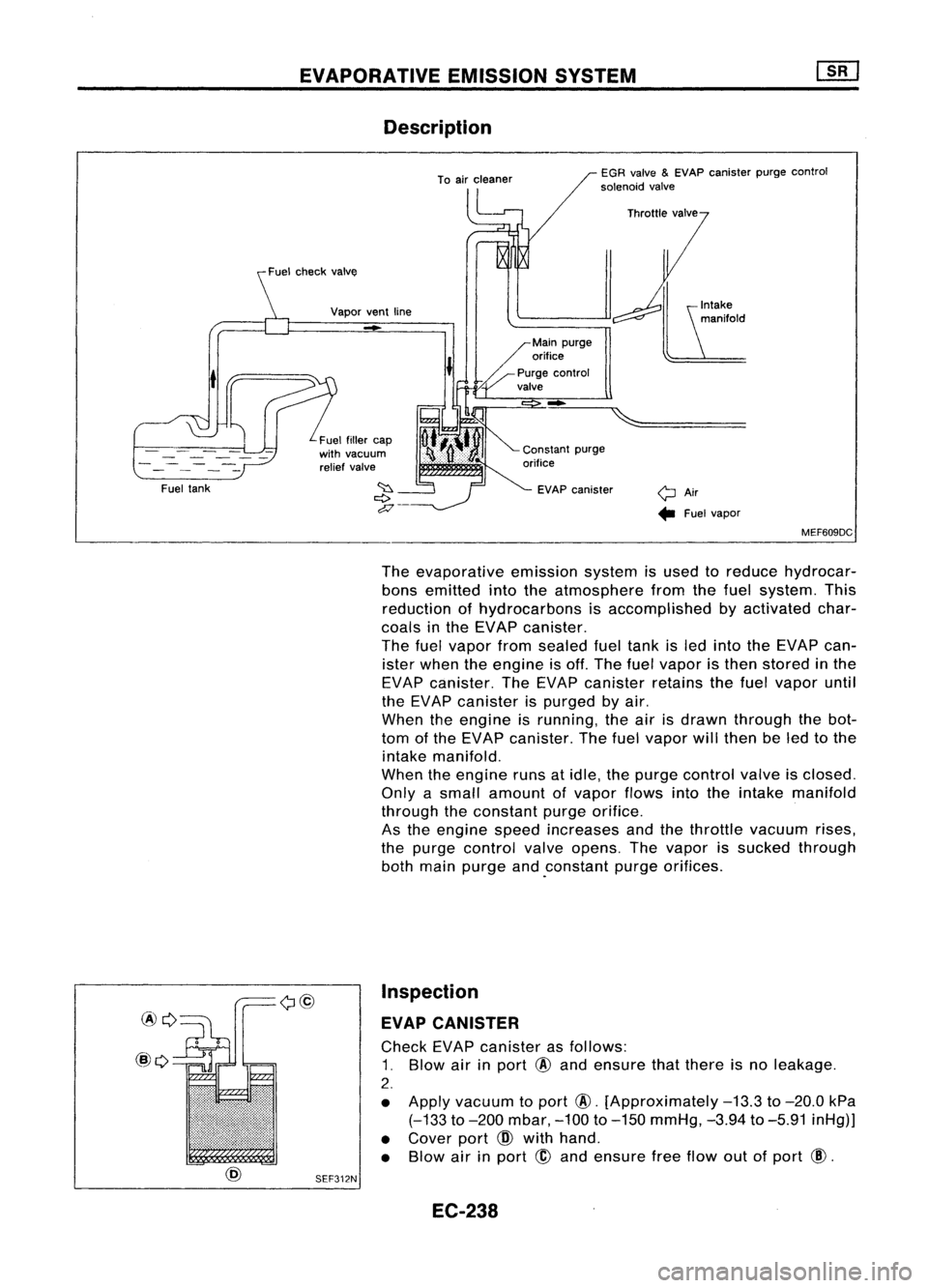
The evaporative emissionsystemisused toreduce hydrocar-
bons emitted intotheatmosphere fromthefuel system. This
reduction ofhydrocarbons isaccomplished byactivated char-
coals inthe EVAP canister.
The fuelvapor fromsealed fueltank isled into theEVAP can-
ister when theengine isoff. The fuelvapor isthen stored inthe
EVAP canister. TheEVAP canister retainsthefuel vapor until
the EVAP canister ispurged byair.
When theengine isrunning, theairisdrawn through thebot-
tom ofthe EVAP canister. Thefuelvapor willthen beled tothe
intake manifold.
When theengine runsatidle, thepurge control valveisclosed.
Only asmall amount ofvapor flowsintotheintake manifold
through theconstant purgeorifice.
As the engine speedincreases andthethrottle vacuum rises,
the purge control valveopens. Thevapor issucked through
both main purge and.constant purgeorifices.
Inspection
EVAP CANISTER
Check EVAPcanister asfollows:
1. Blow airinport
@
and ensure thatthere isno leakage.
2.
• Apply vacuum toport
@.
[Approximately
-13.3
to
-20.0
kPa
(-133
to
-200
mbar,
-100
to
-150
mmHg,
-3.94
to
-5.91
inHg)]
• Cover port
CID
with hand.
• Blow airinport
@
and ensure freeflow outofport
@.
SEF312N
EC-238
Page 962 of 1701

BASICSERVICE PROCEDURE
Idle Speedllgnition TiminglldleMixtureRatio
Adjustment
PREPARATION
• Make surethatthefollowing partsarein
good order.
(1) Battery
(2) Ignition system
(3) Engine oiland coolant levels
(4) Fuses
(5) ECM harness connector
(6) Vacuum hoses
(7) Airintake system
(Oil filler cap,oillevel gauge, etc.)
(8) Fuel pressure
(9) Engine compression
(10) Throttle valve
Overall inspection sequence
INSPECTION
•
•
•
•
•
•
On
models equipped withairconditioner,
checks shouldbecarried outwhile theair
conditioner is"OFF".
On models equipped withautomatic
transaxle, whenchecking idlespeed, ignition
timing andmixture ratio,checks shouldbe
carried outwhile shiftlever isin "N" position.
When measuring "CO"percentage, insert
probe morethan40cm (15.7 in)into tailpipe.
Turn offheadlamps, heaterblower, rear
defogger. Keep frontwheels pointed straight ahead.
Make thecheck afterthecooling fanhas
stopped.
•
Perform diagnostic testmode II
(Self-diagnostic results).
OK
Check
&
adjust ignition timing.
Check
&
adjust idlespeed.
Check heated oxygen sensor
function. NG
Repair orreplace.
NG Check heated oxygen sensor
harness. NG
Repair orreplace harness.
OK OK
Check CO%. OKReplace heatedoxygen sensor.
NG
INSPECTION END Check
emission controlparts
and repair orreplace ifneces-
sary.
EC-243
NG
Check heated oxygen sensor
function.
OK
Page 963 of 1701
@
START
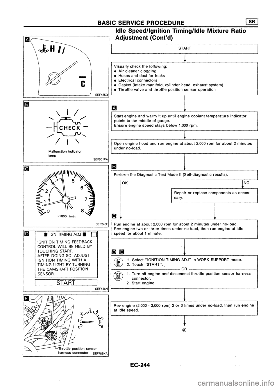
Visually checkthefollowing:
• Air cleaner clogging
• Hoses andduct forleaks
• Electrical connectors
• Gasket (intakemanifold, cylinderhead,exhaust system)
• Throttle valveandthrottle position sensoroperation
m
Start engine andwarm itup until engine coolant temperature indicator
points tothe middle ofgauge.
Ensure enginespeedstaysbelow 1,000rpm.
1
Open engine hoodandrunengine atabout 2,000rpmforabout 2minutes
under no-load.
Ii]
Perform theDiagnostic TestMode
1\
(Self-diagnostic results).
OK ~NG
Repair orreplace components asneces-
sary.
[!J
Run engine atabout 2,000rpmforabout 2minutes underno-load.
Rev engine twoorthree times under no-load, thenrunengine atidle
speed forabout 1minute .
li]1!I
00
1.
Select "IGNITION TIMINGADJ"inWORK SUPPORT mode.
2. Touch "START" .
.
OR
00
1.
Turn offengine anddisconnect throttleposition sensorharness
connector.
2. Start engine.
Rev engine (2,000-3,000 rpm)2or 3times under no-load, thenrunengine
at idle speed.
t
Throttle position sensor
harness connector SEF785KASEF051PA
BASIC
SERVICE PROCEDURE Em
Idle Speedllgnition TiminglldleMixtureRatio
Adjustment (Cont'd)
SEF248F
SEF455Q
Malfunction indicator
lamp \
I/
'~,,/
- CHECK-
,,/
........
/ I\
Ii] •IGN TIMING ADJ.
D
IGNITION TIMINGFEEDBACK
CONTROL WILLBEHELD BY
TOUCHING START.
AFTER DOING SO,ADJUST
IGNITION TIMINGWITHA
TIMING LIGHTBYTURNING
THE CAMSHAFT POSITION
SENSOR.
I
START
I
SEF546N
EC-244
Page 964 of 1701
AEC804
•
Ii
L
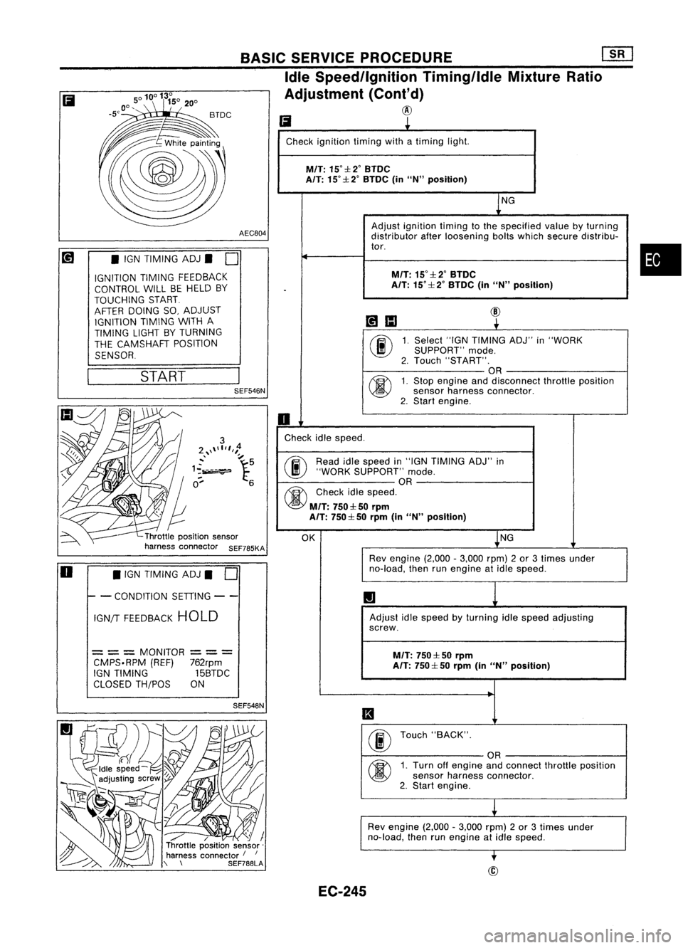
Check ignition timingwithatiming light.
M/T:
15°::l:2°BTDC
A/T: 15°::l: 2°BTDC (inUN" position)
NG
Adjust ignition timingtothe specified valuebyturning
distributor afterloosening boltswhich secure distribu-
tor.
M/T:
15°::l:2°BTDC
.
A/T:
15°::l: 2°BTDC (inUN" position)
~IIJ
@
~
00
1.
Select
"IGNTIMING ADJ"in"WORK
SUPPORT" mode.
2. Touch "START".
OR
@
1.
Stop engine anddisconnect throttleposition
sensor harness connector.
2. Start engine.
0
Check idlespeed.
@ Read
idlespeed in"IGN TIMING ADJ"in
"WORK SUPPORT" mode.
OR
@
Checkidlespeed.
M/T:
750::l: 50rprn
A/T: 750::l: 50rprn (inUN" position)
OK NG
Rev engine (2,000-3,000 rpm)2or 3times under
no-load, thenrunengine atidle speed.
1.1
Adjust idlespeed byturning idlespeed adjusting
screw.
M/T:
750::l: 50rpm
A/T: 750::l: 50rprn (inUN" position)
II
00
Touch
"BACK".
OR
@
1.
Turn offengine andconnect throttleposition
sensor harness connector.
2. Start engine.
L
Rev engine (2,000-3,000 rpm)2or 3times under
no-load, thenrunengine atidle speed.
-.
BASIC
SERVICE PROCEDURE
[]K]
Idle Speed/Ignition Timing/IdleMixtureRatio
Adjustment (Cont'd)
@
SEF548N
/ / I
Throttle position sensor-
harness connector /
I
\ \ SEF788LASEF546N
START
•
IGN TIMING ADJ.
0
IGNITION TIMINGFEEDBACK
CONTROL WILLBEHELD BY
TOUCHING START
AFTER DOING SO,ADJUST
IGNITION TIMINGWITHA
TIMING LIGHTBYTURNING
THE CAMSHAFT POSITION
SENSOR
= ==
MONITOR
==
=
CMPS.RPM (REF)762rpm
IGN TIMING 15BTDC
CLOSED TH/POS ON
Ii
o •
IGN TIMING ADJ.
0
I- -
CONDITION SETIING--
IGN/T FEEDBACK HOLD
EC-245
Page 975 of 1701
ON-BOARDDIAGNOSTIC SYSTEMDESCRIPTION
CONSULT (Cont'd)
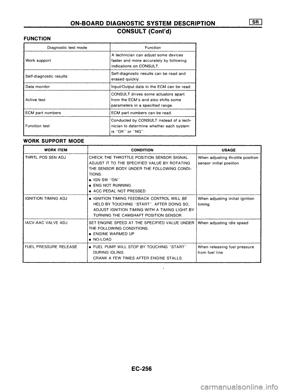
FUNCTION
Diagnostictestmode Function
A technician canadjust somedevices
Work support
fasterandmore accurately byfollowing
indications onCONSULT.
Self-diagnostic results Self-diagnostic
resultscanberead and
erased quickly.
Data monitor
Input/Outputdatainthe ECM canberead.
CONSULT drivessomeactuators apart
Active test fromtheECM's andalso shifts some
parameters inaspecified range.
ECM partnumbers
ECMpartnumbers canberead.
Conducted byCONSULT insteadofatech-
Function test
niciantodetermine whethereachsystem
is "OK" or"NG".
WORK SUPPORT MODE
WORK ITEM
CONDITION USAGE
THRTL POSSENADJ
CHECKTHETHROTTLE POSITIONSENSORSIGNAL. Whenadjusting throttleposition
ADJUST ITTO THE SPECIFIED VALUEBYROTATING
sensorinitialposition
THE SENSOR BODYUNDER THEFOLLOWING CONDI-
TIONS .
• IGN SW"ON"
• ENG NOTRUNNING
• ACC PEDAL NOTPRESSED
IGNITION TIMINGADJ
•IGNITION TIMINGFEEDBACK CONTROLWILLBE
Whenadjusting initialignition
HELD BYTOUCHING "START".AFTERDOINGSO, timing
ADJUST IGNITION TIMINGWITHATIMING LIGHTBY
TURNING THECAMSHAFT POSITIONSENSOR.
IACV-AAC VALVEADJ
SETENGINE SPEEDATTHE SPECIFIED VALUEUNDER
Whenadjusting idlespeed
THE FOLLOWING CONDITIONS.
• ENGINE WARMED UP
• NO-LOAD
FUEL PRESSURE RELEASE •FUEL PUMP WILLSTOP BYTOUCHING "START"
Whenreleasing fuelpressure
DURING IDLING.
fromfuelline
CRANK AFEW TIMES AFTER ENGINE STALLS
EC-256
Page 976 of 1701
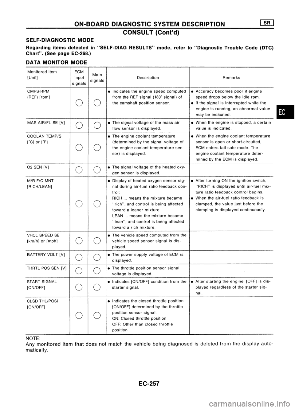
ON-BOARDDIAGNOSTIC SYSTEMDESCRIPTION
CONSULT (Cont'd)
SELF-DIAGNOSTIC MODE
Regarding itemsdetected in"SELF-DiAG RESULTS"mode,referto"Diagnostic TroubleCode(DTC)
Chart". (Seepage EC-268.)
DATA MONITOR MODE
Monitored item ECM
Main
[Unit] input
signals Description
Remarks
signals
CMPS.RPM •Indicates theengine speedcomputed •
Accuracy becomespoorifengine
(REF) [rpm] fromtheREF signal (180'signal) of speeddropsbelow theidle rpm.
0 0
the
camshaft positionsensor. •
Ifthe signal isinterrupted whilethe
engine isrunning, anabnormal value
may beindicated .
MAS AIR/FL SE[V]
0 0
•
The sig~al voltage ofthe mass air •
When theengine isstopped, acertain
flow sensor isdisplayed. valueisindicated .
COOLAN TEMP/S •
The engine coolant temperature •
When theengine coolant temperature
rOC] orrF] (determined
bythe signal voltage ofsensor
isopen orshort-circuited,
0 0
the
engine coolant temperature sen-ECMenters fail-safe mode.The
sor) isdisplayed. engine
coolant temperature deter-
mined bythe ECM isdisplayed .
02
SEN [V]
00
•
The signal voltage ofthe heated oxy-
gen sensor isdisplayed.
M/R F/CMNT •
Display ofheated oxygen sensorsig-•
After turning ONthe ignition switch,
[RICH/LEAN] nal
during air-fuel ratiofeedback con-"RICH"
isdisplayed untilair-fuel mix-
trol: ture
ratio feedback controlbegins.
RICH ...means themixture became •
When theair-fuel ratiofeedback is
0 0
"rich",
andcontrol isbeing affected clamped,
thevalue justbefore the
toward aleaner mixture. clamping
isdisplayed continuously.
LEAN ...means themixture became
"lean", andcontrol isbeing affected
toward arich mixture .
VHCL SPEED SE •
The vehicle speedcomputed fromthe
[km/h] or[mph]
00
vehicle
speedsensor signalisdis-
played .
SA TTERY VOLT[V]
0 0
•
The power supply voltage ofECM is
displayed .
THRTL POSSEN [V]
0 0
•
The throttle position sensorsignal
voltage isdisplayed.
START SIGNAL •
Indicates [ON/OFF] conditionfromthe•
After starting theengine, [OFF]isdis-
[ON/OFF]
00
starter
signal. played
regardless ofthe starter sig-
nal.
CLSD THLIPOSI •
Indicates theclosed throttle position
[ON/OFF] [ON/OFF]
determined bythe throttle
0 0
position
sensorsignal.
ON: Closed throttle position
OFF: Other thanclosed throttle
position
NOTE:
Any monitored itemthatdoes notmatch thevehicle beingdiagnosed isdeleted fromthedisplay auto-
matically.
EC-257
•
Page 977 of 1701
![NISSAN ALMERA N15 1995 Service Manual ON-BOARDDIAGNOSTIC SYSTEMDESCRIPTION
CONSULT (Conl'd)
Monitored item ECM
Main
[Unit] input
signals Description
Remarks
signals
AIR COND SIG •Indicates [ON/OFF] conditionofthe
[ON/OFF]
00
air
NISSAN ALMERA N15 1995 Service Manual ON-BOARDDIAGNOSTIC SYSTEMDESCRIPTION
CONSULT (Conl'd)
Monitored item ECM
Main
[Unit] input
signals Description
Remarks
signals
AIR COND SIG •Indicates [ON/OFF] conditionofthe
[ON/OFF]
00
air](/manual-img/5/57349/w960_57349-976.png)
ON-BOARDDIAGNOSTIC SYSTEMDESCRIPTION
CONSULT (Conl'd)
Monitored item ECM
Main
[Unit] input
signals Description
Remarks
signals
AIR COND SIG •Indicates [ON/OFF] conditionofthe
[ON/OFF]
00
air
conditioner switchasdetermined
by the airconditioning signal.
PIN POSI SW
00
•
Indicates [ON/OFF] conditionfromthe
[ON/OFF] park/neutralpositionswitchsignal.
PW/ST SIGNAL •Indicates [ON/OFF] conditionofthe
[ON/OFF]
00
power
steering oilpressure switch
determined bythe power steering oil
pressure signal.
INJ PULSE [msec]
0
•
Indicates theactual fuelinjection •
When theengine isstopped, acertain
pulse widthcompensated byECM computedvalueisindicated.
according tothe input signals.
IGN TIMING [BTDC]
0
•
Indicates theignition timingcomputed
by ECM according tothe input sig-
nals.
IACV-AACIV
[%]
•Indicates theidle aircontrol valve
0
(AAC
valve) control valuecomputed
by ECM according tothe input sig-
nals.
A/F ALPHA [%J •Indicates themean valueofthe air- •When theengine isstopped, acertain
0
fuel
ratio feedback correction factor valueisindicated.
per cycle. •This dataalsoincludes thedata for
the air-fuel ratiolearning control.
AIR COND RLY •Indicates theairconditioner relay
[ON/OFF]
0
control
condition (determined byECM
according tothe input signal).
FUEL PUMP RLY •Indicates thefuel pump relaycontrol
[ON/OFFJ
0
condition
determined byECM accord-
ing tothe input signals.
COOLING FAN
•Indicates thecontrol condition ofthe
[HI/LOW/OFFJ coolingfans(determined byECM
0
according
tothe input signal).
HI ...High speed operation
LOW ...Low speed operation
OFF ...Stopped
EGRC SOLIV •Indicates thecontrol condition ofthe
[ON/OFFJ EGR
valve
&
EVAP canister Purge
control solenoid valve(determined by
0
ECM
according tothe input signal).
ON ...EGR andEVAP canister purge
operation cut-off
OFF ...EGR andEVAP canister purge
operation notcut-off
VOLTAGE •Voltage measured bythe voltage
[V] probe.
PULSE •Pulse width, frequency orduty cycle •Only "#"isdisplayed ifitem is
[msec] or[Hz] or
measuredbythe pulse probe. unabletobe measured.
[%]
•Figures with"#"s aretemporary
ones. Theyarethesame figures as
an actual pieceofdata which wasjust
previously measured.
EC-258
Page 978 of 1701

ON-BOARDDIAGNOSTIC SYSTEMDESCRIPTION
CONSULT (Conl'd)
ACTIVE TESTMODE
TEST ITEM CONDITION JUDGEMENTCHECKITEM(REMEDY)
• Engine: Returntothe original
•Harness andconnector
FUEL INJECTION trouble
condition
Iftrouble symptom disappears,
•Fuel injectors
• Change theamount offuel
seeCHECK ITEM.
•Heated oxygen sensor
injection usingCONSULT .
• Engine: Afterwarming up,idle
IACV-AACIV the
engine.
Enginespeedchanges according •Harness andconnector
OPENING •
Change theIACV-AAC valve
tothe opening percent. •
IACV-AAC valve
opening percentusingCON-
SULT.
• Engine: Returntothe original
•Harness andconnector
ENG COOLANT trouble
condition
Iftrouble symptom disappears, •
Engine coolant temperature
• Change theengine coolant
.
TEMP see
CHECK ITEM. sensor
temperature indicationusing
•Fuel injectors
CONSULT .
• Engine: Returntothe original
trouble condition
Iftrouble symptom disappears,
IGNITION TIMING•Timing light:Set •
Adjust initialignition timing
• Retard theignition timingusingsee
CHECK ITEM.
CONSULT.
• Engine: Afterwarming up,idle •
Harness andconnector
the engine. •
Compression
POWER
•
AIC
switch "OFF"
Enginerunsrough ordies. •
Injectors
BALANCE •
Shift lever "N" •
Power transistor
• Cut offeach injector signalone •
Spark plugs
at atime using CONSULT . •
Ignition coils
• Ignition switch:ON
•Harness andconnector
COOLING FAN•
Turn thecooling fan"ON" andCooling
fanmoves andstops.
•Cooling fanmotor
"OFF" usingCONSULT .
• Ignition switch:ON(Engine
FUEL PUMP stopped)
Fuelpump relaymakes theoper- •
Harness andconnector
RELAY •
Turn thefuel pump relay"ON"
atingsound. •
Fuel pump relay
and "OFF" usingCONSULT
and listen tooperating sound.
EGRC •
Ignition switch:ON
• Turn solenoid valve"ON"and Solenoid
valvemakes anoperat- •
Harness andconnector
SOLENOID "OFF"withtheCONSULT andingsound. •
Solenoid valve
VALVE listentooperating sound.
SELF-LEARNING •
In this test, thecoefficient ofself-learning controlmixture ratioreturns tothe original coefficient by
CONT touching
"CLEAR" onthe screen.
EC-259
•