1995 NISSAN ALMERA N15 Idle speed control
[x] Cancel search: Idle speed controlPage 794 of 1701
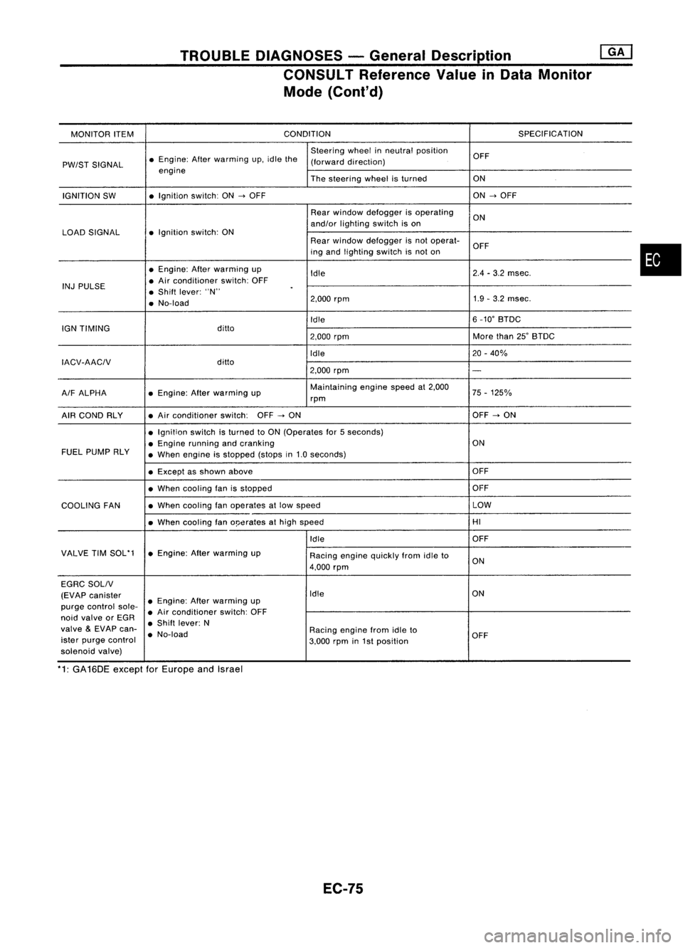
TROUBLEDIAGNOSES -General Description @KJ
CONSULT Reference ValueinData Monitor
Mode (Cont'd)
MONITOR ITEM CONDITION
SPECIFICATION
Steering wheelinneutral position
OFF
PW/ST SIGNAL •
Engine: Afterwarming up.idle the
(forward direction)
engine Thesteering wheelisturned ON
IGNITION SW •
Ignition switch:ON
-->
OFF ON
-->
OFF
Rear window defogger isoperating
ON
and/or lighting switchison
LOAD SIGNAL •
Ignition switch:ON
Rearwindow defogger isnot operat-
OFF
ing and lighting switchisnot on
• Engine: Afterwarming up
Idle 2.4
-3.2 msec.
INJ PULSE •
Air conditioner switch:OFF
• Shift lever: "N"
.
• No-load 2.000
rpm 1.9
-3.2 msec.
Idle 6
_10' BTDC
IGN TIMING ditto
2.000rpm More
than25'BTDC
Idle 20-40%
IACV-AACIV ditto
2.000rpm
-
A/F ALPHA •
Engine: Afterwarming up Maintaining
enginespeedat2.000
75-125%
rpm
AIR COND RLY •
Air conditioner switch:OFF
-->
ON OFF
-->
ON
• Ignition switchisturned toON (Operates for5seconds)
• Engine running andcranking ON
FUEL PUMP RLY
•When engine isstopped (stopsin1.0 seconds)
• Except asshown above OFF
• When cooling fanisstopped OFF
COOLING FAN •
When cooling fanoperates atlow speed LOW
• When cooling fano!Jerates athigh speed HI
Idle OFF
VALVE TIMSOL'1 •Engine: Afterwarming up
Racingenginequickly fromidleto
4.000 rpm ON
EGRC SOLIV
(EVAP canister Idle
ON
purge control sole-•
Engine: Afterwarming up
• Air conditioner switch:OFF
noid valve orEGR
•Shift lever: N
valve
&
EVAP can-
•No-load Racing
enginefromidleto
ister purge control
3.000rpmin1st position OFF
solenoid valve)
*1: GA16DE exceptforEurope andIsrael
EC-75
•
Page 801 of 1701
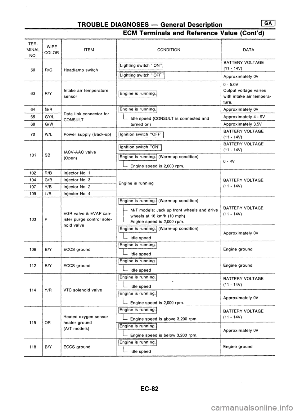
TROUBLEDIAGNOSES -General Description ~
ECM Terminals andReference Value(Conl'd)
TER- WIRE
MINAL COLOR ITEM
CONDITION DATA
NO.
ILightingswitch"ON"I BATTERY
VOLTAGE
60
RIG
Headlamp switch (11
-14V)
ILighting switch"OFF"I
ApproximatelyOV
0- 5.0V
63 RIY Intake
airtemperature
I
Engine isrunning.
I
Output
voltage varies
sensor with
intake airtempera-
ture.
64 GIR
I
Engine isrunning.
I
Approximately
OV
65 GY/L Data
linkconnector for
L
Idle speed (CONSULT isconnected andApproximately
4-9V
CONSULT
68
GIW
turnedon) Approximately
3.5V
I,gnition switch"OFF"
I
BATTERY
VOLTAGE
70
W/L
Powersupply (Back-up)
(11-14V)
Ilgnition switch"ON"I BA
TTERY VOLTAGE
IACV-AAC valve (11
-14V)
101 SS
(Open)
I
Engine isrunning.
I
(Warm-up condition)
L
Engine speedis2,000 rpm. 0-
4V
102 RIB Injector
No.1
104
GIS
InjectorNo.3
BATTERYVOLTAGE
107 YIB InjectorNo.2 Engine
isrunning
(11-14V)
109 LIB Injector
No.4
IEngineisrunning.
I
(Warm-up condition)
~ MIT
models: Jackupfront wheels anddrive BATTERY
VOLTAGE
EGR valve
&
EVAP can-
L
wheels at16 kmlh (10mph) (11
-14V)
103 P
.isterpurge control sole-
Enginespeedis2,000 rpm.
noid valve
IEngineisrunning.
I
(Warm-up condition)
L
Idle speed Approximately
OV
106 BIY ECCSground
I
Engine isrunning.
I
Engineground
L
Idle speed
112 BIY ECCS
ground
I
Engine isrunning.
I
Engineground
L
Idle speed
I Engine isrunning.
I
BATTERYVOLTAGE
L
Idle speed
.
(11-14V)
114 YIR VTCsolenoid valve
I
Engine isrunning.
I
L
Engine speedis2,000 rpm. Approximately
OV
IEngine isrunning.
I
BATTERYVOLTAGE
Heated oxygen sensor
L
Engine speedisabove 3,200rpm. (11
-14V)
115 OR heaterground
IEngine isrunning.
I
(A/T models)
ApproximatelyOV
L
Engine speedisbelow 3,200rpm.
118 SlY ECCS
ground
I
Engine isrunning.
I
Engineground
L
Idle speed
EC-82
Page 805 of 1701
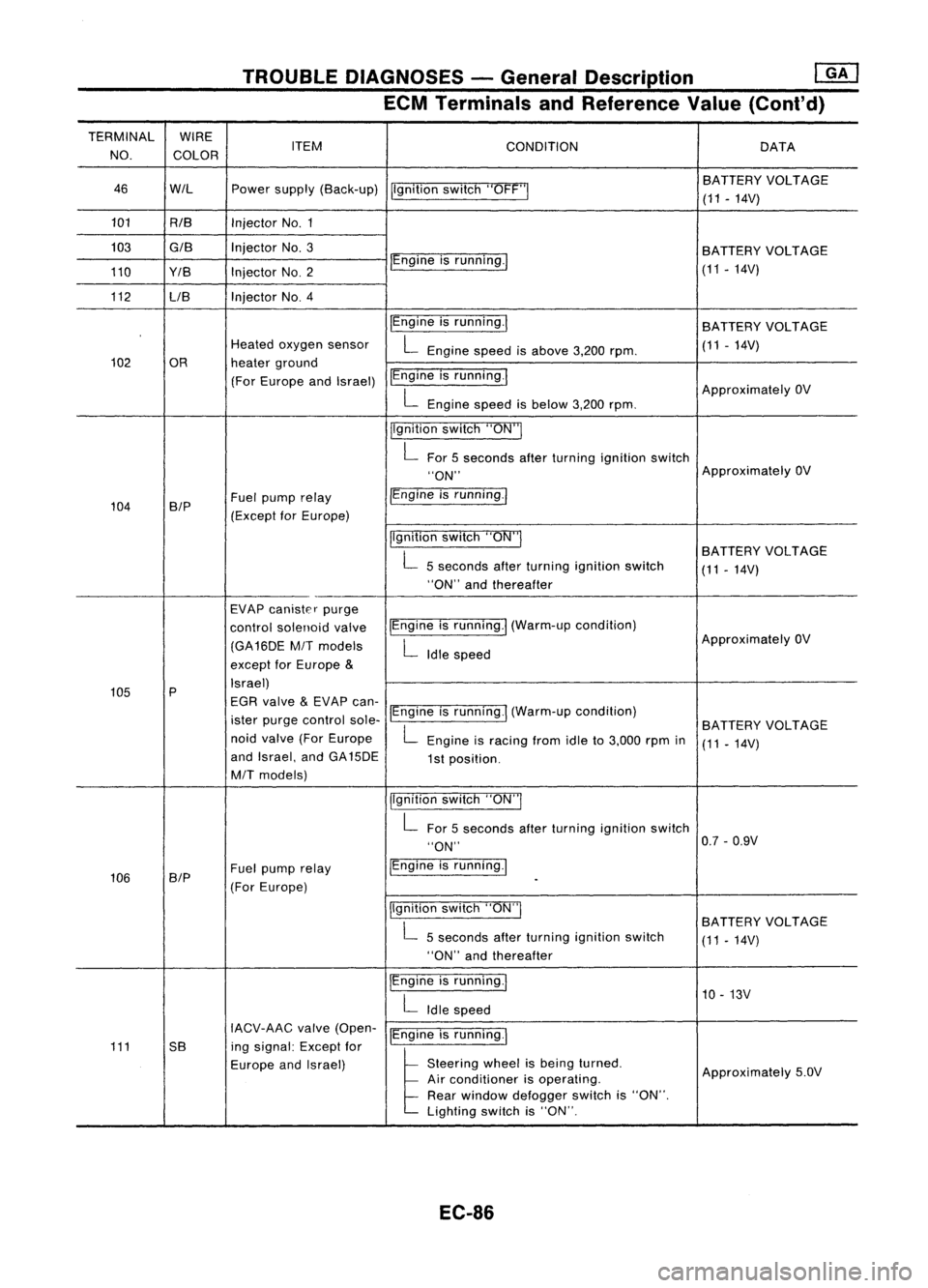
TROUBLEDIAGNOSES -General Description
mJ
ECM Terminals andReference Value(Cont'd)
TERMINAL WIRE
NO. COLOR ITEM
CONDITION DATA
46 WIL Powersupply (Back-up)
Ilgnitionswitch"OFF'" BA
TTERY VOLTAGE
(11 -14V)
101 RIB InjectorNo.1
103
GIB
InjectorNo.3
BATTERYVOLTAGE
110 Y/B InjectorNO.2 IEngine
isrunning./
(11-14V)
112 LIB Injector
NO.4
IEngineisrunning.1
BATTERY VOLTAGE
Heated oxygen sensor
L
Engine speedisabove 3,200rpm. (11
-14V)
102 OR heaterground
(For Europe andIsrael) IEngine
isrunning.1
ApproximatelyOV
L
Engine speedisbelow 3,200rpm.
jlgnition switch"ON"I
L
For 5seconds afterturning ignition switch
"ON" Approximately
OV
104 B/P Fuel
pump relay /Engine
isrunning.1
(Except forEurope)
Ilgnitionswitch"ON"I
BATTERYVOLTAGE
L
5seconds afterturning ignition switch
(11-14V)
"ON" andthereafter
EVAP canister purge
control solenoid valveIEngine
isrunning.1 (Warm-up condition)
(GA16DE
MIT
models
L
Idle speed Approximately
OV
except forEurope
&
105 P Israel)
EGR valve
&
EVAP can-
ister purge control sole-IEngine
isrunning.1 (Warm-up condition)
BATTERYVOLTAGE
noid valve (ForEurope
L
Engine isracing fromidleto3,000 rpmin
(11-14V)
and Israel, andGA15DE
1st position.
MIT
models)
jlgnitionswitch"ON"I
L
For 5seconds afterturning ignition switch
"ON" 0.7
-0.9V
106 SIP Fuel
pump relay IEngine
isrunning.1
(For Europe)
-
Ilgnition switch"ON"I
BATTERYVOLTAGE
L
5seconds afterturning ignition switch
(11-14V)
"ON" andthereafter
IEngine isrunning.1
10-13V
L
Idle speed
IACV-AAC valve(Open-
IEngineisrunning.1
111 5B ingsignal: Exceptfor
Europe andIsrael)
l
51.."" wheel
t,
be'" I,med
Approximately5.0V
Air conditioner isoperating.
Rear window defogger switchis"ON".
Lighting switchis"ON".
EC-86
Page 847 of 1701
TROUBLEDIAGNOSIS FORNON-DETECTABLE ITEMS
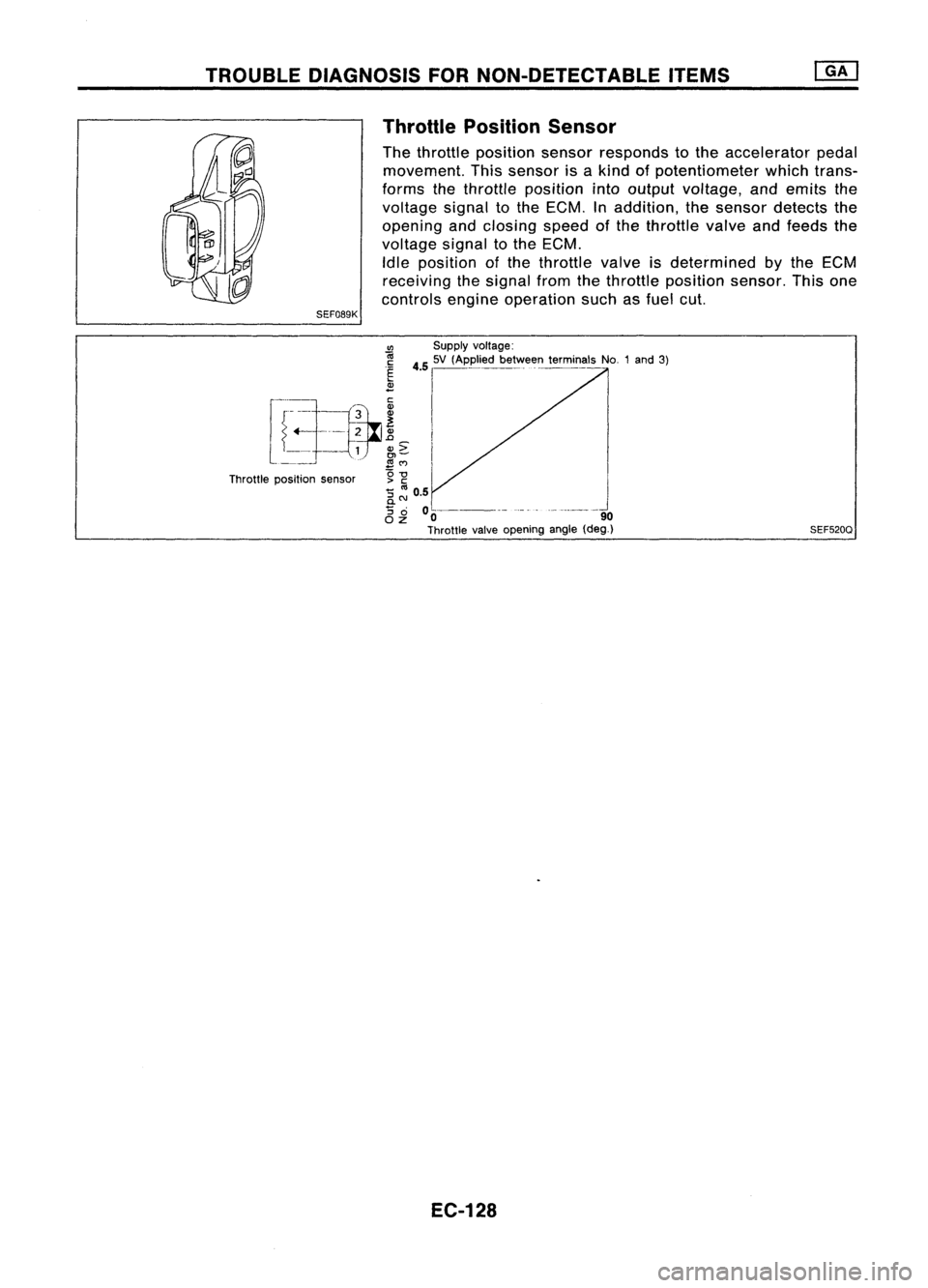
Throttle Position Sensor
The throttle position sensorresponds tothe accelerator pedal
movement. Thissensor isakind ofpotentiometer whichtrans-
forms thethrottle position intooutput voltage, andemits the
voltage signaltothe ECM. Inaddition, thesensor detects the
opening andclosing speedofthe throttle valveandfeeds the
voltage signaltothe ECM.
Idle position ofthe throttle valveisdetermined
by
the ECM
receiving thesignal fromthethrottle position sensor.Thisone
controls engineoperation suchasfuel cut.
SEF089K
CIl
Supplyvoltage:
r
-i.~h __
~3_
i
45
I
'V ,Appl.' b....
ffi
t~miMI,
No1,,'
31
~_ =r--=-tfr ~
I
l ~
1
N~
I
Throttle position sensor g
-g
'5 ::: 0.5
0-
'5
0 0----- -_.- --------_.
OZ 0 90
Throttle valveopening angle(deg_)
EC-128 SEF520Q
Page 862 of 1701
•
INSPECTION END
Check thefollowing.
• Harness connectors
@,@or@,
@
• Harness connectors
@,CillD
• Harness foropen or
short between injector
and ignition switch
If NG, repair harness or
connectors.
OK
NG
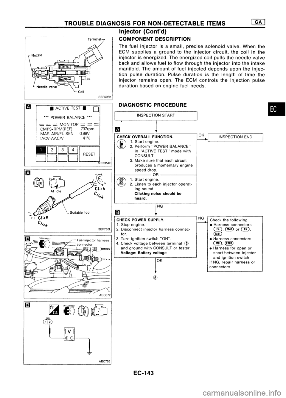
DIAGNOSTIC
PROCEDURE
INSPECTION START
CHECK OVERALL FUNCTION.
(F.I\
1.Start engine.
~ 2.Perform "POWER BALANCE"
in "ACTIVE TEST"modewith
CONSULT.
3. Make surethateach circuit
produces amomentary engine
speed drop.
OR
fff\
1.Start engine.
~ 2.Listen toeach injector operat-
ing sound.
Clicking noiseshould be
heard.
CHECK POWER SUPPLY.
1. Stop engine.
2. Disconnect injectorharness connec-
tor.
3. Turn ignition switch"ON".
4. Check voltage between terminal @
and ground withCONSULT ortester.
Voltage: Batteryvoltage
AEC872
SEF730L
/~~
Click
Ct.
'~.+
Fuel injector harness
connector
II
TROUBLE
DIAGNOSIS FORNON-DETECTABLE ITEMS
Injector (Cont'd)
COMPONENT DESCRIPTION
The fuel injector isasmall, precise solenoid valve.Whenthe
ECM supplies aground tothe injector circuit,thecoil
in
the
injector isenergized. Theenergized coilpulls theneedle valve
back andallows fueltoflow through theinjector intotheintake
manifold. Theamount offuel injected depends upontheinjec-
tion pulse duration. Pulseduration isthe length oftime the
injector remains open.TheECM controls theinjection pulse
duration basedonengine fuelneeds.
SEF596K
• ACTIVE TEST.
D
••• POWER BALANCE •••
= ==
MONITOR
=
==
CMPS.RPM(REF) 737rpm
MAS AIR/FL SEN098V
IACV-AAC/V 41%
110Q]Q]~
DDDDc:J
MEF354F
~7~
~ \)drJ
At idle
--
/ I
AEC755EC-143
Page 869 of 1701
TROUBLEDIAGNOSIS FORNON-DETECTABLE ITEMS
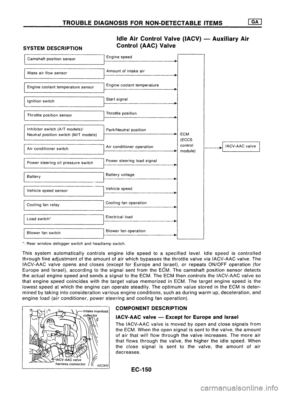
SYSTEM DESCRIPTION Idle
AirControl Valve(IACV) -Auxiliary Air
Control (AAC)Valve
Camshaft positionsensor Engine
speed
I
Mass
airflow sensor Amount
ofintake air
I
Engine coolant temperature sensor Engine
coolant temperature
~
I
Ignition switch Start
signal
I
Throttle positionsensor Throttle
position
~
I
Inhibitor switch(A/Tmodels)/
Park/Neutralposition
Neutral position switch(M/Tmodels) ECM
(ECCS
Air conditioner operation control
!
IACV-AAC valve
I
Air conditioner switch
module)
Power steering oilpressure switch Power
steering loadsignal
I
Battery
~
Battery voltage
Vehicle speedsensor Vehicle
speed
Cooling fanrelay Cooling
fanoperation
Load switch' Electrical
load
Blower fanswitch Blower
fanoperation
': Rear window defogger switchandheadlamp switch.
This system automatically controlsengineidlespeed toaspecified level.Idlespeed iscontrolled
through fineadjustment ofthe amount ofair which bypasses thethrottle valveviaIACV-AAC valve.The
IACV-AAC valveopens andcloses (except forEurope andIsrael), orrepeats ON/OFF operation (for
Europe andIsrael), according tothe signal sentfrom theECM. Thecamshaft positionsensordetects
the actual engine speedandsends asignal tothe ECM. TheECM thencontrols theIACV-AAC valveso
that engine speedcoincides withthetarget valuememorized inECM. Thetarget engine speedisthe
lowest speedatwhich theengine canoperate steadily. Theoptimum valuestored inthe ECM isdeter-
mined bytaking intoconsideration variousengineconditions, suchasduring warmup,deceleration, and
engine load(airconditioner, powersteering andcooling fanoperation).
COMPONENT DESCRIPTION
IACV-AAC valve-Except forEurope andIsrael
The IACV-AAC valveismoved byopen andclose signals from
the ECM. When theopen signal issent tothe valve, theamount
of air that willflow through thevalve increases. Themore air
that flows through thevalve, thehigher theidle speed. When
the close signal issent tothe valve. theamount ofair
decreases.
EC-150
Page 870 of 1701
TROUBLEDIAGNOSIS FORNON-DETECTABLE ITEMS~
Idle AirControl Valve(IACV) -Auxiliary Air
Control (AAC)Valve(Cont'd)
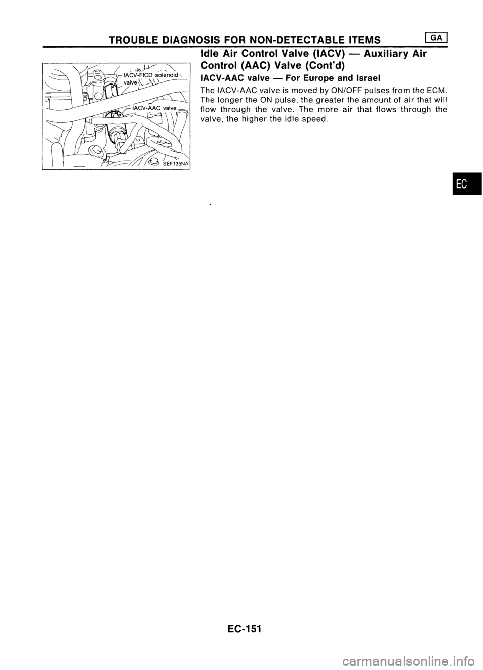
IACV-AAC valve-For Europe andIsrael
The IACV-AAC valveismoved
by
ON/OFF pulsesfromtheECM.
The longer theON pulse, thegreater theamount ofair that will
flow through thevalve. Themore airthat flows through the
valve, thehigher theidle speed.
EC-151
•
Page 873 of 1701
Repairharness orcon-
nectors. INSPECTION
END
Check thefollowing.
• Harness connectors
QD,@orQD,
@
• 10A fuse
• Harness foropen or
short between IACV-AAC
valve andfuse
If NG, repair harness or
connectors.
NG OK
NG
OK
INSPECTION
START
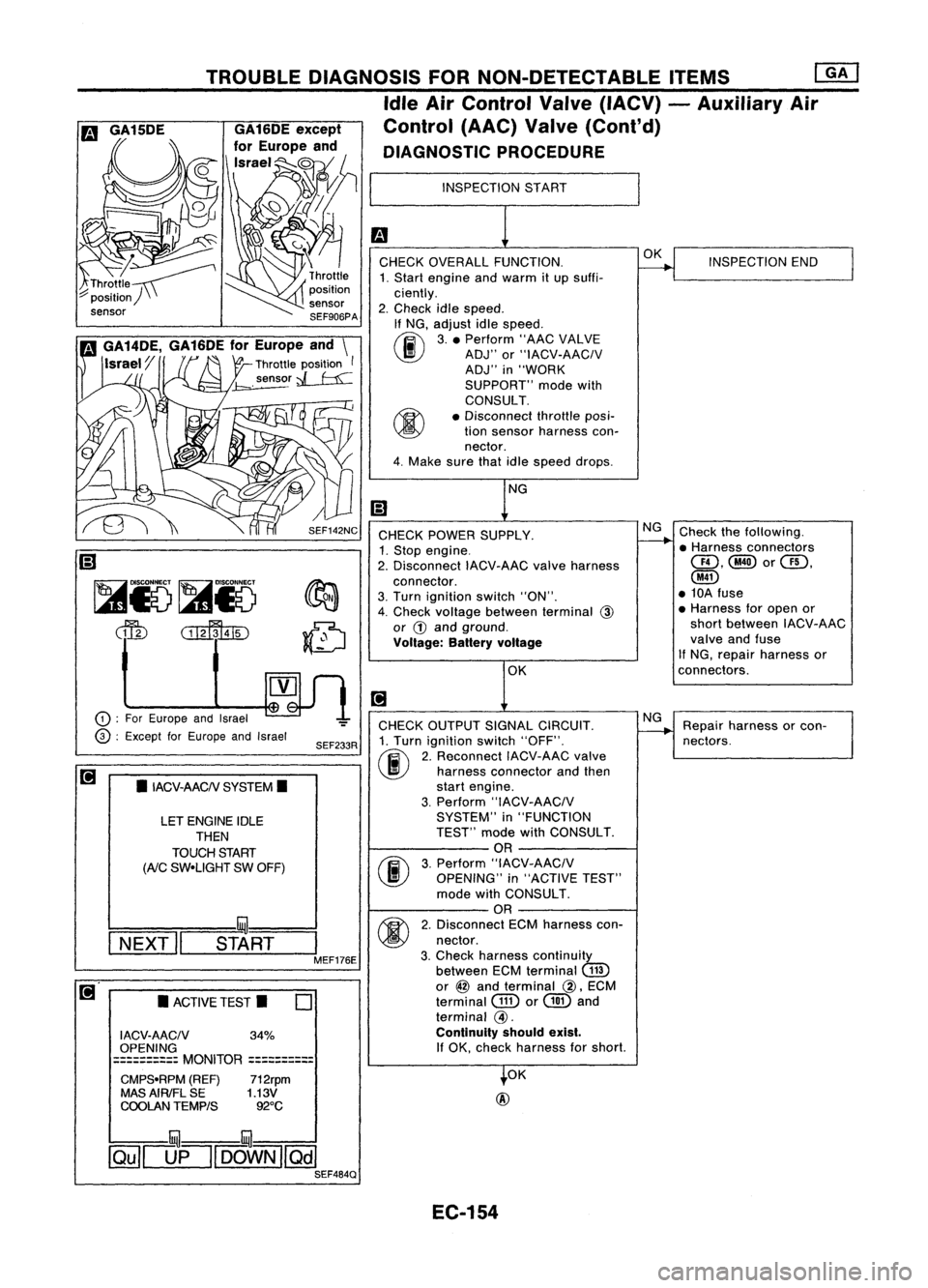
CHECK OVERALL FUNCTION.
1. Start engine andwarm itup suffi-
ciently.
2. Check idlespeed.
If NG, adjust idlespeed.
~ 3.• Perform "AACVALVE
~ ADJ"or"IACV-AACIV
ADJ" in"WORK
SUPPORT" modewith
CONSULT.
• Disconnect throttleposi-
tion sensor harness con-
nector.
4. Make surethatidlespeed drops.
OK
@
CHECK
POWER SUPPLY.
1. Stop engine.
2. Disconnect IACV-AACvalveharness
connector.
3. Turn ignition switch"ON".
4. Check voltage between terminal
@
or
G)
and ground.
Voltage: Batteryvoltage
CHECK OUTPUT SIGNALCIRCUIT.
1. Turn ignition switch"OFF".
(ij\
2.Reconnect IACV-AACvalve
~ harnessconnector andthen
start engine.
3. Perform "IACV-AACIV
SYSTEM" in"FUNCTION
TEST" modewithCONSULT.
OR
(F.I\
3.Perform "IACV-AACIV
~ OPENING" in"ACTIVE TEST"
mode withCONSULT.
OR
M
2.Disconnect ECMharness con-
~ nectar.
3. Check harness continuity
between ECMterminal
(ill)
or
@
and terminal
@,
ECM
terminal
GID
or
@
and
terminal
@.
Continuity shouldexist.
If
OK, check harness forshort.
SEF233R
SEF142NC
o
•
ACTIVE TEST.
LET
ENGINE IDLE
THEN
TOUCH START
(AiC
SW-UGHT SWOFF)
•
IACV-AACN SYSTEM.
I ACV-AACN 34%
OPENING
==========
MONITOR
==========
CMPS-RPM (REF)712rpm
MAS AIRIFL SE 1.13V
COOLAN TEMPtS 92°C
TROUBLE
DIAGNOSIS FORNON-DETECTABLE ITEMS
ffiJ
Idle AirControl Valve(IACV) -Auxiliary Air
Control (AAC)Valve(Cont'd)
DIAGNOSTIC PROCEDURE
!:::=====mul===
I
NEXT" START
I
MEF176E
CD
:
For Europe andIsrael
@ :
Except forEurope andIsrael
~
Ii)
~i5~i5
dfu
CillffuID
illU--illU
~[]fl[OOWN][Qill SEF484Q
EC-154