1995 NISSAN ALMERA N15 Idle speed control
[x] Cancel search: Idle speed controlPage 748 of 1701
EVAPORATIVEEMISSIONSYSTEM
•
SEF126R
EVAP
canister
'1
EVAP canister
purge control
solenoid valve
or
'2 EGR valve
&
EVAP canister
purge control
solenoid
valve To
EGR
I
valve
I
,
I
1
1
I
I
I
Vacuum :
signal line I
I
I
I
I
I
I
-- -- --- -- ------ __....J
r---
------- -------- ---------,
Fuel fillercap
with vacuum
relief valve
------------,
I
I
I
I
I
I
I
I
I
I
I
'-
Throttle
valve~
I
Fuel check valve
Intake
manifold
'1 :GA 16DE M/Tmodels exceptforEurope,
Israel andAustralia
'2 :For Europe, IsraelandAustralia,
and GA15DE
M/T
models
~ :GA 15, 16DE AlTmodels exceptfor
Europe, IsraelandAustralia
.. :Air
Q :
Fuel vapor
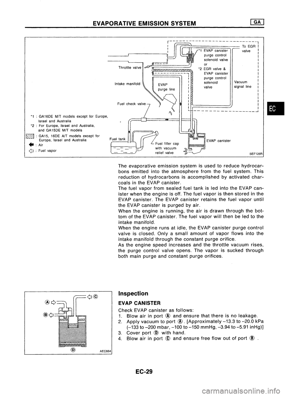
Theevaporative emissionsystemisused toreduce hydrocar-
bons emitted intotheatmosphere fromthefuel system. This
reduction ofhydrocarbons isaccomplished byactivated char-
coals inthe EVAP canister.
The fuelvapor fromsealed fueltank isled into theEVAP can-
ister when theengine isoff. The fuelvapor isthen stored inthe
EVAP canister. TheEVAP canister retainsthefuel vapor until
the EVAP canister ispurged byair.
When theengine isrunning, theairisdrawn through thebot-
tom ofthe EVAP canister. Thefuel vapor willthen beled tothe
intake manifold.
When theengine runsatidle, theEVAP canister purgecontrol
valve isclosed. Onlyasmall amount ofvapor flowsintothe
intake manifold throughtheconstant purgeorifice.
As the engine speedincreases andthethrottle vacuum rises,
the purge control valveopens. Thevapor issucked through
both main purge andconstant purgeorifices.
@Q
@
AEC664Inspection
EVAP CANISTER
Check EVAPcanister asfollows:
1. Blow airinport
@
and ensure thatthere isno leakage.
2.
Apply vacuum toport
@.
[Approximately
-13.3
to
-20.0
kPa
(-133
to
-200
mbar,
-100
to
-150
mmHg,
-3.94
to
-5.91
inHg)]
3. Cover port
CID
with hand.
4. Blow airinport
@
and ensure freeflow outofport
CID.
EC-29
Page 754 of 1701

BASICSERVICE PROCEDURE
Idle Speedllgnition TiminglldleMixtureRatio
Adjustment
PREPARATION
• Make surethatthefollowing partsarein
good order.
(1) Battery
(2) Ignition system
(3) Engine oiland coolant levels
(4) Fuses
(5) ECM harness connector
(6) Vacuum hoses
(7) Airintake system
(Oil filler cap,oillevel gauge, etc.)
(8) Fuel pressure
(9)' Engine compression
(10) Throttle valve
(11) EGR valve operation -For Europe and
Israel andAustralia, andGA15DE M/Tmod-
els
Overall inspection sequence
INSPECTION
(12)
Evaporative emissionsystem
• On models equipped withairconditioner,
checks shouldbecarried outwhile theair
conditioner is"OFF".
• On models equipped withautomatic
transaxle, whenchecking idlespeed, ignition
timing andmixture ratio,checks shouldbe
carried outwhile shiftlever isin
"N"
position.
• When measuring
"CO"
percentage, insert
probe morethan40cm (15.7 in)into tailpipe .•
• Turn offheadlamps, heaterblower, rear
defogger.
• Keep frontwheels pointed straight ahead.
• Make thecheck afterthecooling fanhas
stopped.
Perform diagnostic testmode
1/
(Self-diagnostic results).
Check
&
adjust ignition timing.
Check
&
adjust idlespeed. NG
Repair orreplace.
Check oxygen sensor*1 function.
OK
Check
oxygen sensor*1 har-
ness.
Check CO%.
NG
NG
Repair orreplace harness.
OK Replace oxygensensor*1.
INSPECTION END Check
emission controlparts NGCheck oxygen sensor*1 function. OK
and repair orreplace ifneces-
sary.
*1: Heated oxygen sensor(ForEurope andIsrael, andAustralia AfTmodels)
Oxygen sensor(Except forEurope andIsrael, andAustralia AfTmodels)
EC-35
Page 760 of 1701
•
oxygen
sen-
Europe and
nd Australia
els)
sensor
for Europe
el, and Aus-
T models)
@
II
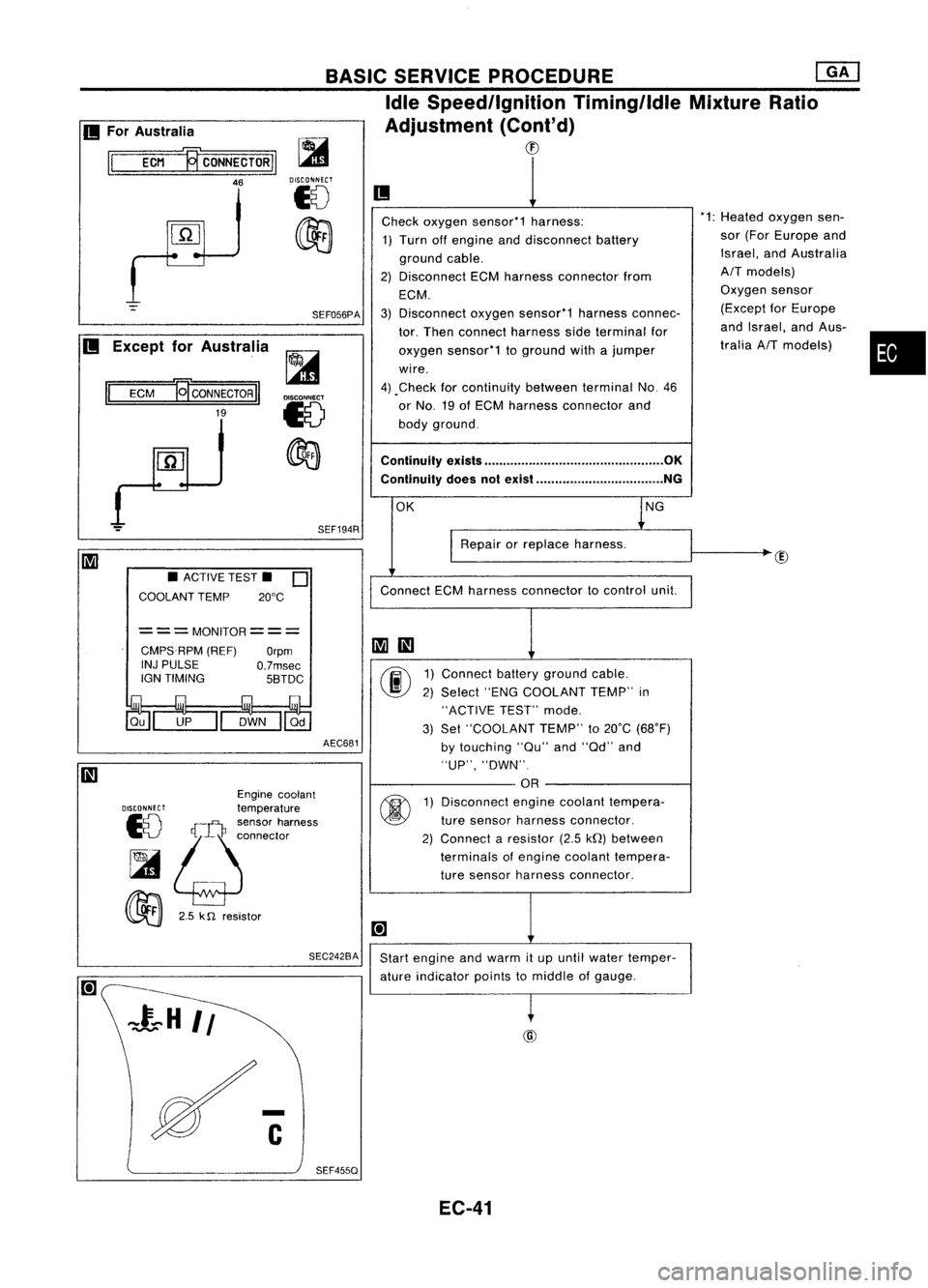
Check oxygen sensor*1 harness: *1:
Heated
1) Turn offengine anddisconnect battery sor
(For
ground cable. Israel,
a
2) Disconnect ECMharness connector from
AIT
mod
ECM. Oxygen
3) Disconnect oxygensensor*1 harnessconnec- (Except
tor. Then connect harness sideterminal for and
Isra
oxygen sensor*1 toground withajumper tralia
AI
wire.
4) .Check forcontinuity betweenterminalNo.46
or No. 19ofECM harness connector and
body ground.
Continuity exists................................................ OK
Continuity doesnotexist .................................. NG
OK lNG
I
Repair orreplace harness.
Connect ECMharness connector tocontrol unit.
~
III
00
1)
Connect batteryground cable.
2) Select "ENGCOOLANT TEMP"in
"ACTIVE TEST"mode.
3) Set "COOLANT TEMP"to20°C (68°F)
by touching "au"and"ad" and
"UP", "DWN".
OR
@
1)
Disconnect enginecoolant tempera-
ture sensor harness connector.
2) Connect aresistor (2.5kQ)between
terminals ofengine coolant tempera-
ture sensor harness connector.
[+]
Start engine andwarm itup until water temper-
ature indicator pointstomiddle ofgauge.
~
BASIC
SERVICE PROCEDURE ~
Idle Speed/Ignition Timing/IdleMixtureRatio
Adjustment (Cont'd)
CD
SEF194R
SEF056PA
~
DISCONNECT
18
~
AEC681
===MONITOR===
CMPS.RPM (REF)
Orpm
INJ PULSE
O.7msec
IGN TIMING 5BTDC
SEC242BA
•
ACTIVE TEST.
0
COOLANT TEMP 20°C
Engine coolant
DISCONNECT
temperature
10
!;j:~:~~'~";"'"
~
00
2.5k
n
resistor
II
ECM
19'
CONNECTOR
II
19
II
For Australia
II
ECM ~CONNECTORII
46
II
Except forAustralia
SEF455Q EC-41
Page 770 of 1701
ON-BOARDDIAGNOSTIC SYSTEMDESCRIPTION
CONSULT (ConI'd)
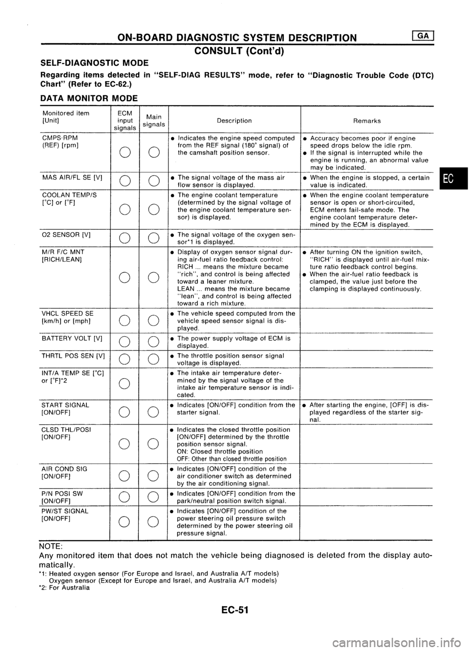
SELF-DIAGNOSTIC MODE
Regarding itemsdetected in"SELF-DIAG RESULTS"mode,referto"Diagnostic TroubleCode(DTC)
Chart" (RefertoEC-62.)
DATA MONITOR MODE
Monitored item ECM
Main
[Unit] input
signals Description
Remarks
signals
CMPS.RPM •Indicates theengine speedcomputed •Accuracy becomespoorifengine
(REF) [rpm]
00
from
theREF signal (180'signal) of
speeddropsbelow theidle rpm.
the camshaft positionsensor.
•Ifthe signal isinterrupted whilethe
engine isrunning, anabnormal value
may beindicated .
MAS AIR/FL SE[V]
0 0
•
The signal voltage ofthe mass air
•When theengine isstopped, acertain
flow sensor isdisplayed .
valueisindicated.
COOLAN TEMP/S
•The engine coolant temperature •When theengine coolant temperature
['C] or['F]
00
(determined
bythe signal voltage of
sensorisopen orshort-circuited,
the engine coolant temperature sen-ECMenters fail-safe mode.The
sor) isdisplayed.
enginecoolant temperature deter-
mined bythe ECM isdisplayed .
02 SENSOR [V]
00
•
The signal voltage ofthe oxygen sen-
sor*1 isdisplayed .
M/R F/CMNT •
Display ofoxygen sensorsignaldur-
•After turning ONthe ignition switch,
[RICH/LEAN] ingair-fuel ratiofeedback control: "RICH"isdisplayed untilair-fuel mix-
RICH ...means themixture became
tureratio feedback controlbegins.
0 0
"rich",
andcontrol isbeing affected •When theair-fuel ratiofeedback is
toward aleaner mixture.
clamped,thevalue justbefore the
LEAN ...means themixture became clampingisdisplayed continuously.
"lean", andcontrol isbeing affected
toward arich mixture .
VHCL SPEED SE
00
•
The vehicle speedcomputed fromthe
[km/h] or[mph] vehicle
speedsensor signalisdis-
played .
BATTERY VOLT[V]
0 0
•
The power supply voltage ofECM is
displayed .
THRTL POSSEN[V]
0 0
•
The throttle position sensorsignal
voltage isdisplayed.
INT/A TEMP SE['C] •The intake airtemperature deter-
or ['F]*2
0
mined
bythe signal voltage ofthe
intake airtemperature sensorisindi-
cated .
START SIGNAL
00
•
Indicates [ON/OFF] conditionfromthe•After starting theengine, [OFF]isdis-
[ON/OFF] startersignal. playedregardless ofthe starter sig-
nal.
CLSD THLIPOSI •Indicates theclosed throttle position
[ON/OFF]
00
[ON/OFF]
determined bythe throttle
position sensorsignal.
ON: Closed throttle position
OFF: Other thanclosed throttle position
AIR COND SIG
00
•
Indicates [ON/OFF] conditionofthe
[ON/OFF] air
conditioner switchasdetermined
by the airconditioning signal.
PIN POSI SW
00
•
Indicates [ON/OFF] conditionfromthe
[ON/OFF] park/neutralpositionswitchsignal.
PW/ST SIGNAL •
Indicates [ON/OFF] conditionofthe
[ON/OFF]
00
power
steering oilpressure switch
determined bythe power steering oil
pressure signal.
NOTE:
Any monitored itemthatdoes notmatch thevehicle beingdiagnosed isdeleted fromthedisplay auto-
matically.
*1: Heated oxygen sensor(ForEurope andIsrael, andAustralia A/Tmodels)
Oxygen sensor(Except forEurope andIsrael, andAustralia A/Tmodels)
*2: For Australia
EC-51
•
Page 771 of 1701
![NISSAN ALMERA N15 1995 Service Manual ON-BOARDDIAGNOSTIC SYSTEMDESCRIPTION
CONSULT (Coni'd)
Monitored item
ECM
Main
[Unit] input
signals Description
Remarks
signals
LOAD SIGNAL •Indicates [ON/OFF] conditionfromthe
[ON/OFF] reardefo NISSAN ALMERA N15 1995 Service Manual ON-BOARDDIAGNOSTIC SYSTEMDESCRIPTION
CONSULT (Coni'd)
Monitored item
ECM
Main
[Unit] input
signals Description
Remarks
signals
LOAD SIGNAL •Indicates [ON/OFF] conditionfromthe
[ON/OFF] reardefo](/manual-img/5/57349/w960_57349-770.png)
ON-BOARDDIAGNOSTIC SYSTEMDESCRIPTION
CONSULT (Coni'd)
Monitored item
ECM
Main
[Unit] input
signals Description
Remarks
signals
LOAD SIGNAL •Indicates [ON/OFF] conditionfromthe
[ON/OFF] reardefogger signaland/or lighting
switch.
0 0
ON:
Rear defogger isoperating
and/or lighting switchison.
OFF: Rear defogger isnot operating
and lighting switchisnot on.
INJ PULSE [msec]
0
•
Indicates theactual fuelinjection
•When theengine isstopped, acertain
pulse widthcompensated byECM computedvalueisindicated.
according tothe input signals.
IGN TIMING [BTDC]
0
•
Indicates theignition timingcomputed
by ECM according tothe input sig-
nals.
IACV-AACIV
[%]
•Indicates theidle aircontrol valve
0
(AAC
valve) control valuecomputed
by ECM according tothe input sig-
nals.
A/F ALPHA
[%]
•Indicates themean valueofthe air-
•When theengine isstopped, acertain
0
fuel
ratio feedback correction factor valueisindicated.
per cycle. •This data alsoincludes thedata for
the air-fuel ratiolearning control.
AIR COND RLY
0
•
Indicates theairconditioner relay
[ON/OFF] controlcondition (determined byECM
according tothe input signal).
COOLING FAN*2
•Indicates thecontrol condition ofthe
[ON/OFF] or[LOW/
coolingfans(determined byECM
HI/OFF]
0
according
tothe input signal).
ON ...Operating
LOW ...Operates atlow speed
HI ...Operates athigh speed
OFF ...Stopped
FUEL PUMP RLY
0
•
Indicates thefuel pump relaycontrol
[ON/OFF] conditiondetermined byECM accord-
ing tothe input signals.
VALVE TIMSOL*1
•The control condition ofthe valve tim-
[ON/OFF] ingsolenoid valve(determined by
ECM according tothe input signal) is
indicated.
ON ...VTC operating
OFF ...VTC notoperating
EGRC SOLIV (EVAP
•Indicates thecontrol condition ofthe
canister purgecon-
EVAPcanister purgecontrol solenoid
trol solenoid valve valveorEGR valve
&
EVAP canister
or EGR
&
EVAP can- purgecontrol solenoid valve(deter-
ister purge control
0
mined
byECM according tothe input
solenoid valve) signal).
[ON/OFF] ON'"EVAP canister purgeoperation
cut-off OFF ...EVAP canister purgeoperation
not cut-off
VOLTAGE •Voltage measured bythe voltage
[V] probe.
PULSE •Pulse width, frequency orduty cycle •Only "#"isdisplayed ifitem is
[msec] or[Hz] or measuredbythe pulse probe. unable
tobe measured .
[%]
•
Figures with"#"s aretemporary
ones. Theyarethesame figures as
an actual pieceofdata which wasjust
previously measured.
*1: GA16DE exceptforEurope andIsrael
*2: GA16DE engineA/Tmodels forEurope without heavydutykithave a2- step control [ON/OFF] system."LOW"and"HI"
are shown onCONSULT screentorepresent "ON"condition.
EC-52
Page 772 of 1701

ON-BOARDDIAGNOSTIC SYSTEMDESCRIPTION
CONSULT (Cont'd)
ACTIVE TESTMODE
TEST ITEM CONDITION JUDGEMENT
CHECKITEM(REMEDY)
• Engine: Returntothe original
•Harness andconnector
FUEL INJECTION trouble
condition If
trouble symptom disappears,
•Fuel injectors
• Change theamount offuel see
CHECK ITEM.
injection usingCONSULT . •
Oxygen sensor*1
• Engine: Afterwarming up,idle
IACV-AACIV the
engine.
Enginespeedchanges according •Harness andconnector
OPENING •
Change theIACV-AAC valve
tothe opening percent. •
IACV-AAC valve
opening percentusingCON-
SULT.
• Engine: Returntothe original
•Harness andconnector
ENG COOLANT trouble
condition
Iftrouble symptom disappears, •
Engine coolant temperature
TEMP •
Change theengine coolant
.
see CHECK ITEM. sensor
temperature indicationusing
•Fuel injectors
CONSULT.
• Engine: Returntothe original
trouble condition
Iftrouble symptom disappears,
IGNITION TIMING•
Timing light:Set •
Adjust initialignition timing
• Retard theignition timingusingsee
CHECK ITEM.
CONSULT .
• Engine: Afterwarming up,idle •
Harness andconnector
the engine. •
Compression
POWER •
A/C switch "OFF"
Enginerunsrough ordies . •
Injectors
BALANCE •
Shift lever "N" •
Power transistor
• Cut offeach injector signalone •
Spark plugs
at atime using CONSULT. •
Ignition coils
• Ignition switch:ON
COOLING FAN*3•
Turn thecooling fan"ON" and
Cooling fanmoves andstops. •
Harness andconnector
"OFF", or"LOW" and"HI" •
Cooling fanmotor
and "OFF" usingCONSULT .
• Ignition switch:ON(Engine
FUEL PUMP stopped)
Fuelpump relaymakes theoper- •Harness andconnector
• Turn thefuel pump relay"ON"
RELAY and"OFF" usingCONSULT ating
sound. •
Fuel pump relay
and listen tooperating sound.
EGRC SOLENOID
VALVE (EVAP canister
•Ignition switch:ON
purge control
•Turn solenoid valve"ON" and Solenoid
valvemakes anoperat- •
Harness andconnector
solenoid valveor
EGR valve
&
"OFF"
withtheCONSULT andingsound. •
Solenoid valve
EVAP canister listen
tooperating sound.
purge control
solenoid valve)
•Ignition switch:ON
VALVE TIMING •
Turn solenoid valve"ON" and Solenoid
valvemakes anoperat- •
Harness andconnector
SOL*2 "OFF"
usingCONSULT anding
sound. •
Solenoid valve
listen tooperating sound.
SELF-LEARNING •
Inthis test, thecoefficient ofself-learning controlmixture ratioreturns tothe original coefficient by
CONT touching
"CLEAR" onthe screen.
*1: Heated oxygen sensor(ForEurope andIsrael, andAustralia A/Tmodels)
Oxygen sensor(Except forEurope andIsrael, andAustralia A/Tmodels)
*2: GA16DE except forEurope andIsrael
*3: GA16DE engine A/Tmodels forEurope without heavydutykithave a2- step control [ON/OFF] system."LOW"and"HI"
are shown onCONSULT screentorepresent "ON"condition.
EC-53
•
Page 790 of 1701
TROUBLEDIAGNOSES -General Description
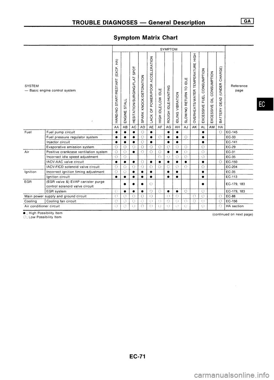
Symptom MatrixChart
SYMPTOM
:c
z
(!l
~
0
I
:c
i=
w
cL
~
<{
0::
0::
='
W
<.)
0
w
~
z
CJ
x
Cl.
-I
0
Z
0::
~
en
w
i=
0
z
<.)
0::
<{
~
0
<.)
w
w
Cl.
i=
:c
~
-I
Cl.
::?
Cl.
<.)
0::
-I
i=
<{
Q
::?
=' ::?
<{
u..
<{
0::
SYSTEM
0::
W
en
='
Reterence
~
0
CJ
0
~
z
w
en
0
w
z
0
en
0
- Basic engine control system
w
z
0
~
0::
Z
Z
page
0::
<3
~
Cl.
-I
i=
w
<.)
0
w
Q
z
z
2-
j:::
0::
0
ii
z
0
0::
~
-I
<.)
0::
='
;;:
w
:s:
='
i=
='
<{
W
-I
0
<{
-I
en
:s:
:c
~
:s:
='
6
<{
-I
Z
<.)
0
w
<{
w
en
u..
w
~
<{
00
-I
0::
en
~
Cl.
W
-I
III
0::
~
W
W
0
0
en
0
z
Q
:;
0
<{
> >
i=
~
LL
-I
>-
Z
W
0
Q
z
w
U5 U5
0::
2i
z
<{
~ :c
(!l
~:c
en en
w
<3
~
0::
~
:c
CJ
z
0::
W W
~
0::
U5
<{
<.)
CJ
='
:J
0
w
<.)
<.)
~
I
<{
Z
W
Cl.
<{
0
Q
-I
>
X
X
<{
:c
w
:c
en
-I
:c
0::
en
0
w
W
III
AA AB AC ADAEAFAG
AH AJ
AK AL
AM HA
Fuel Fuel
pump circuit
••
•
0
•
•
•
•
0
EC-145
Fuel pressure regulator system
•••
0
•
0
•
•
0
•
EC-33
Injector circuit
•• •
0
• •
• •
EC-141
Evaporative emissionsystem
00
[)
00
()
0
0 0 0
EC-29
Air Positivecrankcase ventilation system
00
•
0
0
0
••
U
()
EC-31
Incorrect idlespeed adjustment
0
0
()
(~)
C)
0 0
EC-35
IACV-AAC valvecircuit
•••
(,
••• •• •
0
EC-150
~)
IACV-FICD solenoidvalvecircuit
C)
()
()
()
0
C)
(~,
()
0
0
EC-204
Ignition Incorrectignitiontimingadjustment
0
0
•• •
•
• •
EC-35
Ignition circuit
••
•
•
• •
•
•
EC-113
EGR (EGRvalve
&)
EVAP canister purge
0
EC-179,183
control soienoid valvecircuit
••
• •
EGR system
U
••
•
r)
(,)
•
•
0
0
EC-179.
183
Main power supply andground circuit
()
() ()
0 0
()
Ci
()
0
(
~
EC-88
Cooling
I
Cooling tancircuit
()
:.'-1
U
()
(,)
',)
C)
t)
U
n
(J
0
EC-156
u
Air conditioner circuit
()
Co
u
()
CJ
UU
"
,
C:
~,
()
HAsection
•
• ;High Possibility Item
(), Low Possibility Item
EC-71
(continued
onnext page)
Page 793 of 1701
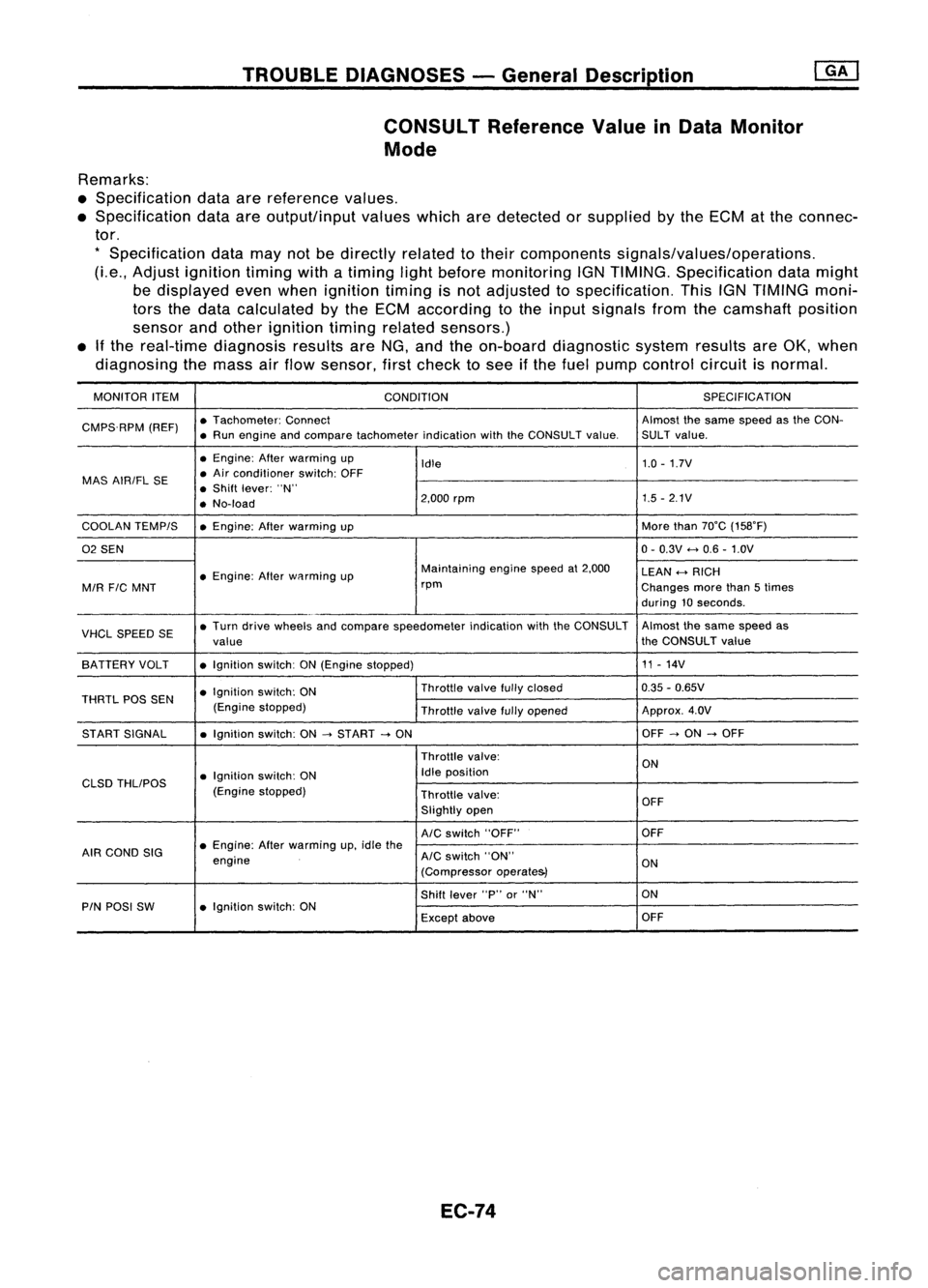
TROUBLEDIAGNOSES -General Description
CONSULT ReferenceValueinData Monitor
Mode
Remarks:
• Specification dataarereference values.
• Specification dataareoutput/input valueswhicharedetected orsupplied bythe ECM atthe connec-
tor.
*
Specification datamaynotbedirectly relatedtotheir components signals/values/operations.
(Le., Adjust ignition timingwithatiming lightbefore monitoring IGNTIMING. Specification datamight
be displayed evenwhen ignition timingisnot adjusted tospecification. ThisIGNTIMING moni-
tors thedata calculated bythe ECM according tothe input signals fromthecamshaft position
sensor andother ignition timingrelated sensors.)
• Ifthe real-time diagnosis resultsareNG, and theon-board diagnostic systemresultsareOK, when
diagnosing themass airflow sensor, firstcheck tosee ifthe fuel pump control circuitisnormal.
MONITOR ITEM
CONDITION SPEC
IFICA TION
CMPS.RPM (REF)•
Tachometer: Connect Almostthesame speed asthe CON-
• Run engine andcompare tachometer indicationwiththeCONSULT value.SULT value.
• Engine: Afterwarming up
Idle 1.0
-1.7V
MAS AIRIFL SE •
Air conditioner switch:OFF
• Shift lever: "N"
• No-load 2,000
rpm 1.5
-2.1V
COOLAN TEMPIS •Engine: Afterwarming up More
than70°C (158°F)
02 SEN 0-
0.3V
<-+
0.6 -1.0V
• Engine: Afterwflrming up Maintaining
enginespeedat2,000
LEAN
<-+
RICH
MIR
FIC
MNT rpm
Changesmorethan5times
during 10seconds .
VHCL SPEED SE•
Turn drive wheels andcompare speedometer indicationwiththeCONSULT Almost
thesame speed as
value the
CONSULT value
SA TTERY VOLT •Ignition switch:ON(Engine stopped) 11
-14V
• Ignition switch:ON Throttle
valvefullyclosed 0.35
-0.65V
THRTL POSSEN
(Enginestopped)
Throttlevalvefullyopened Approx.
4.0V
ST ART SIGNAL •Ignition switch:ON
-->
START
-->
ON OFF
-->
ON
-->
OFF
Throttle valve:
ON
• Ignition switch:ON Idle
position
CLSD THLIPOS
(Enginestopped)
Throttlevalve:
OFF
Slightly open
AIC
switch "OFF" OFF
AIR COND SIG •
Engine: Afterwarming up,idle the
engine
AIC
switch "ON"
ON
(Compressor operate&)
Shift lever "P"or"N" ON
PIN POSI SW •Ignition switch:ON
Exceptabove OFF
EC-74