1995 NISSAN ALMERA N15 Idle speed control
[x] Cancel search: Idle speed controlPage 881 of 1701
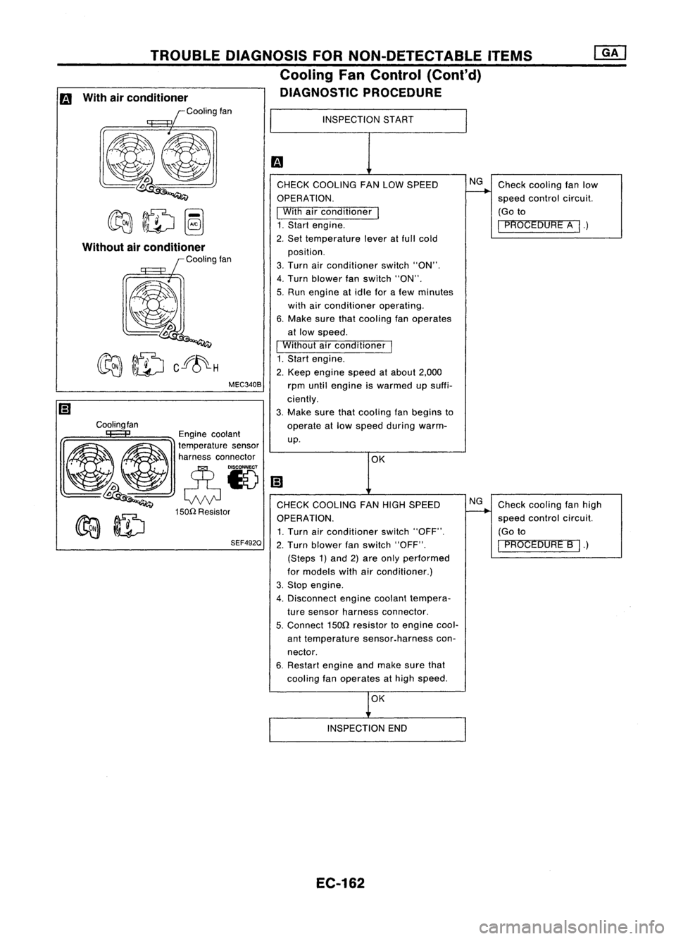
Checkcooling fanlow
speed control circuit.
(Go to
I
PROCEDURE A
I.)
Check cooling fanhigh
speed control circuit.
(Go to
I
PROCEDURE B
I.)
NG
NG
OK
INSPECTION
START
CHECK COOLING FANLOW SPEED
OPERATION.
I
With airconditioner
I
1. Start engine.
2. Set temperature leveratfull cold
position.
3. Turn airconditioner switch"ON".
4. Turn blower fanswitch "ON".
5. Run engine atidle forafew minutes
with airconditioner operating.
6. Make surethatcooling fanoperates
at low speed.
I
Without airconditioner
I
1. Start engine.
2. Keep engine speedatabout 2,000
rpm until engine iswarmed upsuffi-
ciently.
3. Make surethatcooling fanbegins to
operate atlow speed during warm-
up.
MEC340B
TROUBLE
DIAGNOSIS FORNON-DETECTABLE ITEMS
Cooling FanControl (Cant'd)
DIAGNOSTIC PROCEDURE
Cooling fan
Without
airconditioner
Coolingfan
Engine coolant
~ ~ ~a~~:;:t:a::;'~~'
~~ eN
lDoo
Q
CHECKCOOLING FANHIGH SPEED
150n
Resistor
~ ~ OPERATION.
~ ~ 1.Turn airconditioner switch"OFF".
SEF492Q
2.Turn blower fanswitch "OFF".
(Steps 1)and 2)are only performed
for models withairconditioner.)
3. Stop engine.
4. Disconnect enginecoolant tempera-
ture sensor harness connector.
5.
Connect
1500
resistor toengine cool-
ant temperature sensor.harness con-
nector.
6. Restart engineandmake surethat
cooling fanoperates athigh speed.
m
With airconditioner
Coolingfan
OK
INSPECTION END
EC-162
Page 900 of 1701
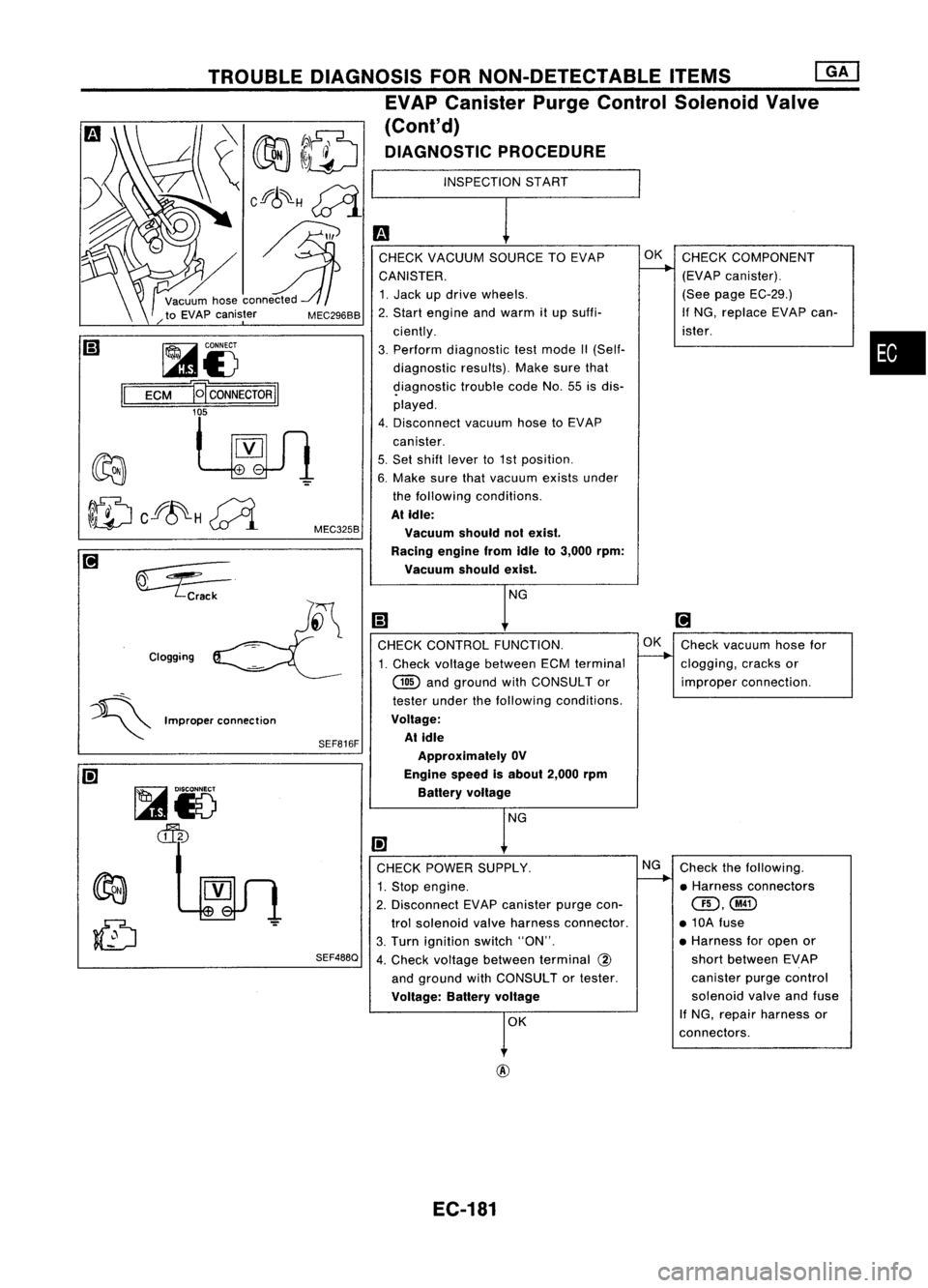
•
INSPECTION
START
m
CHECK VACUUM SOURCETOEVAP OK
CHECK COMPONENT
CANISTER.
L---.
(EVAPcanister).
1. Jack updrive wheels. (See
page EC-29.)
2. Start engine andwarm itup suffi- If
NG, replace EVAPcan-
ciently. ister.
3. Perform diagnostic testmode II(Self-
diagnostic results).Makesurethat
9iagnostic troublecodeNo.55isdis-
played.
4. Disconnect vacuumhosetoEVAP
canister.
5. Set shift lever to1st position.
6. Make surethatvacuum existsunder
the following conditions.
At Idle:
Vacuum shouldnotexist.
Racing enginefromIdleto3,000 rpm:
Vacuum shouldexist.
NG
Ii)
[!J
CHECK CONTROL FUNCTION. OK
Check vacuum hosefor
1. Check voltage between ECMterminal
--..
clogging, cracksor
@
andground withCONSULTor improperconnection.
tester underthefollowing conditions.
Voltage: At idle
Approximately OV
Engine speedisabout 2,000rpm
Battery voltage
NG
I!l
CHECK POWER SUPPLY. NG
Check thefollowing.
1. Stop engine.
I-----.
•Harness connectors
2. Disconnect EVAPcanister purgecon-
QD,@
trol solenoid valveharness connector. •10A fuse
3. Turn ignition switch"ON". •
Harness foropen or
4. Check voltage between terminal
@
short
between EVAP
and ground withCONSULTor tester. canister
purgecontrol
Voltage: Batteryvoltage
solenoid
valveandfuse
r
K If
NG, repair harness or
connectors.
SEF816F
SEF488Q
MEC325B
MEC296BB
Clogging TROUBLE
DIAGNOSIS FORNON-DETECTABLE ITEMS
[ill
EVAP Canister PurgeControl Solenoid Valve
(Cont'd)
DIAGNOSTIC PROCEDURE
~i5
ECM
B
CONNECTOR
II
'f
~VV1
~ Crack
~i5
~
=:5---
~ Improperconnection
@
EC-181
Page 905 of 1701
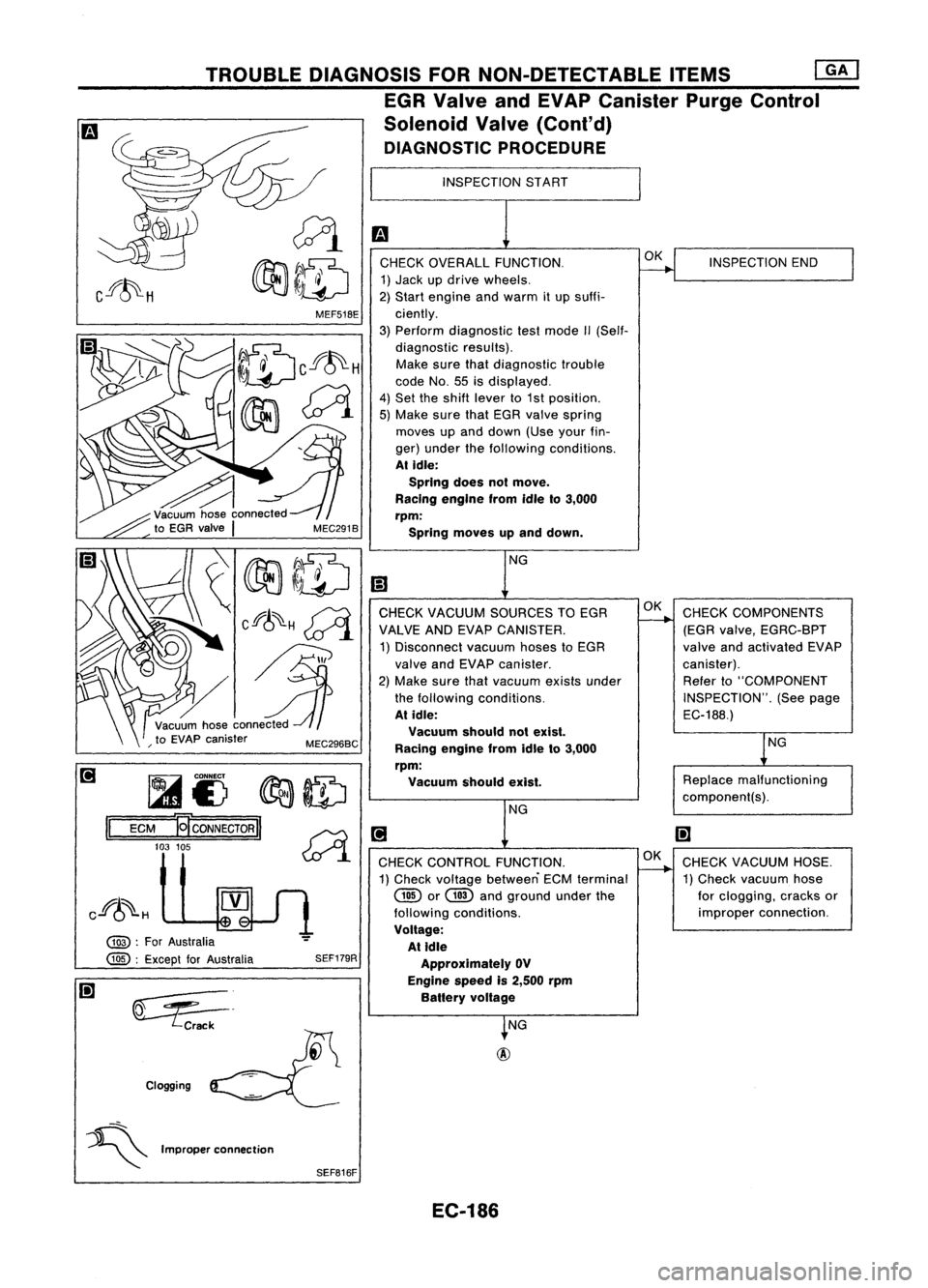
INSPECTIONSTART
m
CHECK OVERALL FUNCTION.
~INSPECTION
END
1) Jack updrive wheels.
2) Start engine andwarm itup suffi-
ciently.
3) Perform diagnostic testmode II(Self-
diagnostic results).
Make surethatdiagnostic trouble
code No.55isdisplayed.
4) Set theshift lever to1st position.
5) Make surethatEGR valve spring
moves upand down (Useyourfin-
ger) under thefollowing conditions.
At idle:
SprIng doesnotmove.
RacIng engIne fromidleto3,000
rpm:
Spring moves upand down.
NG
l!1
CHECK VACUUM SOURCES TOEGR OK
CHECK COMPONENTS
VALVE ANDEVAP CANISTER.
-----...
(EGRvalve, EGRC-BPT
1) Disconnect vacuumhosestoEGR valveandactivated EVAP
valve andEVAP canister. canister).
2) Make surethatvacuum existsunder Refer
to"COMPONENT
the following conditions. INSPECTION".(Seepage
At idle:
EC-188.)
Vacuum shouldnotexist.
lNG
Racing engine fromidleto3,000
rpm: Vacuum shouldexist.
Replace
malfunctioning
component(s).
NG
[!J
I!l
CHECK CONTROL FUNCTION. OK
CHECK VACUUM HOSE.
1) Check voltage between ECMterminal
----..
1)Check vacuum hose
@
or
GID
andground underthe forclogging, cracksor
following conditions. improper
connection.
Voltage: At Idle
Approximately OV
Engine speedis2,500 rpm
Battery voltage
~NG
SEF179R
~=.
Crack
Clogging MEF51BE
TROUBLE
DIAGNOSIS FORNON-DETECTABLE ITEMS
[]K]
EGR Valve andEVAP Canister PurgeControl
Solenoid Valve(Cont'd)
DIAGNOSTIC PROCEDURE
~I)
~ID
ECM
-gcoNNEcTORII ~
103 105
~.1
@ :
For Australia
@ :
Except forAustralia
II
Cf~H
~
~ Improperconnection
SEFB16F
EC-186
Page 917 of 1701
TROUBLEDIAGNOSIS FORNON-DETECTABLE ITEMS
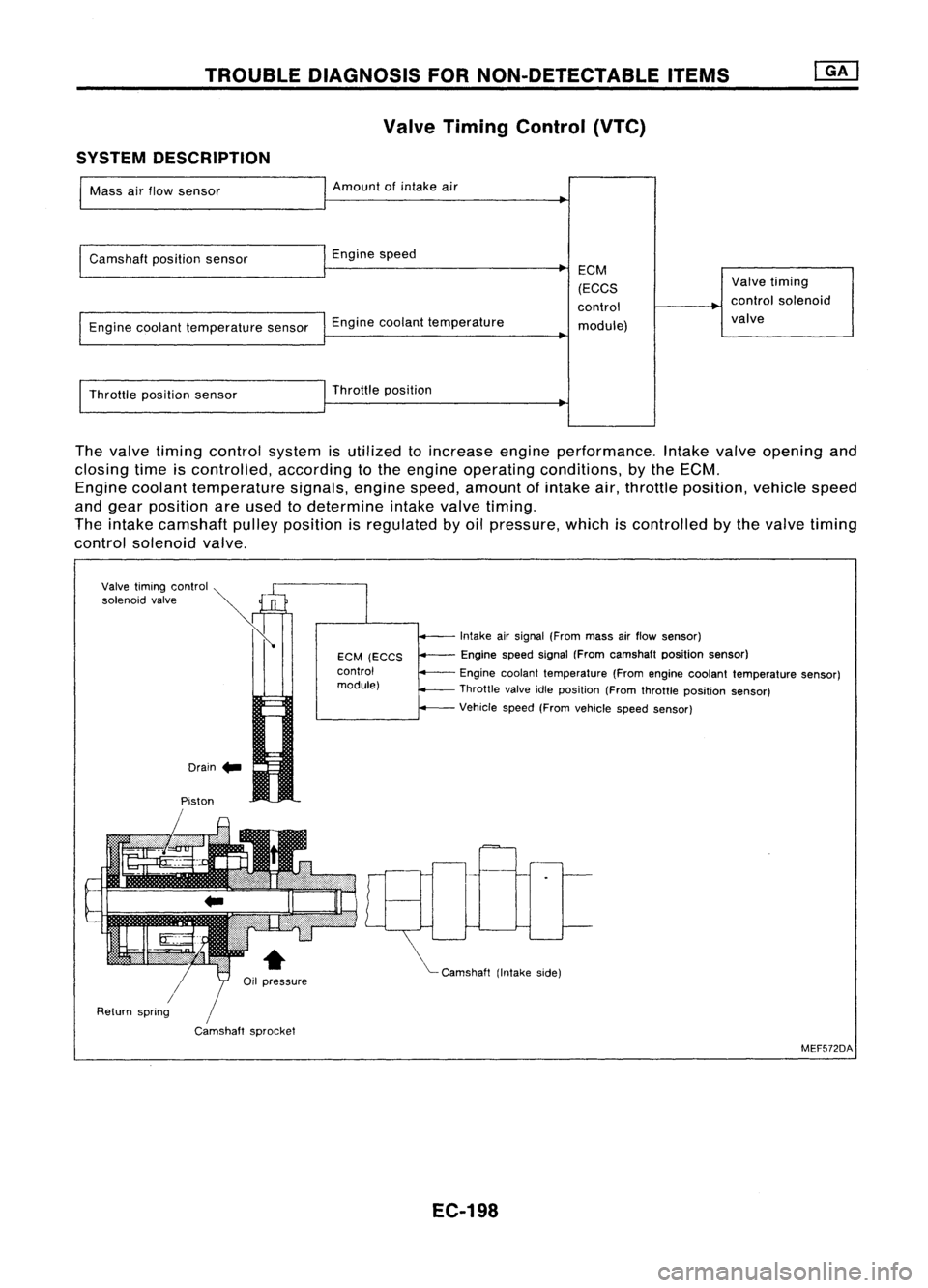
Valve Timing Control (VTC)
SYSTEM DESCRIPTION
Mass airflow sensor Amount
ofintake air
Camshaft positionsensor Enginespeed
Engine coolant temperature sensorEnginecoolant temperature ECM
(ECCS
control module) Valve
timing
control solenoid
valve
Throttle positionsensor Throttle
position
The valve timing control system isutilized toincrease engineperformance. Intakevalveopening and
closing timeiscontrolled, accordingtothe engine operating conditions, bythe ECM.
Engine coolant temperature signals,enginespeed,amount ofintake air,throttle position, vehiclespeed
and gear position areused todetermine intakevalvetiming.
The intake camshaft pulleyposition isregulated byoil pressure, whichiscontrolled bythe valve timing
control solenoid valve.
Drain .. Intake
airsignal (From massairflow sensor)
Engine speedsignal(From camshaft positionsensor)
Engine coolant temperature (Fromengine coolant temperature sensor)
Throttle valveidleposition (Fromthrottle position sensor)
Vehicle speed(Fromvehicle speedsensor)
"'- Camshaft (Intakeside)
EGM
(EGGS
control
module)
/
Camshaft sprocket
Piston
Valve
timing control ~
»
'o'""oid ,,',"
Ii
/
Return spring
MEF572DA
EC-198
Page 951 of 1701
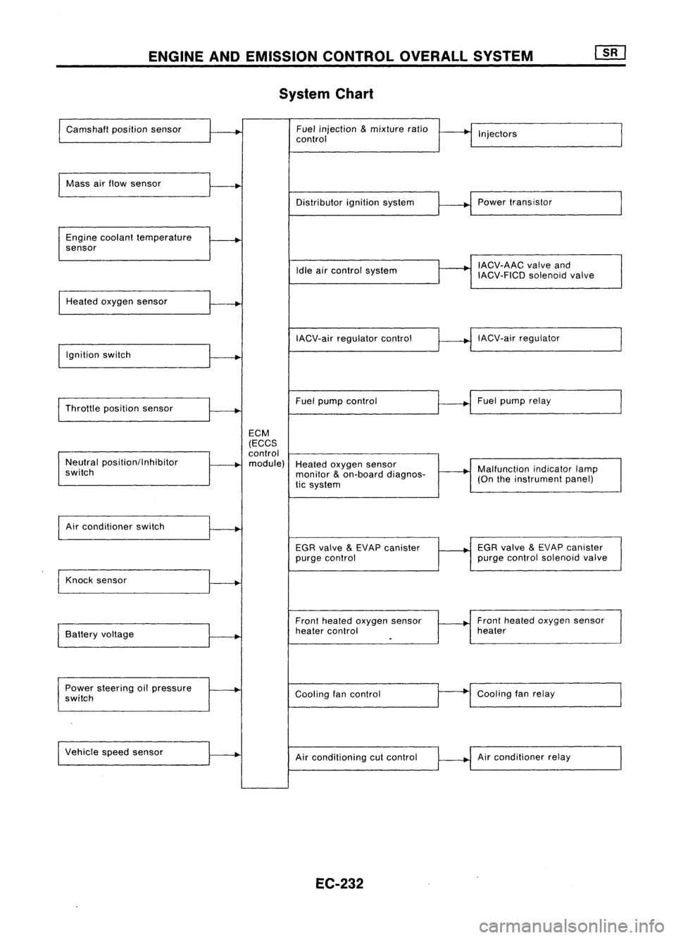
ENGINEANDEMISSION CONTROLOVERALLSYSTEM
System Chart
Camshaft positionsensor Fuel
injection
&
mixture ratio
•
I
I
control Injectors
Mass airflow sensor
I
Distributorignitionsystem
r
~1
Power transistor
Engine coolant temperature
.
sensor
I
IACV-AAC valveand
Idle aircontrol system
IACV-FICDsolenoidvalve
Heated oxygen sensor
I
IACV-airregulator control
~--..j
IACV-air regulator
I
Ignition switch
I
I
Throttle position sensor
~-+
Fuel
pump control Fuel
pump relay
ECM
(ECCS
control
Neutral position/Inhibitor
.
module) Heatedoxygen sensor
switch monitor
&
on-board diagnos-
~-+
Malfunction
indicatorlamp
tic system (On
theinstrument panel)
I
Air conditioner switch
t~
EGRvalve
&
EVAP canister
1---+
EGR
valve
&
EVAP canister
purge control purge
control solenoid valve
Knock sensor
.....
Frontheated oxygen sensor Front
heated oxygen sensor
Battery voltage
.
heater
control heater
I
.
Power steering oilpressure
~
Coolingfancontrol
--
Cooling
fanrelay
switch
Vehicle speedsensor
.....
Airconditioning cutcontrol Air
conditioner relay
EC-232
Page 952 of 1701
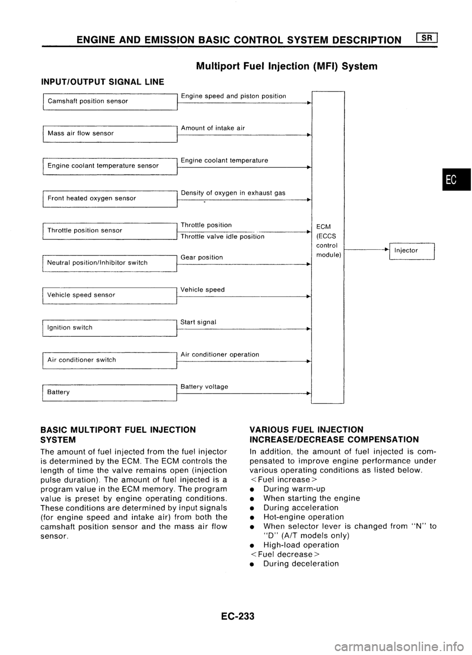
ENGINEANDEMISSION BASICCONTROL SYSTEMDESCRIPTION
Multiport FuelInjection (MFI)System
INPUT/OUTPUT SIGNALLINE
Camshaft positionsensor
Mass airflow sensor
Engine coolant temperature sensor
Front heated oxygen sensor
Throttle position sensor
Neutral position/lnhibitor switch
I
Vehicle speedsensor
Ignition switch
Air conditioner switch
Battery Engine
speedandpiston position
Amount ofintake air
Engine coolant temperature
Density ofoxygen inexhaust gas
Throttle position
Throttle valveidleposition
Gear position
I
Vehicle speed
Start signal
Air conditioner operation
Battery voltage ECM
(ECCS
control
module) Injector
•
BASIC MULTIPORT FUELINJECTION
SYSTEM
The amount offuel injected fromthefuel injector
is determined bythe ECM. TheECM controls the
length oftime thevalve remains open(injection
pulse duration). Theamount offuel injected isa
program valueinthe ECM memory. Theprogram
value ispreset byengine operating conditions.
These conditions aredetermined byinput signals
(for engine speedandintake air)from boththe
camshaft positionsensorandthemass airflow
sensor.
VARIOUS
FUELINJECTION
INCREASE/DECREASE COMPENSATION
In addition, theamount offuel injected iscom-
pensated toimprove engineperformance under
various operating conditions aslisted below.
<
Fuel increase>
• During warm-up
• When starting theengine
• During acceleration
• Hot-engine operation
• When selector leverischanged from"N"to
"0" (AfT models only)
• High-load operation
<
Fuel decrease>
• During deceleration
EC-233
Page 954 of 1701
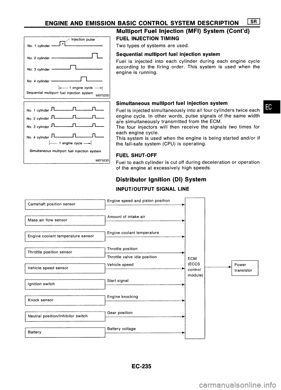
Twotypes ofsystems areused.
Sequential multiportfuelinjection system
Fuel isinjected intoeach cylinder duringeachengine cycle
according tothe firing order. Thissystem isused when the
engine isrunning.
ENGINE
ANDEMISSION BASICCONTROL SYSTEMDESCRIPTION ~
Multiport FuelInjection (MFI)System (Cont'd)
FUEL INJECTION TIMING
..--./ Injection pulse
NO.1 cylinder
---1
0/1 _
NO.3 cylinder
~n~ _
No.2
cylinder
rL
NO.4 cylinder
~n~_
~ 1engine cycle
----j
Sequential multiportfuelinjection system
MEF522D
No. 1cylinder
jl
n
rL-
No. 2cylinder
jl
n
rL-
No. 3cylinder
]l
n
rL-
NO.4 cylinder
D
n
fL-.
~- 1engine cycle
---1
Simultaneous multiportfuelinjection system
MEF523D Simultaneous
multipartfuelinjection system
Fuel isinjected simultaneously intoallfour cylinders twiceeach
engine cycle.Inother words, pulsesignals ofthe same width
are simultaneously transmittedfromtheECM.
The four injectors willthen receive thesignals twotimes for
each engine cycle.
This system isused when theengine isbeing started and/orif
the fail-safe system(CPU)isoperating.
FUEL SHUT-OFF
Fuel toeach cylinder iscut offduring deceleration oroperation
of the engine atexcessively highspeeds.
•
Distributor Ignition(DI)System
INPUT/OUTPUT SIGNALLINE
Camshaft positionsensor Engine
speedandpiston position
Mass airflow sensor Amount
ofintake air
Engine coolant temperature sensor Engine
coolant temperature
Throttle position sensor
I
Vehicle speedsensor Throttle
position
Throttle valveidleposition
I
Vehicle speed ECM
(ECCS
control module) Power
transistor
Ignition switch Start
signal
Knock sensor Engine
knocking
Neutral position/Inhibitor switchGear
position
Battery Battery
voltage
EC-235
Page 955 of 1701
A
N
600 1,000 1,4001,8002,200
Engine speed(rpm) SEF742M
Tp
(msec)
1.75
~ 1.50
.~
3l
1.25
:;
a.
c:
1.00
.Q
~ 0.75
E ENGINE
ANDEMISSION BASICCONTROL SYSTEMDESCRIPTION
Distributor Ignition(01)System (Cont'd)
SYSTEM DESCRIPTION
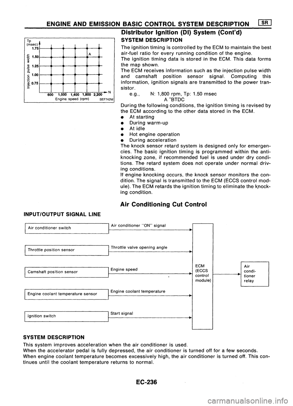
The ignition timingiscontrolled bythe ECM tomaintain thebest
air-fuel ratioforevery running condition ofthe engine.
The ignition timingdataisstored inthe ECM. Thisdataforms
the map shown.
The ECM receives information suchasthe injection pulsewidth
and camshaft positionsensorsignal.Computing this
information, ignitionsignalsaretransmitted tothe power tran-
sistor.
e.g., N:1,800 rpm,Tp:1.50 msec
AOBTDC
During thefollowing conditions, theignition timingisrevised by
the ECM according tothe other datastored inthe ECM.
• Atstarting
• During warm-up
• Atidle
• Hot engine operation
• During acceleration
The knock sensor retardsystem isdesigned onlyforemergen-
cies. Thebasic ignition timingisprogrammed withintheanti-
knocking zone,ifrecommended fuelisused under drycondi-
tions. Theretard system doesnotoperate undernormal driv-
ing conditions.
If engine knocking occurs,theknock sensor monitors thecon-
dition. Thesignal istransmitted tothe ECM (ECCS control mod-
ule). TheECM retards theignition timingtoeliminate thek.nock-
ing condition.
Air Conditioning CutControl
INPUT/OUTPUT SIGNALLINE
Air conditioner switch
Throttle position sensor
Camshaft positionsensor
Engine coolant temperature sensor
Ignition switch Air
conditioner "ON"signal
Throttle valveopening angle
Engine speed
Engine coolant temperature
Start signal
ECM
(ECCS
control module)
Air
condi-
tioner
relay
SYSTEM DESCRIPTION
This system improves acceleration whentheairconditioner isused.
When theaccelerator pedalisfully depressed, theairconditioner isturned offfor afew seconds.
When engine coolant temperature becomesexcessively high,theairconditioner isturned off.This con-
tinues untilthecoolant temperature returnstonormal.
EC-236