1995 NISSAN ALMERA N15 Idle speed control
[x] Cancel search: Idle speed controlPage 1056 of 1701
•IGN TIMING ADJ.
0
TROUBLE
DIAGNOSIS FORNON-DETECTABLE ITEMS
[ill
Idle AirControl Valve(IACV) -Auxiliary Air
Control (AAC)Valve(Cont'd)
DIAGNOSTIC PROCEDURE
-- CONDITION SETIING--
IGN/T FEEDBACK HOLD INSPECTION
START
~i5 ~i5
ECM
E[CONNECTORII
cffb
113
=
= =
MONITOR
CAS. RPM (REF)
IGN TIMING
IDLE POSITION
---
---
800rpm
15BTDC
ON
SEF786KA
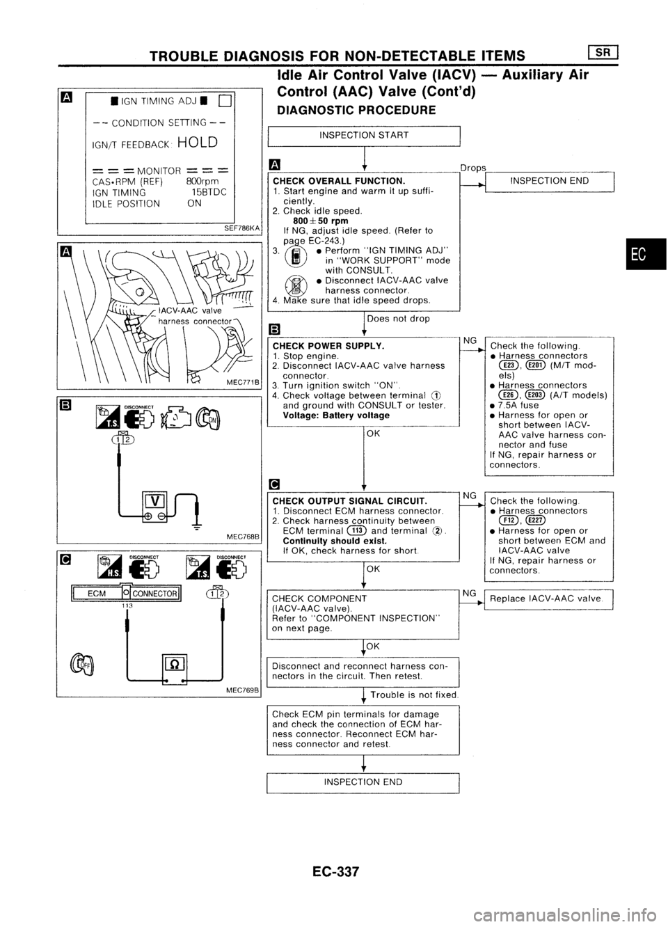
MEC768B CHECK
OVERALL FUNCTION.
1. Start engine andwarm itup suffi-
ciently.
2. Check idlespeed.
800::1:50
rpm
If NG, adjust idlespeed. (Referto
(l)
e
EC-243.)
3. .. •Perform "IGNTIMING ADJ"
I!I
in"WORK SUPPORT" mode
with CONSULT.
~ •Disconnect IACV-AACvalve
5
harness connector.
4. Ma esure thatidlespeed drops.
Does notdrop
CHECK POWER SUPPLY.
1. Stop engine.
2. Disconnect IACV-AACvalveharness
connector.
3. Turn ignition switch"ON".
4. Check voltage between terminal
G)
and ground withCONSULT ortester.
Voltage: Batteryvoltage
OK
[!1
CHECK OUTPUT SIGNALCIRCUIT.
1. Disconnect ECMharness connector.
2. Check harness continuity between
ECM terminal
CTID
andterminal
(2).
Continuity shouldexist.
If OK, check harness forshort
OK
CHECK COMPONENT
(IACV-AAC valve).
Refer to"COMPONENT INSPECTION"
on next page.
OK Drops
NG
NG
NG INSPECTION
END
Check thefollowing .
• Harness connectors
@D,
([ill)(M/Tmod-
els)
• Harness connectors
@,
@
(A/T
models)
• 7.5A fuse
• Harness foropen or
short between IACV-
AAC valve harness con-
nector andfuse
If NG, repair harness or
con nectors.
Check thefollowing.
• Harness connectors
@,@D
• Harness foropen or
short between ECMand
IACV-AAC valve
If
NG, repair harness or
connectors.
Replace IACV-AAC valve.
•
Disconnect andreconnect harnesscon-
nectors inthe circuit Thenretest
Trouble isnot fixed.
Check ECMpinterminals fordamage
and check theconnection ofECM har-
ness connector. ReconnectECMhar-
ness connector andretest
INSPECTION END
EC-337
Page 1060 of 1701
MEF023D
•
Refer to"TROUBLE
DIAGNOSES"
i!1
HA sec-
tion. INSPECTION
END
Check thefollowing.
• Harness connectors
@D,@!)
• Harness foropen or
short between IACV-
FICO solenoid valve
harness connector and
air conditioner relay
If NG, repair harness or
connectors.
OK
NG
NG
CHECK
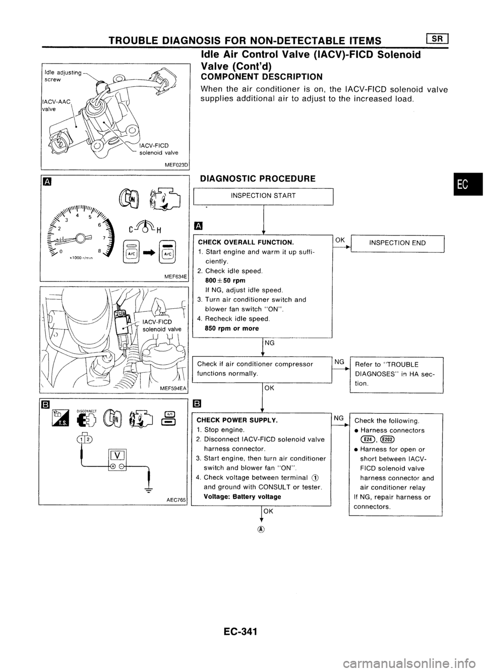
OVERALL FUNCTION.
1. Start engine andwarm itup suffi-
ciently.
2. Check idlespeed.
800:1::50
rpm
If NG, adjust idlespeed.
3. Turn airconditioner switchand
blower fanswitch "ON".
4. Recheck idlespeed.
850 rpm ormore
Check ifair conditioner compressor
functions normally.
DIAGNOSTIC
PROCEDURE
OKNG
OK
INSPECTION
START
CHECK POWER SUPPLY.
1. Stop engine.
2. Disconnect IACV-FICDsolenoidvalve
harness connector.
3. Start engine, thenturnairconditioner
switch andblower fan"ON".
4. Check voltage between terminal
CD
and ground withCONSULT ortester.
Voltage: Batteryvoltage
AEC765
MEF634E
TROUBLE
DIAGNOSIS FORNON-DETECTABLE ITEMS
[]liJ
Idle AirControl Valve(IACV)-FICD Solenoid
Valve (Cont'd)
COMPONENT DESCRIPTION
When theairconditioner ison, the IACV-FICD solenoidvalve
supplies additional airtoadjust tothe increased load.
Idle
adjusting
screw
EC-341
Page 1065 of 1701
TROUBLEDIAGNOSIS FORNON-DETECTABLE ITEMS
Cooling FanControl (Cont'd)
• COOLING FANCIRCUIT.
DOES
COOLING FAN
ROTATE ANDSTOP
EVERY 3SECONDS
7
NEXT
II
NO
II
YES
I
MEF311F
• ACTIVE TEST.
0
COOLING FAN
OFF
= ==
MONITOR
==
=
COOLAN TEMP/S
HI
With airconditioner
C
k
00lin9fan
Q
~ID~
MEF277G
M/T
models
INSPECTION START
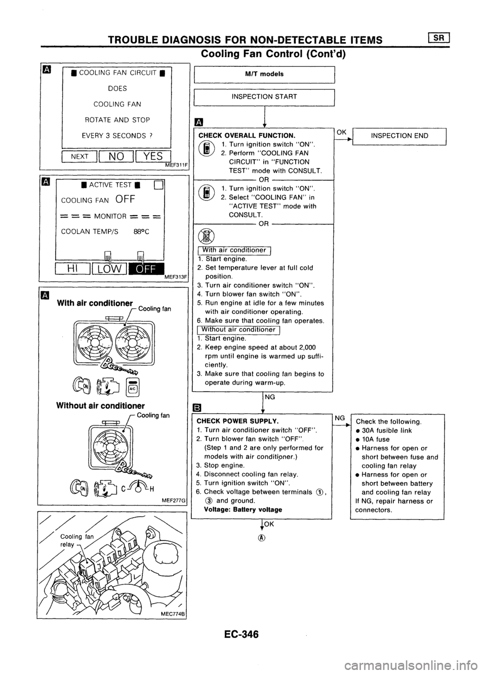
CHECK OVERALL FUNCTION.
(ij\
1.Turn ignition switch"ON".
~ 2.Perform "COOLING FAN
CIRCUIT" in"FUNCTION
TEST" modewithCONSULT.
OR
rij\
1.Turn ignition switch"ON".
\J!V
2.Select "COOLING FAN"in
"ACTIVE TEST"modewith
CONSULT.
OR
I
With airconditioner
I
1. Start engine.
2. Set temperature leveratfull cold
position.
3. Turn airconditioner switch"ON".
4. Turn blower fanswitch "ON".
5. Run engine atidle forafew minutes
with airconditioner operating.
6. Make surethatcooling fanoperates.
I
Without airconditioner
I
1. Start engine.
2. Keep engine speedatabout 2,000
rpm until engine iswarmed upsuffi-
ciently.
3. Make surethatcooling fanbegins to
operate duringwarm-up.
NG
CHECK POWER SUPPLY.
1. Turn airconditioner switch"OFF".
2. Turn blower fanswitch "OFF"
(Step 1and 2are only performed for
models withairconditi.oner.)
3. Stop engine.
4. Disconnect coolingfanrelay.
5. Turn ignition switch"ON".
6. Check voltage between terminals
G),
@
and ground.
Voltage: Batteryvoltage
OK
@
EC-346 OK
NG
INSPECTION
END
Check thefollowing.
• 30A fusible link
• 10A fuse
• Harness foropen or
short between fuseand
cooling fanrelay
• Harness foropen or
short between battery
and cooling fanrelay
If NG, repair harness or
connectors.
Page 1067 of 1701
TROUBLEDIAGNOSIS FORNON-DETECTABLE ITEMS
Cooling FanControl (Cont'd)
AlT models
INSPECTION START
Checkcooling fanlow
speed control circuit.
(Go to
I
PROCEDURE A
I,
EC-350.)
NG
2. Turn ignition switch"ON".
3. Perform "COOLING FAN
CIRCUIT" in"FUNCTION
TEST" modewithCONSULT.
OR
2. Turn ignition switch"ON".
3. Perform "COOLING FAN"in
"ACTIVE TEST"modewith
CONSULT. OR
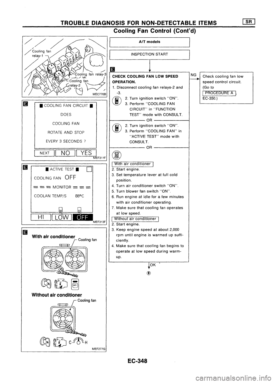
CHECK
COOLING FANLOW SPEED
OPERATION. 1. Disconnect coolingfan
re/ays-2
and
-3.
00
COOLING FAN
ROTATE ANDSTOP
EVERY 3SECONDS
I
•
COOLING FANCIRCUIT.
DOES
OK
NEXT
II
NO
II
YES
JF311F
(j)
I
With airconditioner
I
2. Start engine.
3. Set temperature leveratfull cold
position.
4. Turn airconditioner switch"ON".
5. Turn blower fanswitch "ON".
6. Run engine atidle forafew minutes
with airconditioner operating.
7. Make surethatcooling fanoperates
at low speed.
I
Without airconditioner
1
2. Start engine.
3. Keep engine speedatabout 2,000
rpm until engine iswarmed upsuffi-
ciently.
4. Make surethatcooling fanbegins to
operate atlow speed during warm-
up.
COOLAN
TEMPjS 88°C
•
ACTIVE TEST.
0
COOLING FAN
OFF
= ==
MONITOR
===
With airconditioner
lCOOtingfan
@l
~ID~
==H=I
=11L~W I
EC-348
Page 1136 of 1701
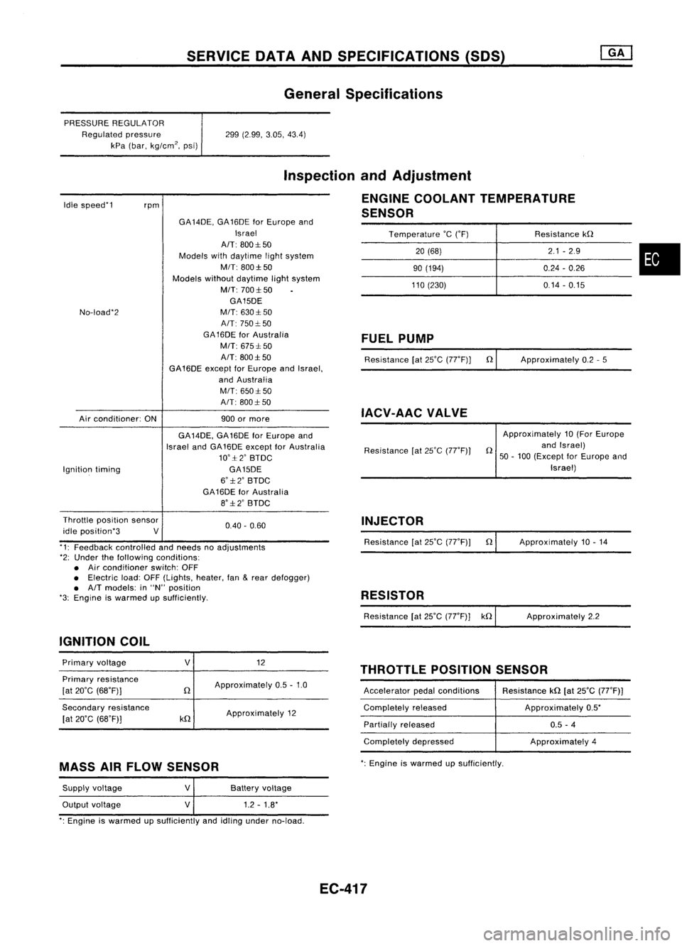
SERVICEDATAANDSPECIFICATIONS (SOS)
General Specifications
PRESSURE REGULATOR
Regulated pressure
kPa (bar, kg/cm
2,
psi) 299
(2.99, 3.05,43.4)
Idle speed'1
rpm
Inspection
andAdjustment
ENGINE COOLANT TEMPERATURE
SENSOR
Temperature
'c
('F) Resistancekn
20 (68) 2.1
-2.9
•
90
(194) 0.24-0.26
110 (230) 0.14-0.15
No-load'2
Air conditioner: ONGA
14DE, GA16DE forEurope and
Israel
AIT: 800:1:50
Models withdaytime lightsystem
MIT: 800:1:50
Models withoutdaytime lightsystem
M/T: 700:1:50
GA15DE
M/T: 630:1: 50
A/T: 750:1: 50
GA 16DE forAustralia
M/T: 675:1: 50
A/T: 800:1:50
GA16DE exceptforEurope andIsrael,
and Australia
M/T: 650:1:50
A/T: 800:1: 50
900 ormore
FUEL
PUMP
Resistance [at25'C (77'F)] n
IACV-AAC VALVE
Approximately
0.2-5
Ignition timing GA
14DE, GA16DE forEurope and
Israel andGA16DE except forAustralia
10':1:2' BTDC
GA15DE
6':1:2' BTDC
GA16DE forAustralia
8':1:2' BTDC Resistance
[at25'C (77'F)) Approximately
10(For Europe
n andIsrael)
50 -100 (Except forEurope and
Israel)
0.40. 0.60
Throttle
position sensor
idle position'3 V
'1: Feedback controlled andneeds noadjustments
'2: Under thefollowing conditions:
• Air conditioner switch:OFF
• Electric load:OFF(Lights, heater,fan
&
rear defogger)
• A/T models: in"N" position
'3: Engine iswarmed upSUfficiently.
IGNITION COIL INJECTOR
Resistance [at25'C (77'F)) n
RESISTOR
Resistance [at25'C (77'F)] kn Approximately
10.14
Approximately 2.2
THROTTLE POSITIONSENSOR
Primary
voltage
Primary resistance
[at 20'C (68'F)]
Secondary resistance
[at 20'C (68'F)]
V
n
kn
12
Approximately 0.5-1.0
Approximately 12 Accelerator
pedalconditions
Completely released
Partially released
Completely depressed Resistance
kn[at25'C (77'F))
Approximately 0.5'
0.5 -4
Approximately 4
MASS AIRFLOW SENSOR
':
Engine iswarmed upsufficiently.
Supply voltage
Output voltage
V
V
Battery
voltage
1.2 -1.8'
': Engine iswarmed upSUfficiently andidling under no-load.
EC-417
Page 1137 of 1701
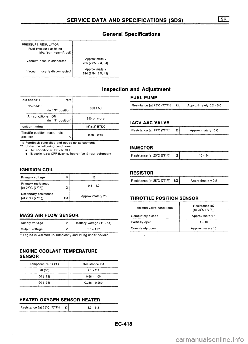
SERVICEDATAANDSPECIFICATIONS (SOS)
General Specifications
PRESSURE REGULATOR
Fuel pressure atidling
kPa (bar, kg/cm
2,
psi)
Vacuum hoseisconnected
Vacuum hoseisdisconnected Approximately
235 (2.35. 2.4.34)
Approxi mately
294 (2.94, 3.0,43)
Idle speed'1
No-load'2 rpm
(in "N" position) 800:1:50
Inspection
andAdjustment
FUEL PUMP
Resistance [at25'C (77'F)] n
Approximately 0.2-5.0
Air conditioner: ON
(in "N" position)
Ignition timing
Throttle position sensoridle
position V850
ormore
IACV-AACVALVE
15':1:2' BTDC
Resistance[at25'C (77'F)] n
0.35 -0.65 Approximately
10.0
'1: Feedback controlled andneeds noadjustments
'2: Under thefollowing conditions:
• Air conditioner switch:OFF
• Electric load:OFF(Lights, heaterfan
&
rear defogger)
IGNITION COIL INJECTOR
Resistance [at25'C (77'F)) n'
1_0_-_1_4 _
RESISTOR
Primary voltage
Primary resistance
[at 25'C (77'F))
V
12
0.5 -1.0 Resistance
[at25'C (77'F)) kn ApproXimately 2.2
Secondary resistance
[at 25'C (77'F))
kn
Approximately
25
THROTTLEPOSITIONSENSOR
MASS AIRFLOW SENSOR
Supply voltage
Output voltage
V
V
Battery
voltage (11-14)
1.3 -1.7'
Throttle
valveconditions
Completely closed
Partially open
Completely open Resistance
kn
[at 25'C (77'F)]
Approximately 1
1 - 10
Approximately 10
': Engine iswarmed upsufficiently andidling under no-load.
ENGINE COOLANT TEMPERATURE
SENSOR
Temperature
'c
('F)
20 (68)
50 (122)
90 (194) Resistance
kn
2.1-2.9
0.68 -1.00
0.236 -0.260
HEATED OXYGEN SENSOR HEATER
Resistance [at25'C (77'F)] n
I
3.3-6.3
EC-418
Page 1399 of 1701
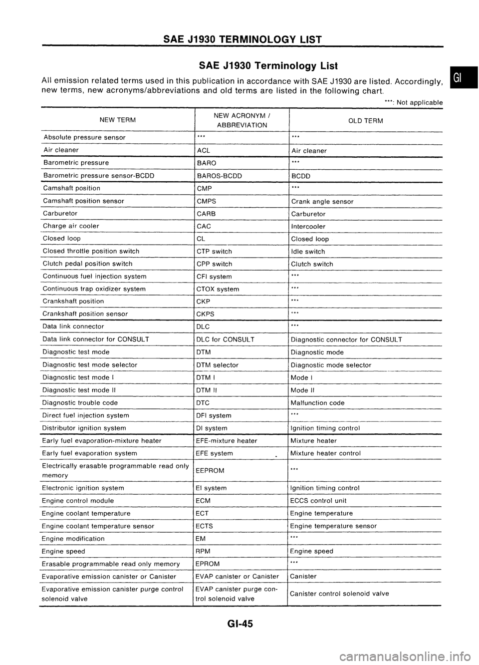
SAEJ1930 TERMINOLOGY LIST
SAE J1930 Terminology List
All emission relatedtermsusedinthis publication inaccordance withSAE J1930 arelisted. Accordingly,
new terms, newacronyms/abbreviations andoldterms arelisted inthe following chart.
"':Not applicable
NEW TERM NEW
ACRONYM /
ABBREVIATION OLD
TERM
Absolute pressure sensor
'" '"
Air cleaner
ACLAircleaner
Barometric pressure
BARO
."
Barometric pressuresensor-BCDD
BAROS-BCDD BCDD
Camshaft position
CMP
'"
Camshaft positionsensor
CMPS Crankanglesensor
Carburetor CARBCarburetor
Charge aircooler
CACIntercooler
Closed loop
CLClosedloop
Closed throttle position switch
CTPswitch
Idleswitch
Clutch pedalposition switch
CPPswitch Clutchswitch
Continuous fuelinjection system
CFIsystem
'"
Continuous trapoxidizer system
CTOXsystem
...
Crankshaft position
CKP
'"
Crankshaft positionsensor
CKPS
~.**
Data linkconnector
DLC
,
..
Data linkconnector forCONSULT
DLCforCONSULT DiagnosticconnectorforCONSULT
Diagnostic testmode
DTMDiagnosticmode
Diagnostic testmode selector
DTMselector Diagnosticmodeselector
Diagnostic testmode I
DTMI ModeI
Diagnostic testmode II
DTMII ModeII
Diagnostic troublecode
DTC Malfunctioncode
Direct fuelinjection system
DFIsystem
..
,
Distributor ignitionsystem DIsystem Ignitiontimingcontrol
Early fuelevaporation-mixture heater
EFE-mixtureheater Mixture
heater
Early fuelevaporation system
EFEsystem
.
Mixture
heatercontrol
Electrically erasableprogrammable readonly
EEPROM
'"
memory
Electronic ignitionsystem EIsystem Ignitiontimingcontrol
Engine control module ECMECCScontrol unit
Engine coolant temperature ECTEngine
temperature
Engine coolant temperature sensor ECTS Engine
temperature sensor
Engine modification EM
'"
Engine speed RPM
Enginespeed
Erasable programmable readonlymemory EPROM
'"
Evaporative emissioncanisterorCanister EVAP
canister orCanister Canister
Evaporative emissioncanisterpurgecontrol EVAP
canister purgecon-
Canister controlsolenoid valve
solenoid valve trol
solenoid valve
GI-45
•
Page 1400 of 1701
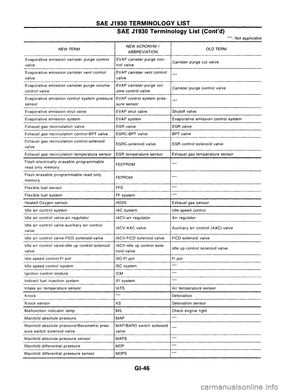
SAEJ1930 TERMINOLOGY LIST
SAE J1930 Terminology List(Cont'd)
***:
Not applicable
NEW TERM NEW
ACRONYM /
OLDTERM
ABBREVIATION
Evaporative emissioncanisterpurgecontrol EVAPcanister purgecon-
Canister purgecutvalve
valve trol
valve
Evaporative emissioncanisterventcontrol EVAPcanister ventcontrol
***
valve valve
Evaporative emissioncanisterpurgevolume EVAPcanister purgevol-
Canister purgecontrol valve
control valve ume
control valve
Evaporative emissioncontrolsystem pressure EVAP
control system pres-
***
sensor suresensor
Evaporative emissionshutvalve EVAP
shutvalve Shutoffvalve
Evaporative emissionsystem EVAPsystem Evaporative
emissioncontrolsystem
Exhaust gasrecirculation valve EGR
valve EGRvalve
Exhaust gasrecirculation control-BPTvalveEGRC-BPT valve BPT
valve
Exhaust gasrecirculation control-solenoid
EGRC-solenoidvalveEGR
control solenoid valve
valve
Exhaust gasrecirculation temperaturesensorEGRtemperature sensorExhaustgastemperature sensor
Flash electrically erasableprogrammable
FEEPROM
***
read onlymemory
Flash erasable programmable readonly
FEPROM
**.
memory
Flexible fuelsensor FFS
***
Flexible fuelsystem
FFsystem
***
Heated Oxygen sensor H02SExhaustgassensor
Idle aircontrol system lACsystem Idlespeed control
Idle aircontrol valve-air regulator IACV-airregulator Airregulator
Idle aircontrol valve-auxiliary aircontrol
IACV-AACvalve Auxiliaryaircontrol (AAC)valve
valve
Idle aircontrol valve-FICO solenoidvalve
IACV-FICDsolenoidvalve FICOsolenoid valve
Idle aircontrol valve-idle upcontrol solenoid IACV-idleupcontrol sole-
Idleupcontrol solenoid valve
valve noidvalve
Idle speed control-FI pot ISC-FIpot FIpot
Idle speed control system ISCsystem
***
Ignition controlmodule ICM
***
Indirect fuelinjection system IFIsystem
***
Intake airtemperature sensor IATS Airtemperature sensor
Knock
***
Detonation
Knock sensor
KSDetonation
sensor
Malfunction indicatorlamp MIL
Checkengine light
Manifold absolutepressure MAP
***
Manifold absolutepressure/Barometric pres-MAP/BARO switchsolenoid
***
sure switch solenoid valve valve
Manifold absolutepressure sensor MAPS
**.
Manifold differential pressure MOP
***
Manifold differential pressuresensor MOPS
***
GI-46