1995 NISSAN ALMERA N15 wheel
[x] Cancel search: wheelPage 1668 of 1701
PRECAUTIONSANDPREPARATION
Precautions
SUPPLEMENTAL RESTRAINTSYSTEM(SRS)"AIRBAG"
(Dual AirBag System)
The Supplemental RestraintSystem"AirBag" usedalong withaseat belt,helps toreduce therisk or
severity ofinjury tothe driver andfront passenger inafrontal collision. TheSupplemental Restraint
System consists ofair bag modules (locatedinthe center ofthe steering wheelandonthe instrument
panel onthe passenger side),adiagnosis sensorunit,warning lamp,wiring harness andspiral cable.
Information necessarytoservice thesystem safelyisincluded inthe
RSsection
ofthis Service Manual.
WARNING: • Toavoid rendering theSRS inoperative, whichcouldincrease therisk ofpersonal injuryordeath
in the event ofacollision whichwould resultinair bag inflation, allmaintenance mustbeperformed
by an authorized NISSANdealer.
• Improper maintenance, includingincorrectremovalandinstallation ofthe SRS, canlead topersonal
injury caused byunintentional activationofthe system.
• Donot use electrical testequipment onany circuit related tothe SRS unless instructed tointhis
Service Manual. SRSwiring harnesses arecovered withyellow insulation eitherjustbefore the
harness connectors orfor the complete harness,foreasy identification.
SUPPLEMENTAL RESTRAINTSYSTEM(SRS)"AIRBAG"
(Single AirBag System)
The Supplemental RestraintSystem"AirBag" andused along withaseat belt,helps toreduce therisk
or severity ofinjury tothe driver inafrontal collision. TheSupplemental RestraintSystemconsists of
an air bag module (located inthe center ofthe steering wheel),adiagnosis sensorunit,warning lamp,
wiring harness andspiral cable. Information necessarytoservice thesystem safelyisincluded inthe
RS section
ofthis Service Manual.
WARNING: • Toavoid rendering theSRS inoperative, whichcouldincrease therisk ofpersonal injuryordeath
in the event ofacollision whichwould resultinair bag inflation, allmaintenance mustbeperformed
by an authorized NISSANdealer.
• Improper maintenance, includingincorrectremovalandinstallation ofthe SRS, canlead topersonal
injury caused byunintentional activationofthe system.
• Donot use electrical testequipment onany circuit related tothe SRS unless instructed tointhis
Service Manual.
STEERINGSYSTEM
• Before disassembly, thoroughlycleantheoutside ofthe unit.
• Disassembly shouldbedone inaclean workarea. Itis important toprevent theinternal partsfrom
becoming contaminated bydirt orother foreign matter.
• Place disassembled partsinorder, onaparts rack,fore"asier andproper assembly.
• Use nylon cloths orpaper towels toclean theparts; common shopragscanleave lintthat might
interfere withtheir operation.
• Before inspection orreassembly, carefullycleanallparts withageneral purpose, non-flammable
solvent.
• Before assembly, applyacoat ofrecommended ATF*tohydraulic parts.Vaseline maybeapplied to
O-rings andseals. Donot use any grease.
• Replace allgaskets, sealsandO-rings. Avoiddamaging O-rings,sealsandgaskets duringinstalla-
tion. Perform functional testswhenever designated.
*:
Automatic transmission fluid
ST-2
Page 1669 of 1701
Toolnumber
Tool name PRECAUTIONS
ANDPREPARATION
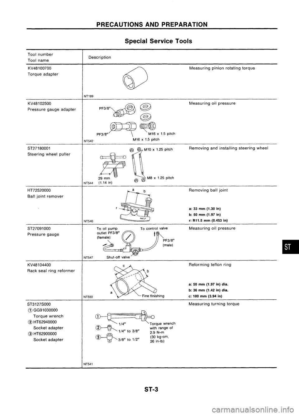
Special Service Tools
Description
KV481 00700
Torque adapter
KV481 02500
Pressure gaugeadapter NT169
NT542 PF3/B"~
@
@
PF3/B"~ ~x1.5 pitch
M16 x1.5 pitch Measuring
pinionrotating torque
Measuring oilpressure
ST27180001
Steering wheelpuller
NT544(1.14
in)
@Q'O
,'25 0;'0'
@ @
MB
x1.25 pitch Removing
andinstalling steeringwheel
HT72520000
Ball joint remover
ST27091000 Pressure gauge
KV481 04400
Rack sealringreformer
ST3127S000
G)
GG91030000
Torque wrench
@ HT62940000
Socket adapter
@
HT62900000
Socket adapter NT546
NT547
NT550
NT541 To
control valve
Shut-off valve
~ 1/4"~rque wrench
~ withrange of
1/4"
to
3/B" 2.9
N.m
~ ""(30kg-em,
'V
'td"
3/B
to
1/2
26
in-Ib)
ST-3 Removing
balljoint
a:
33
mm
(1.30
in)
b: 50
mm
(1.97
in)
r:
R11.5
mm
(0.453
in)
Measuring oilpressure
Reforming teflonring
a: 50 mm (1.97 in)dia.
b: 36 mm (1.42 in)dia.
c:
100
mm
(3.94
in)
Measuring turningtorque
•
Page 1671 of 1701
ON-VEHICLESERVICE
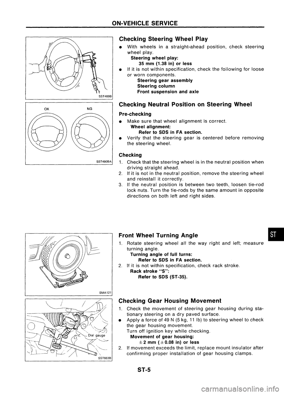
Checking SteeringWheelPlay
• With wheels inastraight-ahead position,checksteering
wheel play.
Steering wheelplay:
35 mm (1.38 in)orless
• Ifit is not within specification, checkthefollowing forloose
or worn components.
Steering gearassembly
Steering column
Front suspension andaxle
SST489B
OK
NGChecking
NeutralPosition onSteering Wheel
Pre-checking
• Make surethatwheel alignment iscorrect.
Wheel alignment:
Refer toSOS inFA section.
• Verify thatthesteering geariscentered beforeremoving
the steering wheel.
Checking
SST490BA
1.Check thatthesteering wheelisin the neutral position when
driving straight ahead.
2. Ifit is not inthe neutral position, removethesteering wheel
and reinstall itcorrectly.
3. Ifthe neutral position isbetween twoteeth,. loosen tie-rod
lock nuts. Turnthetie-rods bythe same amount inopposite
directions onboth leftand right sides.
Front Wheel Turning Angle •
1. Rotate steering wheelallthe way right andleft;measure
turning angle.
Turning angleoffull turns:
Refer toSOS inFA section.
2. Ifit is not within specification, checkrackstroke.
Rack stroke
"S":
Refer toSOS (ST-35).
SMA127 Checking GearHousing Movement
1. Check themovement ofsteering gearhousing duringsta-
tionary steering onadry paved surface.
• Apply aforce of49 N(5 kg, 11Ib) tosteering wheeltocheck
the gear housing movement.
Turn offignition keywhile checking.
Movement ofgear housing:
:I:
2 mm
(:I:
0.08 in)orless
2. Ifmovement exceedsthelimit, replace mountinsulator after
confirming properinstallation ofgear housing clamps.
ST-5
Page 1672 of 1701
ON-VEHICLESERVICE
Checking andAdjusting DriveBelts(Forpower
steering)
Refer to"Checking DriveBelts" for"ENGINE MAINTENANCE"
in MA section.
SST476C
S
r
SST681B Checking
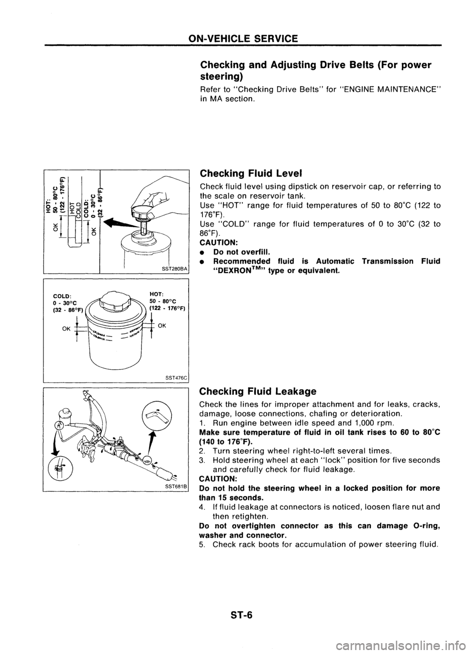
Fluidlevel
Check fluidlevel using dipstick onreservoir cap,orreferring to
the scale onreservoir tank.
Use "HOT" rangeforfluid temperatures of50 to80°C (122to
176°F).
Use "COLD" rangeforfluid temperatures of0to 30°C (32to
86°F).
CAUTION:
• Donot overfill.
• Recommended fluidisAutomatic Transmission Fluid
''DEXRON™,, typeorequivalent.
Checking Fluidleakage
Check thelines forimproper attachment andforleaks, cracks,
damage, looseconnections, chafingordeterioration.
1. Run engine between idlespeed and1,000 rpm.
Make suretemperature offluid inoil tank rises to60 to80°C
(140 to176°F).
2. Turn steering wheelright-to-Ieft severaltimes.
3. Hold steering wheelateach "lock" position forfive seconds
and carefully checkforfluid leakage.
CAUTION:
Do not hold thesteering wheelinalocked position formore
than 15seconds.
4. Iffluid leakage atconnectors isnoticed, loosenflarenutand
then retighten.
Do not overtighten connectorasthis candamage O-ring,
washer andconnector.
5. Check rackboots foraccumulation ofpower steering fluid.
ST-6
Page 1673 of 1701
SST491B
SST090B ON-VEHICLE
SERVICE
Bleeding Hydraulic System
1. Raise frontendofvehicle untilwheels areclear ofthe
ground.
2. Add fluid intooiltank tospecified level.Thenquickly turn
steering wheelfullytoright andleftand lightly touchsteer-
ing stoppers.
Repeat steering wheeloperation untilfluid level nolonger
decreases.
3. Start engine.
Repeat step2.above.
• Incomplete airbleeding willcause thefollowing tooccur.
When thishappens, bleedairagain.
a. Air bubbles inreservoir tank
b. Clicking noiseinoil pump
c. Excessive buzzinginoil pump
Fluid noise mayoccur inthe valve oroil pump. Thisiscommon
when thevehicle isstationary orwhile turning thesteering
wheel slowly. Thisdoes notaffect theperformance ordurabil-
ity ofthe system.
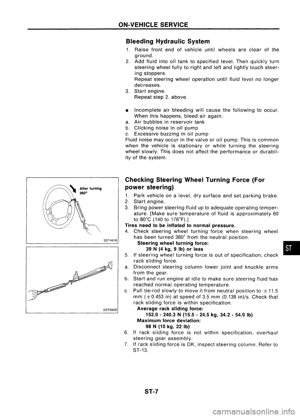
Checking SteeringWheelTurning Force(For
power steering)
1. Park vehicle onalevel, drysurface andsetparking brake.
2. Start engine.
3. Bring power steering fluiduptoadequate operating temper-
ature. [Make suretemperature offluid isapproximately 60
to 80°C (140to176°F).]
Tires needtobe inflated tonormal pressure.
4. Check steering wheelturning forcewhen steering wheel
has been turned 360°from theneutral position.
Steering wheelturning force: •
39 N(4 kg, 9Ib) orless
5.
If
steering wheelturning forceisout ofspecification, check
rack sliding force.
a. Disconnect steeringcolumnlowerjointandknuckle arms
from thegear.
b. Start andrunengine atidle tomake suresteering fluidhas
reached normaloperating temperature.
c. Pull tie-rod slowlytomove itfrom neutral position to
::l::
11.5
mm
(::l::
0.453 in)atspeed of3.5 mm (0.138 in)/s.Check that
rack sliding forceiswithin specification.
Average racksliding force:
152.0 -240.3 N(15.5 -24.5 kg,34.2 -54.0 Ib)
Maximum forcedeviation:
98 N(10 kg, 22Ib)
6.
If
rack sliding forceisnot within specification, overhaul
steering gearassembly.
7. Ifrack sliding forceisOK, inspect steering column.Referto
ST-13.
ST-7
Page 1674 of 1701
ST27091000
.. :Direction ofoil flow Low-pressure
hose SST834-AON-VEHICLE
SERVICE
Checking Hydraulic System
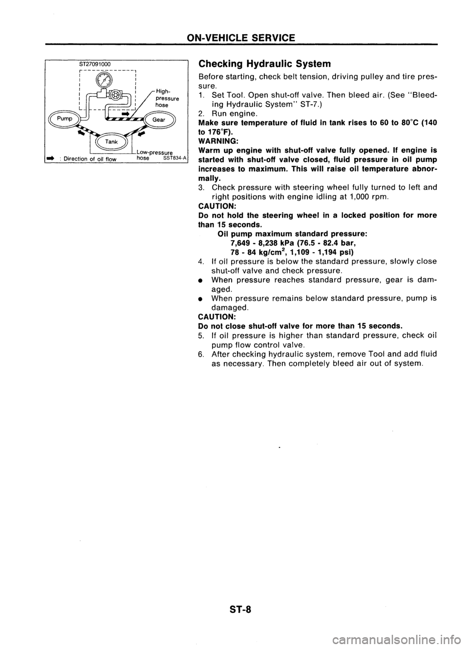
Before starting, checkbelttension, drivingpulleyandtirepres-
sure. 1. Set Tool. Open shut-off valve.Thenbleed air.(See "Bleed-
ing Hydraulic System"ST-7.)
2. Run engine.
Make suretemperature offluid intank rises to60 to80°C (140
to 176°F).
WARNING:
Warm upengine withshut-off valvefullyopened. Ifengine is
started withshut-off valveclosed, fluidpressure inoil pump
increases tomaximum. Thiswillraise oiltemperature abnor-
mally.
3. Check pressure withsteering wheelfullyturned toleft and
right positions withengine idlingat1,000 rpm.
CAUTION:
Do not hold thesteering wheelinalocked position formore
than 15seconds.
Oil pump maximum standardpressure:
7,649 -8,238 kPa(76.5 .82.4 bar,
78 -84 kg/cm
2,
1,109-1,194 psi)
4.
If
oil pressure isbelow thestandard pressure, slowlyclose
shut-off valveandcheck pressure.
• When pressure reachesstandard pressure, gearisdam-
aged.
• When pressure remainsbelowstandard pressure, pumpis
damaged.
CAUTION: Do not close shut-off valveformore than15seconds.
5.
If
oil pressure ishigher thanstandard pressure, checkoil
pump flowcontrol valve.
6. After checking hydraulic system,removeToolandaddfluid
as necessary. Thencompletely bleedairout ofsystem.
S1-8
Page 1675 of 1701
![NISSAN ALMERA N15 1995 Service Manual STEERINGWHEELANDSTEERING COLUMN
Removal andInstallation
SEC. 484.487.488
_~ ~4.0-4.9 (0.4 -0.5, 35-43)
ij] :
N.m (kg-m, in-Ib)
co;J :
N.m (kg-m. ft-Ib) With
airbag
Withoutairbag
SST538C
G)
Airb NISSAN ALMERA N15 1995 Service Manual STEERINGWHEELANDSTEERING COLUMN
Removal andInstallation
SEC. 484.487.488
_~ ~4.0-4.9 (0.4 -0.5, 35-43)
ij] :
N.m (kg-m, in-Ib)
co;J :
N.m (kg-m. ft-Ib) With
airbag
Withoutairbag
SST538C
G)
Airb](/manual-img/5/57349/w960_57349-1674.png)
STEERINGWHEELANDSTEERING COLUMN
Removal andInstallation
SEC. 484.487.488
_~ ~4.0-4.9 (0.4 -0.5, 35-43)
ij] :
N.m (kg-m, in-Ib)
co;J :
N.m (kg-m. ft-Ib) With
airbag
Withoutairbag
SST538C
G)
Airbag module
@
Horn pad
@
Steering wheel
@
Spiral cable
@
Column cover
@
Combination switch
(J)
Steering columnassembly
@
Lower joint
@
Boot
CAUTION (SRSmodels only): •
• The rotation ofthe spiral cable(SRS"Airbag" component
part) islimited. Ifthe steering gearmust beremoved, set
the front wheels inthe straight-ahead direction.Donot
rotate thesteering columnwhilethesteering gearis
removed.
• Remove thesteering wheelbefore removing thesteering
lower jointtoavoid damaging theSRS spiral cable.
STEERING WHEEL
With AirBag
• Remove airbag module andspiral cable.
Refer to"Removal -Air Bag Module andSpiral Cable",
"SUPPLEMENTAL RESTRAINTSYSTEM"inRS section.
SBF812E ST-9
Page 1676 of 1701
STEERINGWHEELANDSTEERING COLUMN
Removal andInstallation (Cont'd)
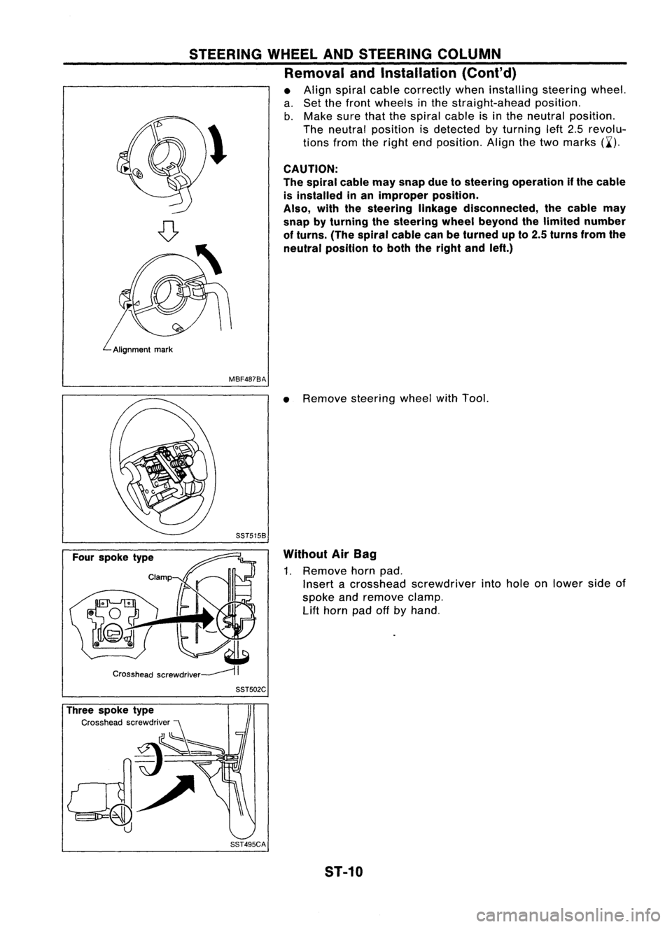
• Align spiral cablecorrectly wheninstalling steeringwheel.
a. Set thefront wheels inthe straight-ahead position.
b. Make surethatthespiral cableisin the neutral position.
\ Theneutral position isdetected byturning left2.5revolu-
~ tionsfromtheright endposition. Alignthetwo marks (~').
CAUTION:
The spiral cablemaysnap duetosteering operation ifthe cable
is installed inan improper position.
Also, withthesteering linkagedisconnected, thecable may
snap byturning thesteering wheelbeyond thelimited number
of turns. (Thespiral cablecanbeturned upto2.5 turns fromthe
neutral position toboth theright andleft.)
MBF487BA
•Remove steering wheelwithTool.
Without AirBag
1. Remove hornpad.
Insert acrosshead screwdriver intohole onlower sideof
spoke andremove clamp.
Lift
horn padoffbyhand.
Three spoke type
Cross headscrewdriver SST502C
SST495CA ST-10