1995 NISSAN ALMERA N15 wheel
[x] Cancel search: wheelPage 1614 of 1701
REARAXLE
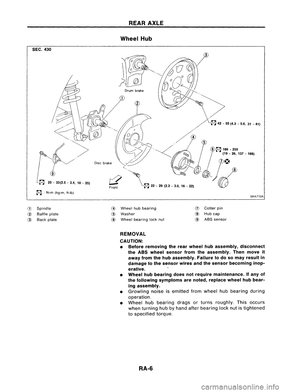
Wheel Hub
SEC. 430
SRA710A
6
~
186 •255
(19 •26, 137 -188)
Drum
brake
r2'\
Front ~22-29 (2.2 •3.0, 16-22)
Disc
brake
25 -33(2.5 -3.4, 18-25)
~ :N.m (kg-m. ft-Ib)
G)
Spindle
@
Baffle plate
@
Back plate
@
Wheel hubbearing
@
Washer
@
Wheel bearing locknut
(J)
Cotter pin
@
Hubcap
@
ABS sensor
REMOVAL
CAUTION:
• Before removing therear wheel hubassembly, disconnect
the ABS wheel sensor fromtheassembly. Thenmove it
away fromthehub assembly. Failuretodo somay result in
damage tothe sensor wiresandthesensor becoming inop-
erative.
• Wheel hubbearing doesnotrequire maintenance. Ifany of
the following symptoms arenoted, replace wheelhubbear-
ing assembly.
• Growling noiseisemitted fromwheel hubbearing during
operation.
• Wheel hubbearing dragsorturns roughly. Thisoccurs
when turning hubbyhand afterbearing locknutistightened
to specified torque.
RA-6
Page 1615 of 1701
SRA711A
SRA712A REAR
AXLE
Wheel Hub(Conl'd)
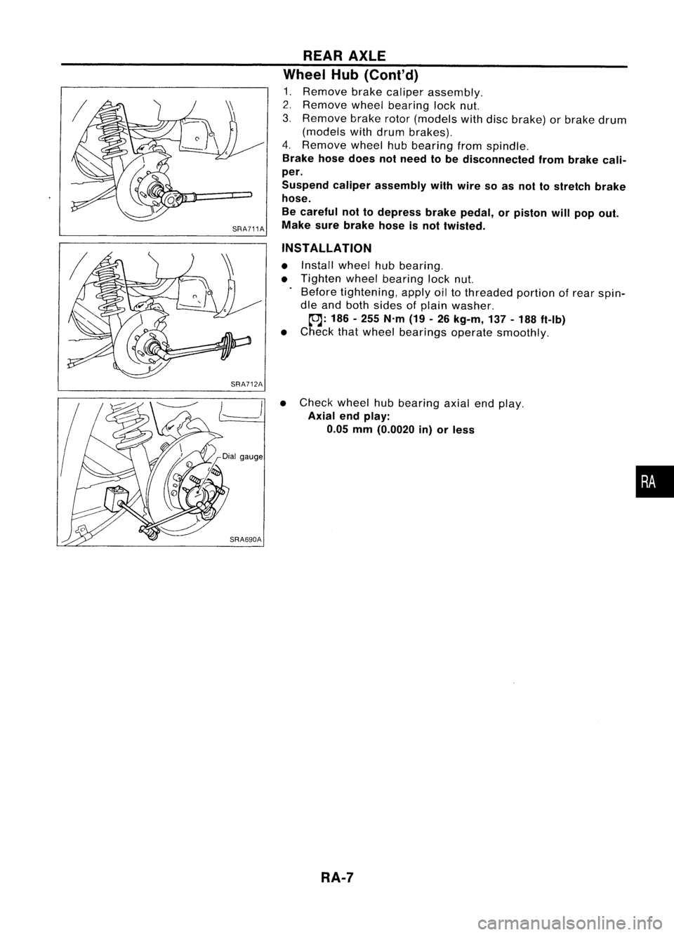
1. Remove brakecaliper assembly.
2. Remove wheelbearing locknut.
3. Remove brakerotor(models withdiscbrake) orbrake drum
(models withdrum brakes).
4. Remove wheelhubbearing fromspindle.
Brake hosedoes notneed tobe disconnected frombrake cali-
per.
Suspend caliperassembly withwire soas not tostretch brake
hose.
Be careful nottodepress brakepedal, orpiston willpop out.
Make surebrake hoseisnot twisted.
INSTALLATION
• Install wheel hubbearing.
• Tighten wheelbearing locknut.
Before tightening, applyoiltothreaded portionofrear spin-
dle and both sides ofplain washer.
~: 186-255 N'm (19-26 kg-m, 137-188 ft-Ib)
• Check thatwheel bearings operatesmoothly.
• Check wheelhubbearing axialendplay.
Axial endplay:
0.05 mm(0.0020 in)orless
RA-7
•
Page 1617 of 1701
SRA696A
SRA697A
S
Control rod
Lateral link
~H";""I"
ITorsion
beam
SRA698AREAR
SUSPENSION
Removal andInstallation
CAUTION:
• Before removing therear suspension assembly,disconnect
the ABS wheel sensor fromtheassembly. Failuretodo so
may result indamage tothe sensor wiresandthesensor
becoming inoperative.
• Remove suspension assembly.
1. Disconnect brakehydraulic linesandparking brakecableat
toggle lever.(Models withdrum brakes.)
• Drain brake fluidbefore disconnecting brakelines.
2. Disconnect parkingbrakecablefromcaliper andremove
brake caliper androtor. (Models withdiscbrakes.)
Suspend caliperassembly withwire soasnot tostretch brake
hose.
Be careful nottodepress brakepedal, orpiston willpop out.
Make surebrake hoseisnot twisted.
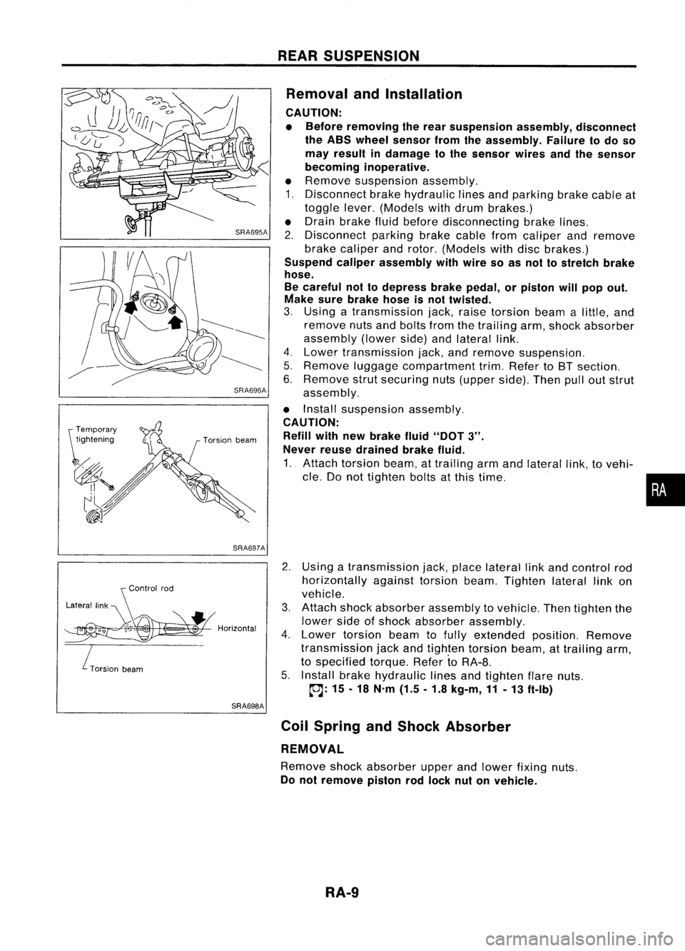
3. Using atransmission jack,raise torsion beamalittle, and
remove nutsandbolts fromthetrailing arm,shock absorber
assembly (lowerside)andlateral link.
4. Lower transmission jack,andremove suspension.
5. Remove luggagecompartment trim.Refer toBT section.
6. Remove strutsecuring nuts(upper side).Thenpulloutstrut
assembly.
• Install suspension assembly.
CAUTION: Refill withnewbrake fluid"DOT
3".
Never reusedrained brakefluid.
1. Attach torsion beam,attrailing armandlateral link,tovehi-
cle. Donot tighten boltsatthis time.
2. Using atransmission jack,place lateral linkand control rod
horizontally againsttorsionbeam.Tighten laterallinkon
vehicle.
3. Attach shockabsorber assembly tovehicle. Thentighten the
lower sideofshock absorber assembly.
4. Lower torsion beamtofully extended position.Remove
transmission jackandtighten torsion beam,attrailing arm,
to specified torque.RefertoRA-8.
5. Install brakehydraulic linesandtighten flarenuts.
~: 15-18 N'm (1.5.1.8 kg-m,11-13 ft-Ib)
Coil Spring andShock Absorber
REMOVAL
Remove shockabsorber upperandlower fixing nuts.
Do not remove pistonrodlock nutonvehicle.
RA-9
•
Page 1620 of 1701
SERVICEDATAANDSPECIFICATIONS (50S)
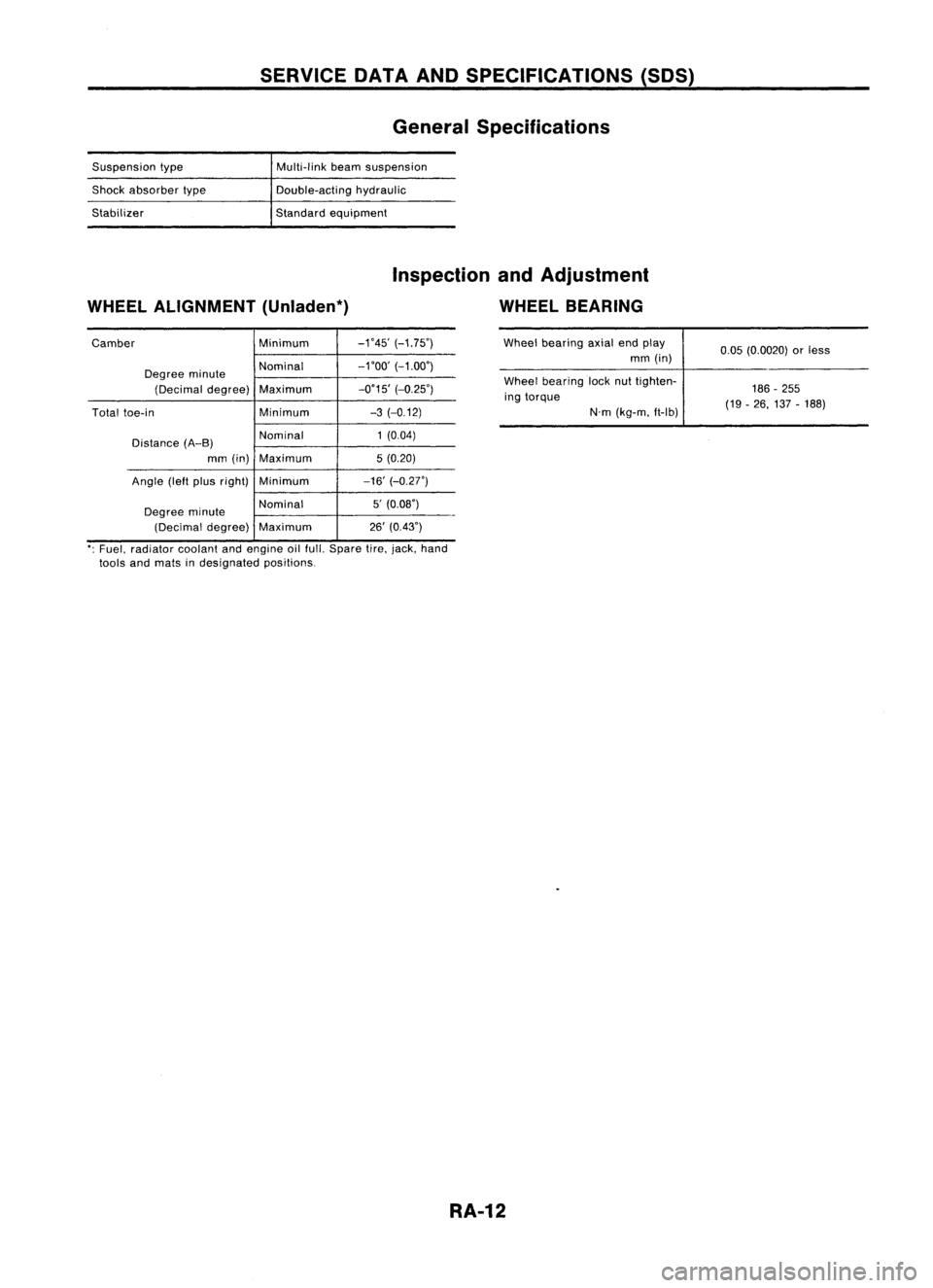
General Specifications
Suspension type
Shock absorber type
Stabilizer Multi-link
beamsuspension
Double-acting hydraulic
Standard equipment
WHEEL ALIGNMENT (Unladen*) Inspection
andAdjustment
WHEEL BEARING
Camber Minimum-1'45'
(-1.75')
Degree minute Nominal
-1'00'
(-1.00')
(Decimal degree) Maximum -0'15'
(-0.25')
Total toe-in Minimum-3
(-0.12)
Distance (A-B) Nominal
1
(0.04)
mm (in) Maximum 5(0.20)
Angle (leftpius right) Minimum -16'(-0.27')
Degree minute Nominal
5'
(0.08')
(Decimal degree)Maximum 26'
(0.43') Wheel
bearing axialendplay
mm (in)
Wheel bearing locknuttighten-
ing torque
N'm(kg-m. ft-lb) 0.05
(0.0020) orless
186 -255
(19 -26, 137 -188)
': Fuel, radiator coolantandengine oilfull. Spare tire.jack, hand
tools andmats indesignated positions.
RA-12
Page 1622 of 1701
PRECAUTION
Supplemental RestraintSystem(SRS)"AIR
BAG" (DualAirBag System)
The Supplemental RestraintSystem"AirBag", usedalong withaseat belt, helps toreduce therisk or
severity ofinjury tothe driver andfront passenger inafrontal collision. TheSupplemental Restraint
System consists ofair bag modules (locatedinthe center ofthe steering wheelandonthe instrument
panel onthe passenger side),adiagnosis sensorunit,warning lamp,wiring harness andspiral cable.
WARNING:
• Toavoid rendering theSRS inoperative, whichcouldincrease therisk ofpersonal injuryordeath
in the event ofacollision whichwould resultinair bag inflation, allmaintenance mustbeperformed
by an authorized NISSANdealer.
• Improper maintenance, includingincorrectremovalandinstallation ofthe SRS, canlead topersonal
injury caused byunintentional activationofthe system.
• Donot use electrical testequipment onany circuit related tothe SRS unless instructed tointhis
Service Manual. SRSwiring harnesses arecovered withyellow insulation eitherjustbefore the
harness connectors orfor the complete harness,foreasy identification.
Supplemental RestraintSystem(SRS)"AIR
BAG" (Single AirBag System)
The Supplemental RestraintSystem"AirBag", usedalong withaseat belt, helps toreduce therisk or
severity ofinjury tothe driver inafrontal collision. TheSupplemental RestraintSystemconsists ofan
air bag module (located inthe center ofthe steering wheel),adiagnosis sensorunit,warning lamp,
wiring harness andspiral cable.
WARNING:
• Toavoid rendering theSRS inoperative, whichcouldincrease therisk ofpersonal injuryordeath
in the event ofacollision whichwould resultinair bag inflation, allmaintenance mustbeperformed
by an authorized NISSANdealer.
• Improper maintenance, includingincorrectremovalandinstallation ofthe SRS, canlead topersonal
injury caused byunintentional activationofthe system.
• Donot use electrical testequipment onany circuit related tothe SRS unless instructed tointhis
Service Manual.
RS-2
Page 1628 of 1701
SUPPLEMENTALRESTRAINTSYSTEM(SRS)
Precautions forSRS "AirBag" and"Seat Belt
Pre-tensioner" Service
• Donot use acircuit testertocheck SRScircuits.
• Before servicing theSRS. turnignition switch"OFF", disconnect bothbattery cablesandwait forat
least 10minutes.
For approximately 10minutes afterthecables areremoved, itis still possible forthe airbag to
deploy. Therefore, donot work onany SRS connectors orwires untilatleast 10minutes havepassed.
• For single airbag system, donot separate diagnosis sensorunitfrom steering wheel.
• For dual airbag system. diagnosis sensorunitmust always beinstalled withtheir arrow marks
"Q"
pointing towards thefront ofthe vehicle forproper operation. Alsocheck diagnosis sensorunitfor
cracks. deformities orrust before installation andreplace asrequired.
• The spiral cablemustbealigned withtheneutral position sinceitsrotations arelimited. Donot
attempt toturn steering wheelorcolumn afterremoval ofsteering gear.
• Handle airbag module carefully. Alwaysplaceitwith thepad side facing upward.
• Donot use oldbolts afterremoving anySRS parts; replace withnewones. Conduct self-diagnosis
to check entire SRSforproper function.
• For dual airbag system, instrument panelassembly shouldbereplaced afterairbag inflates.
X
X
Use
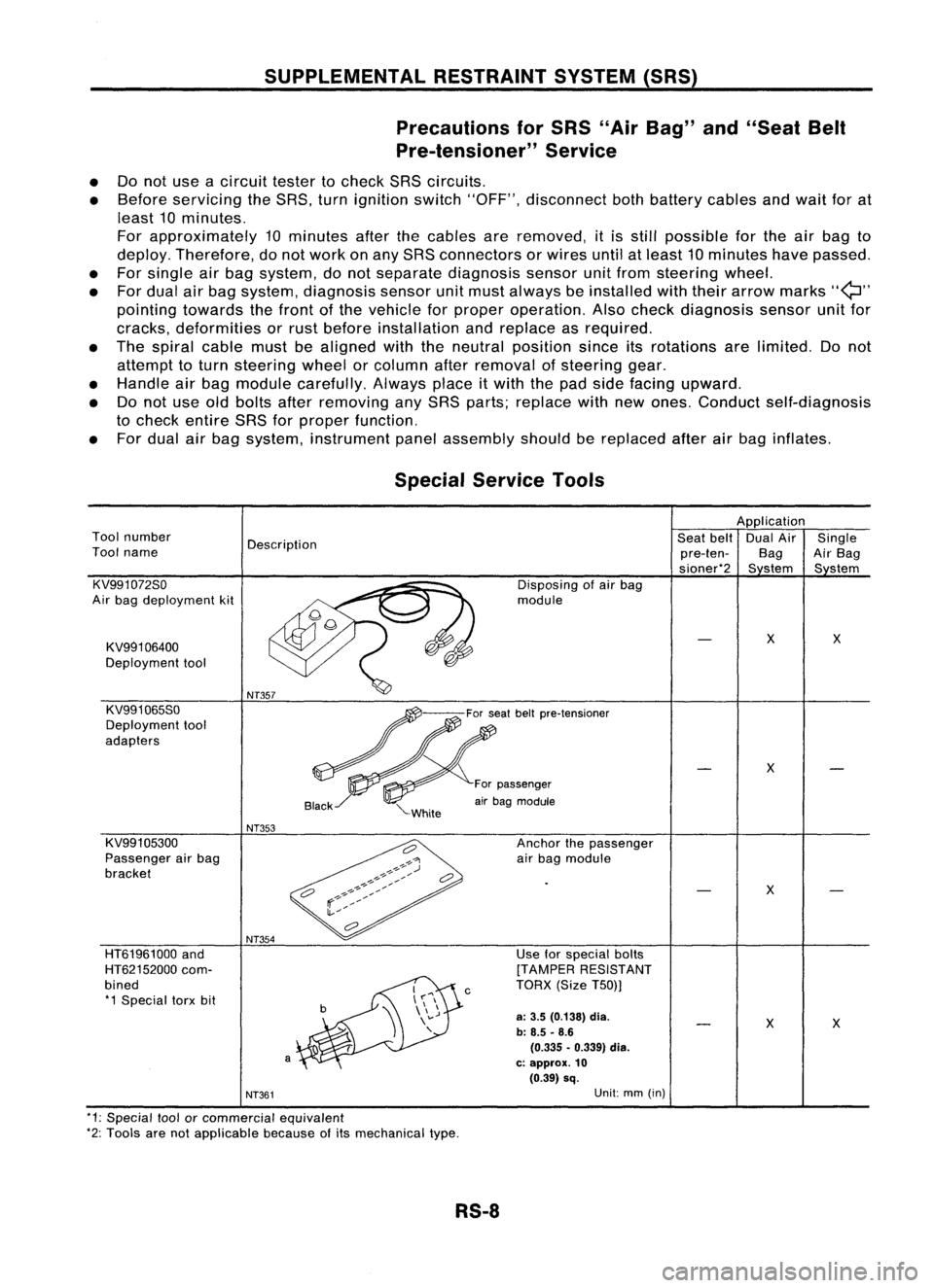
forspecial bolts
[TAMPER RESISTANT
TORX (SizeT50))
a:
3.5 (0.138)
dia.
b: 8.5 -8.6
(0.335 •0.339) dia.
c: approx.
10
(0.39) sq.
c
NT354
a
HT61961000
and
HT62152000 com-
bined *1 Special torxbit
Special
Service Tools
Application
Tool number
Description Seat
belt DualAir Single
Tool name
pre-ten-BagAirBag
sioner*2 Sstem Sstem
KV991072So Disposingofair bag
Air bag deployment kit module
KV991 06400
X
X
Deployment tool
KV991065So
Deployment tool
adapters
X
For passenger
air bag module
NT353
KV991 05300 Anchorthepassenger
Passenger airbag
airbag module
bracket
X
NT361
Unit:
mm(in)
*1: Special toolorcommercial equivalent
*2: Tools arenotapplicable becauseofits mechanical type.
RS-8
Page 1631 of 1701
SUPPLEMENTALRESTRAINTSYSTEM(SRS)
Visually checkSRScomponents
Diagnosis sensorunit
Check diagnosis sensorunitand bracket fordents, cracks
or deformities.
Check connectors fordamage, andterminals fordeformi-
ties.
Air bag module andsteering wheel
Remove airbag module fromsteering wheelorinstrument
panel. Check harness coverandconnectors fordamage,
terminals fordeformities, andharness forbinding.
Install driversideairbag module tosteering wheeltocheck
fit or alignment withthewheel.
Check steering wheelforexcessive freeplay.
For dual airbag system, installpassenger sideairbag
module toinstrument paneltocheck fitor alignment withthe
instrument panel.
Maintenance
Items
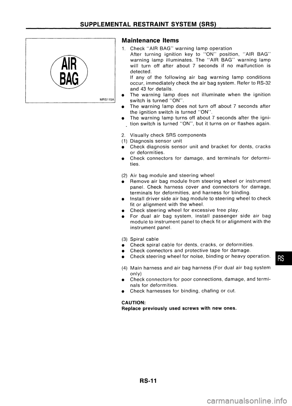
1. Check "AIRBAG" warning lampoperation
After turning ignition keyto"ON" position, "AIRBAG"
warning lampilluminates. The"AIR BAG" warning lamp
will turn offafter about 7seconds ifno malfunction is
detected. If any ofthe following airbag warning lampconditions
occur, immediately checktheairbag system. RefertoRS-32
and 43for details.
The warning lampdoesnotilluminate whentheignition
switch isturned "ON".
The warning lampdoesnotturn offabout 7seconds after
the ignition switchisturned "ON".
The warning lampturns offabout 7seconds aftertheigni-
tion switch isturned "ON",butitturns onorflashes again.
•
MRS115A
•
•
2. (1)
•
•
(2)
•
•
•
•
(3) Spiral cable
• Check spiralcablefordents, cracks, ordeformities.
• Check connectors andprotective tapefordamage.
• Check steering wheelfornoise, binding orheavy operation. •
(4) Main harness andairbag harness (Fordual airbag system
only)
• Check connectors forpoor connections, damage,andtermi-
nals fordeformities.
• Check harnesses forbinding, chafingorcut.
CAUTION: Replace previously usedscrews withnewones.
RS-11
Page 1632 of 1701
SUPPLEMENTALRESTRAINTSYSTEM(SRS)
Removal andInstallation -Diagnosis Sensor
Unit
CAUTION:
• Before servicing SRS,turntheignition switchoff,disconnect bothbattery cablesandwait foratleast
10 minutes.
• The special boltsarecoated withbonding agentwhiletheother boltisfor ground. Donot use old
bolts afterremoval; replacewithnewones.
• For single airbag system, donot separate diagnosis sensorunitfrom steering wheel.
• For dual airbag system, checkdiagnosis sensorunitforproper installation.
• Check diagnosis sensorunittoensure theyarefree ofdeformities, dents,cracks orrust. Ifthey show
any visible signsofdamage, replacethemwithnewones.
• Check diagnosis sensorunitbrackets toensure theyarefree ofdeformities orrust.
• Always workfromtheside ofair bag module.
• Replace diagnosis sensorunitifithas been dropped orsustained animpact.
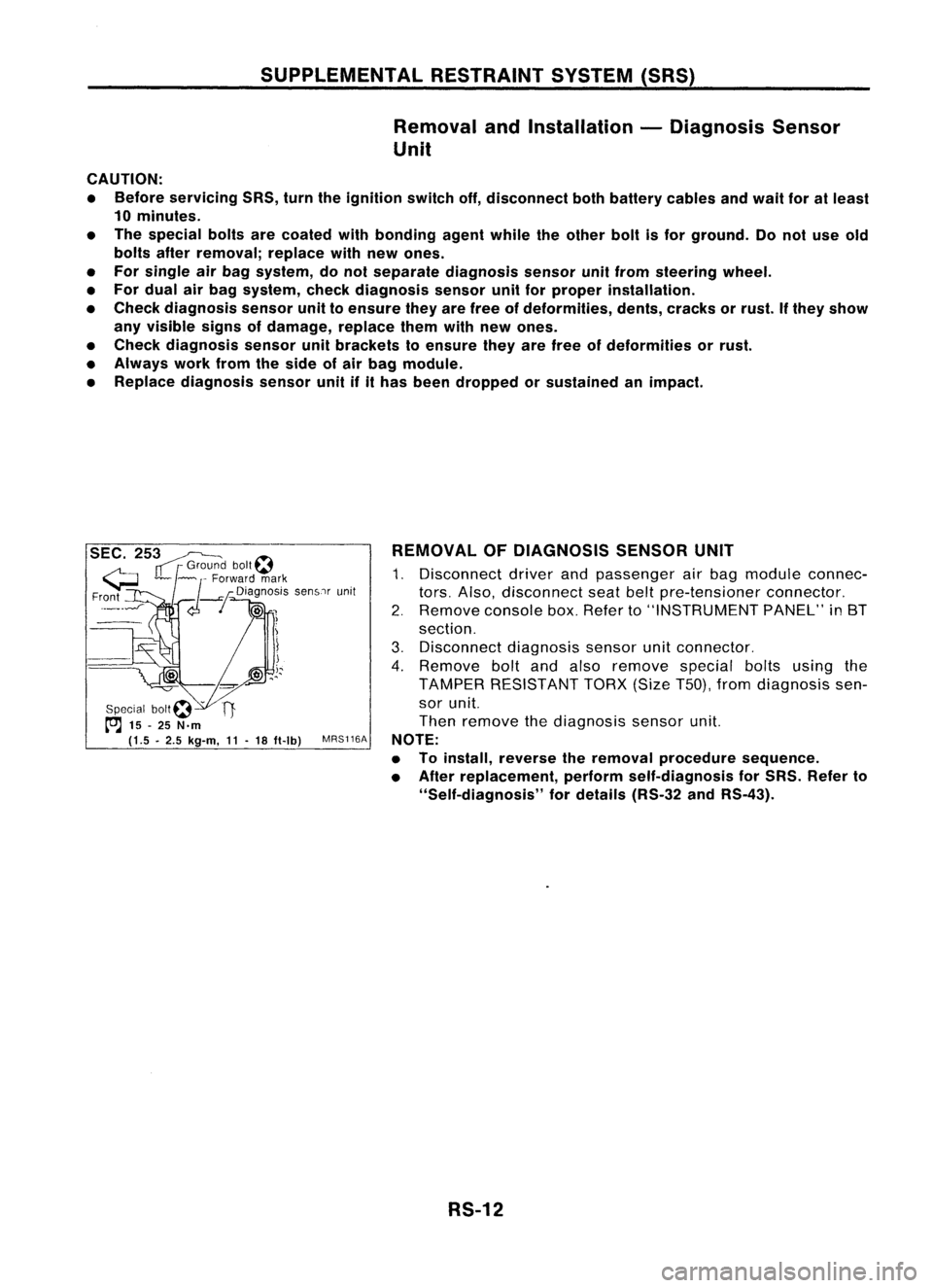
SEC. 253~
IT
r
Grou~? bolt~
G ~~ ~
Forward mark
Fr?nt
_--I
d--!
Dia~no:iS senSlrunit
!
Special bOIt~ -
t"'J
15-25 N.m
(1.5 •2.5 kg-m,
11-
18 ft-Ib)
MRS116A REMOVAL
OFDIAGNOSIS SENSORUNIT
1. Disconnect driverandpassenger airbag module connec-
tors. Also, disconnect seatbeltpre-tensioner connector.
2. Remove consolebox.Refer to"INSTRUMENT PANEL"in8T
section.
3. Disconnect diagnosissensorunitconnector.
4. Remove boltandalso remove specialboltsusing the
TAMPER RESISTANT TORX(SizeT50),fromdiagnosis sen-
sor unit.
Then remove thediagnosis sensorunit.
NOTE:
• Toinstall, reverse theremoval procedure sequence.
• After replacement, performself-diagnosis forSRS. Refer to
"Self-diagnosis" fordetails (RS-32andRS-43).
RS-12