Page 1355 of 1701
GENERALINFORMATION •
SECTION
G
I
CONTENTS
PRECAUTIONS 2
Supplemental RestraintSystem(SRS)"AIR
BAG" (DualAirBag System) 2
Supplemental RestraintSystem(SRS)"AIR
BAG" (Single AirBag System) 2
Precautions forNATS V2.0(ForGasoline
Engine Model) 3
General Precautions 3
Precautions forMultiport FuelInjection
System orECCS Engine 5
Precautions forThree WayCatalyst 5
Engine Oils 5
Precautions forFuel 6
HOW TOUSE THIS
MANUAL 7
HOW TOREAD WIRING DIAGRAMS 9
Sample/Wiring Diagram-EXAMPL - 9
Description 11
Wiring Diagram Codes(CellCodes) 17
HOW TOPERFORM EFFICIENT DIAGNOSIS FOR
AN ELECTRICAL INCIDENT 18
Work Flow 18
Incident Simulation Tests 19
Circuit Inspection 23
HOW
TOFOLLOW FLOWCHART INTROUBLE
DIAGNOSES 29
CONSULT CHECKING SYSTEM
32
Function andSystem Application 32
Lithium BatteryReplacement.. 32
Checking Equipment 32
IDENTIFICATION INFORMATION 33
Model Variation 33
Identification Number 36
Di mens ions 39
Wheels andTires 39
LIFTING POINTSANDTOW TRUCK TOWING ..40
Preparation 40
Board-on
Lift
40
Garage JackandSafety Stand 41
2-pole Lift 42
Tow Truck Towing 43
TIGHTENING TORQUEOFSTANDARD BOLTS
44
SAE J1930 TERMINOLOGY LIST 45
SAE J1930 Terminology List.. 45
Page 1393 of 1701
IDENTIFICATIONINFORMATION
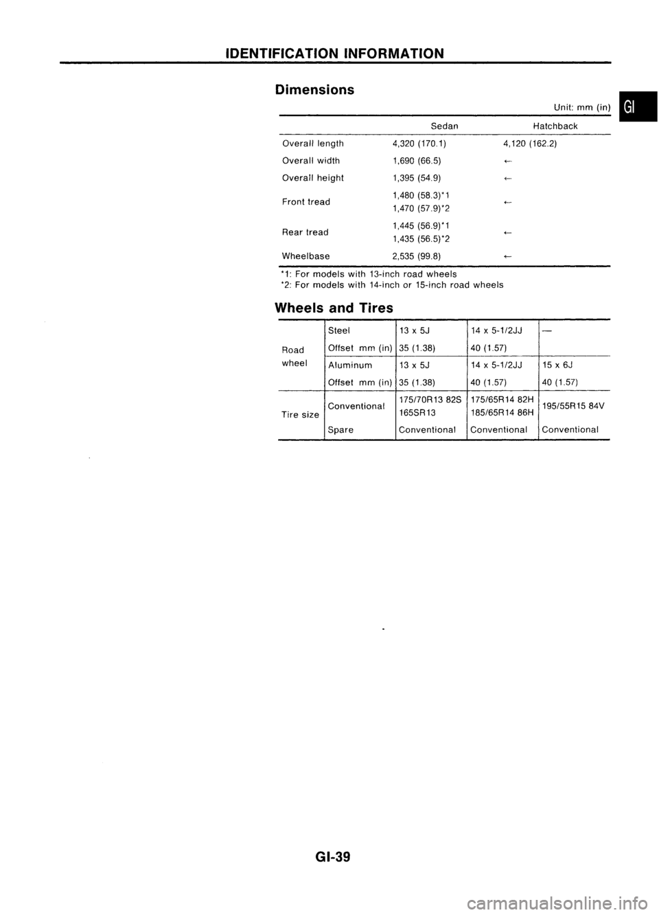
Dimensions SedanUnit:
mm(in) •
Hatchback
Overall length
Overall width
Overall height
Front tread
Rear tread
Wheelbase 4,320
(170.1)
1,690 (66.5)
1,395 (54.9)
1,480 (58.3)* 1
1,470 (57.9)*2
1,445 (56.9)*1
1,435 (56.5)*2
2,535 (99.8) 4,120
(162.2)
*1: For models with13-inch roadwheels
*2: For models with14-inch or15-inch roadwheels
Wheels andTires
Steel 13x5J 14x5-1/2JJ
-
Road Offset
mm(in) 35(1.38) 40(1.57)
wheel Aluminum 13x5J 14
x5-1/2JJ 15x6J
Offset mm(in)
35(1.38) 40
(1.57) 40(1.57)
175170R1382S 175/65R1482H
195/55R1584V
Conventional
185/65R1486H
Tire size 165SR13
Spare Conventional
Conventional Conventional
GI-39
Page 1492 of 1701
GENERALMAINTENANCE
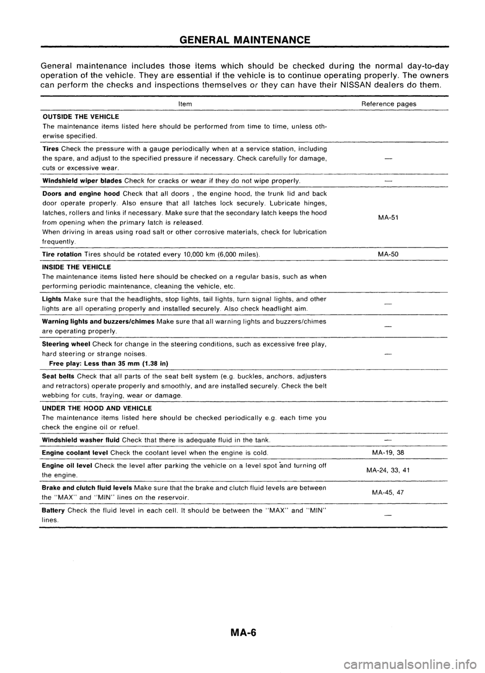
General maintenance includesthoseitemswhich should bechecked duringthenormal day-to-day
operation ofthe vehicle. Theyareessential ifthe vehicle isto continue operating properly.Theowners
can perform thechecks andinspections themselves orthey canhave theirNISSAN dealersdothem.
Item
OUTSIDE THEVEHICLE
The maintenance itemslistedhereshould beperformed fromtimetotime, unless oth-
erwise specified.
Tires
Check thepressure withagauge periodically whenataservice station, including
the spare, andadjust tothe specified pressureifnecessary. Checkcarefully fordamage,
cuts orexcessive wear.
Windshield wiperblades
Checkforcracks orwear ifthey donot wipe properly.
Doors andengine hood
Check thatalldoors, theengine hood,thetrunk lidand back
door operate properly. Alsoensure thatalllatches locksecurely. Lubricate hinges,
latches, rollersandlinks ifnecessary. Makesurethatthesecondary latchkeeps thehood
from opening whentheprimary latchisreleased.
When driving inareas usingroadsaltorother corrosive materials, checkforlubrication
frequently.
Tire rotation
Tiresshould berotated every
10,000
km
(6,000
miles).
INSIDE THEVEHICLE
The maintenance itemslistedhereshould bechecked onaregular basis,suchaswhen
performing periodicmaintenance, cleaningthevehicle, etc.
Lights
Makesurethattheheadlights, stoplights, taillights, turnsignal lights,andother
lights arealloperating properlyandinstalled securely. Alsocheck headlight aim.
Warning lightsandbuzzers/chimes
Makesurethatallwarning lightsandbuzzers/chimes
are operating properly.
Steering wheel
Check forchange inthe steering conditions, suchasexcessive freeplay,
hard steering orstrange noises.
Free play: Lessthan35mm (1.38 in)
Seat belts
Check thatallparts ofthe seat beltsystem (e.g.buckles, anchors, adjusters
and retractors) operateproperly andsmoothly, andareinstalled securely. Checkthebelt
webbing forcuts, fraying, wearordamage.
UNDER THEHOOD ANDVEHICLE
The maintenance itemslisted hereshould bechecked periodically e.g.each timeyou
check theengine oilorrefuel.
Windshield washerfluid
Check thatthere isadequate fluidinthe tank.
Engine coolant level
Check thecoolant levelwhen theengine iscold.
Engine oillevel
Check thelevel afterparking thevehicle onalevel spotandturning off
the engine.
Brake andclutch fluidlevels
Makesurethatthebrake andclutch fluidlevels arebetween
the "MAX" and"MIN" linesonthe reservoir.
Battery
Checkthefluid level ineach cell.Itshould bebetween the"MAX" and"MIN"
lines.
MA-6
Reference
pages
MA-51
MA-50
MA-19,38
MA-24, 33,41
MA-45,47
Page 1536 of 1701
0
0
•
0
0
~ /0
H
H
0
0
(2)
4wheels
5 wheels
SMA785C
Radial
tires
CHASSIS
ANDBODY MAINTENANCE
Tire Rotation
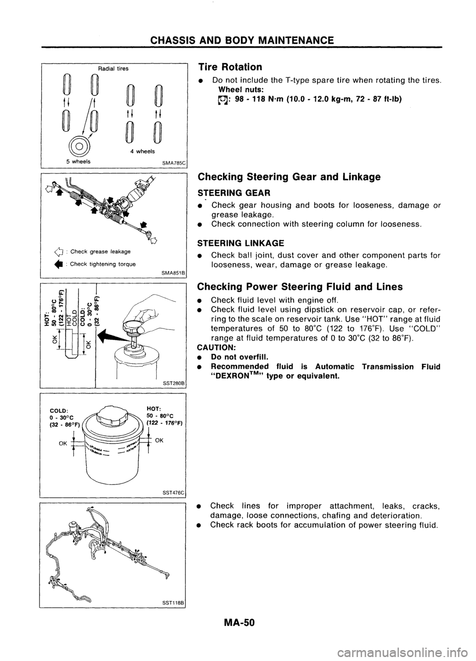
Do not include theT-type sparetirewhen rotating thetires .
Wheel nuts:
~: 98-118 N'm (10.0 -12.0 kg-m, 72-87 ft-Ib)
Q :
Check grease leakage
• :Check tightening torque
Checking
SteeringGearandLinkage
STEERING GEAR
• Check gearhousing andboots forlooseness, damageor
grease leakage.
• Check connection withsteering columnforlooseness.
STEERING LINKAGE
• Check balljoint, dustcover andother component partsfor
looseness, wear,damage orgrease leakage.
SMA851B
Checking PowerSteering FluidandLines
• Check fluidlevel withengine off.
• Check fluidlevel using dipstick onreservoir cap,orrefer-
ring tothe scale onreservoir tank.Use"HOT" rangeatfluid
temperatures of50 to80°C (122to176°F). Use"COLD"
range atfluid temperatures of
a
to 30°C (32to86°F).
CAUTION:
• Donot overfill.
• Recommended fluidisAutomatic Transmission Fluid
''DEXRON™,, typeorequivalent.
SST280B
SST476C
•Check linesforimproper attachment, leaks,cracks,
damage, looseconnections, chafinganddeterioration.
• Check rackboots foraccumulation ofpower steering fluid.
MA-50
Page 1610 of 1701
PRECAUTIONSANDPREPARATION
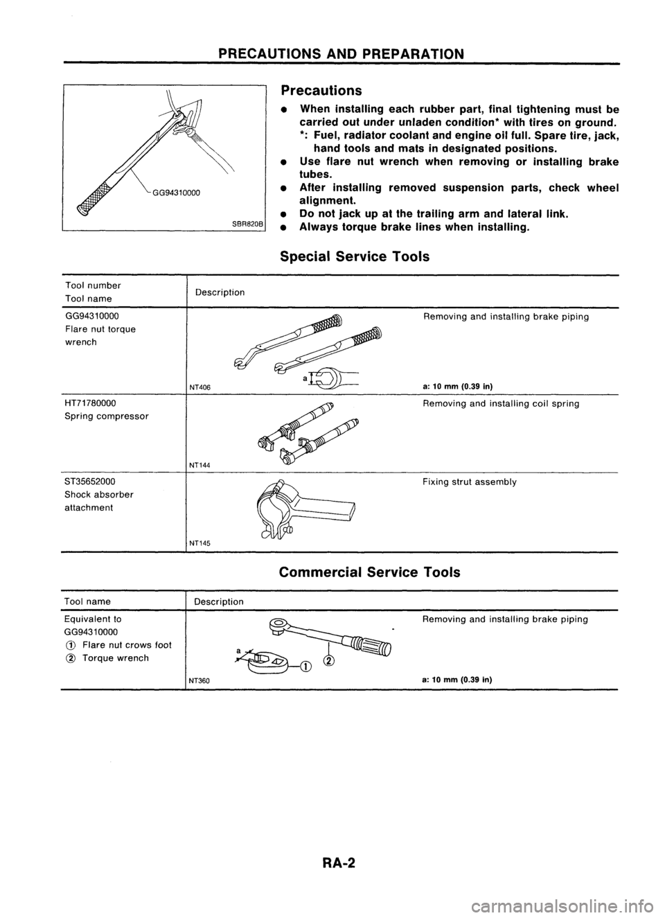
SBR820B Precautions
• When installing eachrubber part,finaltightening mustbe
carried outunder unladen condition* withtires onground.
*:
Fuel, radiator coolantandengine oilfull. Spare tire,jack,
hand tools andmats indesignated positions.
• Use flare nutwrench whenremoving orinstalling brake
tubes.
• After installing removedsuspension parts,check wheel
alignment.
• Donot jack upatthe trailing armandlateral link.
• Always torquebrakelineswhen installing.
Special Service Tools
Tool number
Tool name Description
GG9431 0000
Flare nuttorque
wrench
HT71780000
Spring compressor
ST35652000
Shock absorber
attachment
NT406
NT144
NT145
Removing
andinstalling brakepiping
a:
10
mm
(0.39
in)
Removing andinstalling coilspring
Fixing strutassembly
Tool name
Description
Commercial
ServiceTools
Equivalent to
GG9431 0000
G)
Flare nutcrows
foot
@
Torque wrench Removing
andinstalling brakepiping
NT360
a:
10
mm
(0.39
in)
RA-2
Page 1611 of 1701
REARSUSPENSION SYSTEM
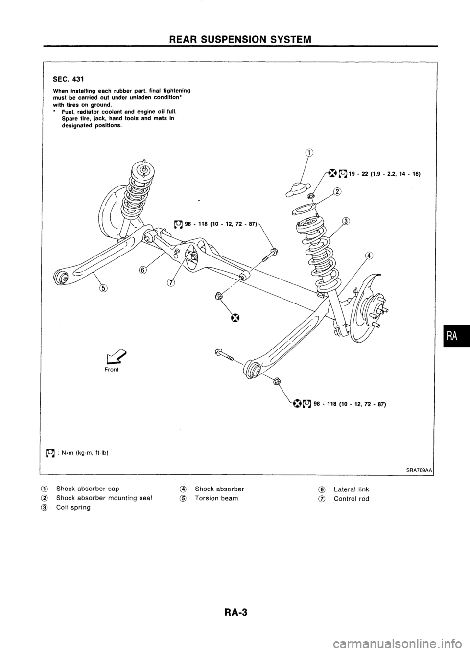
SEC. 431
When installing eachrubber part,finaltightening
must becarried outunder unladen condition'
with tires onground.
, Fuel, radiator coolantandengine oilfull.
Spare tire,lack, handtools andmats in
designated positions.
~ :N.m (kg-m, fHb)
SRA709AA
•
G)
Shock absorber cap
@
Shock absorber mountingseal
@
Coilspring
@
Shock absorber
@
Torsion beam
RA-3 @
Lateral link
(J)
Control rod
Page 1613 of 1701
ON-VEHICLESERVICE
Rear Wheel Alignment
PRELIMINARY INSPECTION
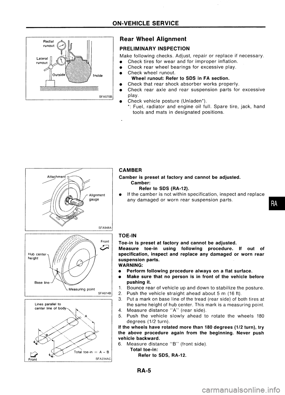
Make following checks.Adjust,repairorreplace ifnecessary.
• Check tiresforwear andforimproper inflation.
• Check rearwheel bearings forexcessive play.
• Check wheelrunout.
Wheel runout: RefertoSOS inFA section.
• Check thatrear shock absorber worksproperly.
• Check rearaxleandrear suspension partsforexcessive
SFA575B
play.
• Check vehicle posture (Unladen*).
*: Fuel, radiator andengine oilfull. Spare tire,jack, hand
tools andmats indesignated positions.
•
CAMBER
Camber ispreset atfactory andcannot beadjusted.
Camber: Refer toSOS (RA-12).
• Ifthe camber isnot within specification, inspectandreplace
any damaged orworn rearsuspension parts.
TOE-IN
Toe-in ispreset atfactory andcannot beadjusted.
Measure toe-inusingfollowing procedure. Ifout of
specification, inspectandreplace anydamaged orworn rear
suspension parts.
WARNING:
• Perform following procedure alwaysonaflat surface.
• Make surethatnoperson isin front ofthe vehicle before
pushing it.
1. Bounce rearofvehicle upand down tostabilize theposture.
2. Push thevehicle straight aheadabout5m (16
ft).
3. Putamark onbase lineofthe tread (rearside) ofboth tires at
the same height ofhub center. Thismark isameasuring point.
4. Measure distance"A"(rear side).
5. Push thevehicle slowlyaheadtorotate thewheels 180
degrees (1/2turn).
If the wheels haverotated morethan180degrees (1/2turn), try
the above procedure againfromthebeginning. Neverpush
vehicle backward.
6. Measure distance"B"(front side).
Total toe-in:
Refer toSOS, RA-12.
Front
SFA948A
SFA614B
SFA234AC
Lines
parallel to
center lineofbOdY~
Q
Front
Hub
center
height
RA-5
Page 1616 of 1701
REARSUSPENSION
SEC. 431
~:N'm (kg-m. fl-Ib)
L'~
~;.;
~~.4,
18 •25)
~'
\ \ i---J
~~ ~
- ~98•118 (
I~ / 110-12,72-87) ~-~~~
@
~
"
\..-~
~ ~;:;:Y ~ '-~.
--...~~ ~~98-118
~ (10-12, 72•87)
~~A
98-118 (10-12, 72-87)
When
installing eachrubber part,finaltightening
must becarried outunder unladen condition"
with tires onground.
" Fuel, radiator coolantandengine allfull.
Spare tire,jack, handtools andmats In~
designated positions. ~
~~ 18.24(1.8.2.4, 13-17)~
~
~A
19•22 (1.9 -2.2, 14•16)~
~
~
~
:\\
\--/
Front
SRA694AA
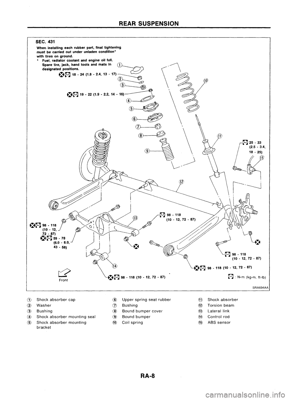
(1)
Shock absorber cap
@
Washer
@
Bushing
@
Shock absorber mounting seal
@
Shock absorber mounting
bracket
@
Upper spring seatrubber
(J)
Bushing
@
Bound bumper cover
@
Bound bumper
@J
Coilspring
Q!J
Shock absorber
@
Torsion beam
@
Lateral link
Q4)
Control rod
@)
ABSsensor
RA-8