Page 598 of 1701
HORN,CIGARETTE LIGHTERANDCLOCK
Wiring Diagram -HORN -
LHD MODELS
EL-HORN-01
HORN
SWITCH
SPIRAL
CABLE
Models
without
air bagsystem
Models withdual
air bagsystem
Models withsingle
air bagsystem
8 *2
AIR BAG
DIAGNOSIS
SENSOR
UNIT
.......
_-.",.
RE-
LEASED
@:
@:
@:
HORN
SWITCH
SPIRAL
CABLE
em
'---"
RE-
LEASED
G/Y
m~
BATTERY
]
10A RefertoEL-POWER.
1421
G/B
g
2
HORN
~ RELAY
~1bjJl@
G G/Y
I----,O'----O~:------I
AN
!
~ G/Y
G /Y
r:::!::.
11tJ1~
11711
G/Y
......,~
I!:i=ll@
G/Y
~
T'---I
G G
QJ1 QJ1
HORN HORN
(LOW) (HIGH)
~ ~
ffim
[ill]
W
@
W
I:I[Q:TI:ICID
~W
DIDdZl
~BR
Refer
tolast page
(Foldout page).
FI ~ ~
(ffiJ)
L!J
B'B 'B
~*1
c:IIJgI
B
~*2
~W
HEL132
EL-226
Page 599 of 1701
HORN,CI(;ARETTE LIGHTERANDCLOCK
Wiring Diagram -HORN -(Cont'd)
EL-HORN-02
•
FUSE
Referto
BLOCK EL-POWER.
(JIB)
~
Refer tolast page
(Foldout page).
COMBINATION
METER
@
~
7.5A
1241
~
BIR
P
IF!4il
BIR
!
@)
OIGITAL
CLOCK
15A
[]Q]
CLOCK ILLUMI-
NATION
L
~
~ B
•
CIGARETTE
LIGHTER SOCKET
@
15A
[TI]
r-----------------------------------,
1ITl~
[]] B
@:
Withtachometer
@:
Without tachometer
*3"'@ 34
@
5
*4 ... @28
'@
6
*5' ..@29
'@10
*6"'@ 9
'@31
,
I
N;.21
OR/B
I
CIGARETTE OR/B
LIGHTER ~
~ 10-----.:
~B
l-,
I
B B
~1
ffi
JOINT
CONNECTOR-1
~
Ibi=Jl
B
I
f,
B B
! !
(M28) (M68)
L ~
IIIIIillIITillI
@
~BR
HEL133
EL-227
Page 600 of 1701
HORN,CIGARETTE LIGHTERANDCLOCK
Wiring Diagram -HORN -(ConI' d)
RHO
MODELS
EL-HORN-03
HORN
SWITCH
SPIRAL
CABLE
Models
without
air bagsystem
Models withdual
air bagsystem
Models withsingle
air bagsystem
B *2
AIR BAG
DIAGNOSIS
SENSOR
UNIT
.......
_-"
RE-
LEASED
@:
@:
@:
HORN
SWITCH
SPIRAL
CABLE
ill)
......
_-"
RE-
LEASED
G/Y
m
G/B
g
2
HORN
~ RELAY
~4=HID
G G/Y
I----IO----.O~ ..
------I
AN. G/Y
G/Y ~
~~ Ifill
I~I
G/Y
1~IU6~
G/Y
rn
'---I
G G
QJ1 QJ1
HORN HORN
(LOW) (HIGH)
m rn
mID
[ill]
W
@
W
~
ill)
DID"JZl
108)
~W ~BR
Refer
tolast page
(Fo ldout page).
F.1
rn m
l..!.J
B' B'B
~
*1
IT:I::illl
8
~*2
~W
HEL134
EL-228
Page 601 of 1701
HORN,CIGARETTE LIGHTERANDCLOCK
Wiring Diagram -HORN -(Cont'd)
EL-HORN-04
•
Refer
tolast page
(Foldout page).
FUSE
Referto
BLOCK EL-POWER.
(JIB)
([@
COMBINATION
METER
~
7.5A
1241
~
B/R
@: For
Europe
@:
Except forEurope
@: With
tachometer
@:
Without tachometer
*3"'@ 34
@
5
*4 ... @
28
'
6
B/R
,
*5"'@ 29
10
1
*6"'@
9
'
31
,
*7"'@ B
@
BR/Y
,
DIGITAL
CLOCK
15A
[]Q]
CLOCK ILLUMI-
NATION
Toillumination
control SWitch
-------II-BR/Y+
(Viajoint
connector-5)
(Refer toEL-ILL.)
CIGARETTE
LIGHTER
SOCKET
~
15A
mJ
r-----------------------------------,
[[il~
rn
B
CIGARETTE
LIGHTER
~ 10-----,- ,
~ B
L, ~
~o.:i
JOINT
CONNECTOR-1
~
~ B
I
" n
B
BBB
1
!..J
1
(M28) (M60) (M68)
L ~
I1IIIIIillIillI ~
~BR
HEL135
EL-229
Page 1371 of 1701

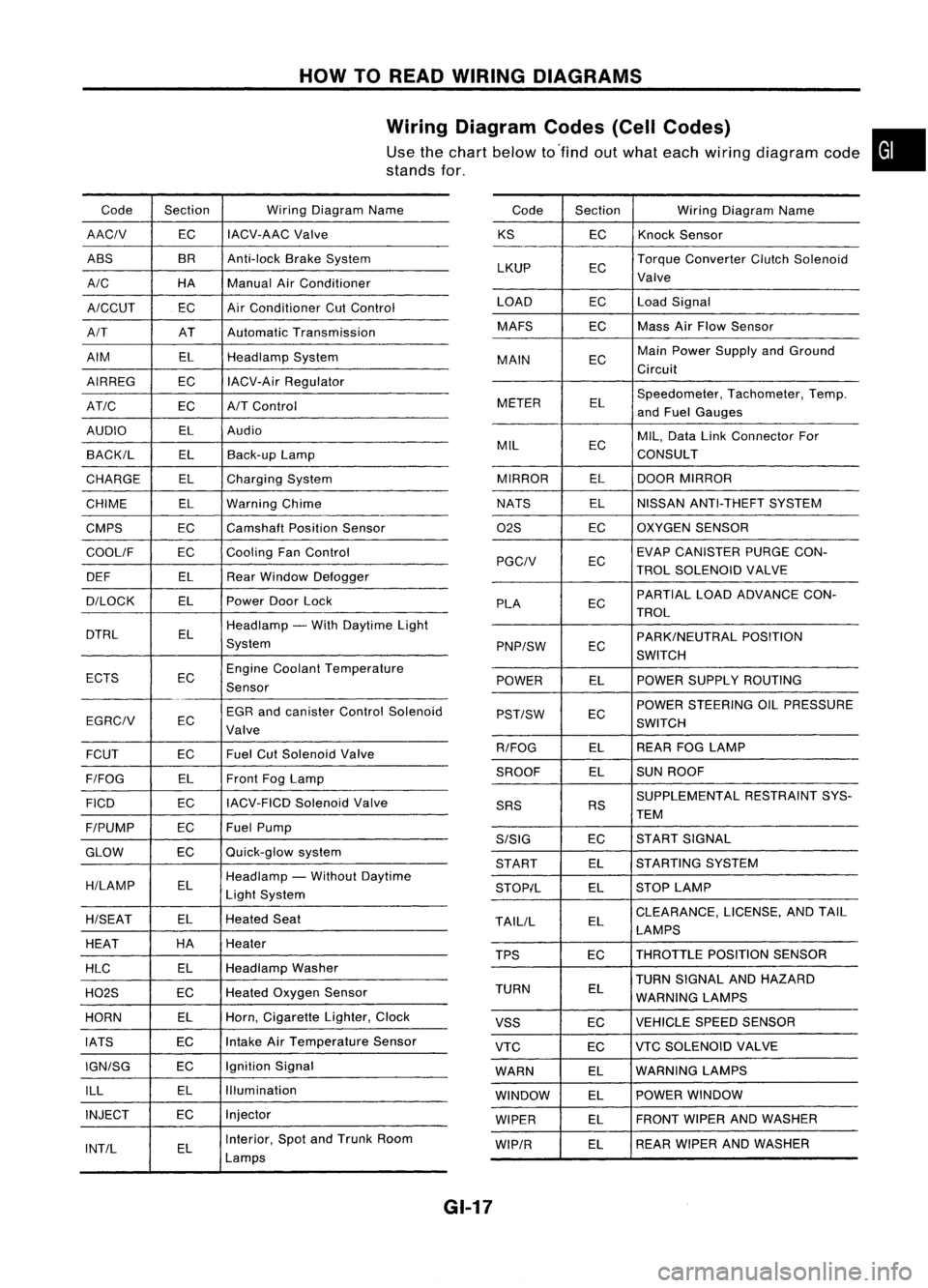
HOWTOREAD WIRING DIAGRAMS
Wiring Diagram Codes(CellCodes)
Use thechart below to'find outwhat each wiring diagram code•
stands for,
Code Section WiringDiagram Name
AACIV ECIACV-AAC
Valve
ABS BR
Anti-lock BrakeSystem
A/C HAManualAirConditioner
A/CCUT ECAir
Conditioner CutControl
A/T ATAutomatic Transmission
AIM ELHeadlamp System
AIRREG ECIACV-Air Regulator
AT/C ECA/TControl
AUDIO ELAudio
BACK/L ELBack-up Lamp
CHARGE ELCharging System
CHIME ELWarning Chime
CMPS EC
Camshaft PositionSensor
COOllF ECCooling
FanControl
DEF ELRearWindow Defogger
D/LOCK ELPowerDoorLock
DTRL ELHeadlamp
-With Daytime Light
System
ECTS ECEngine
Coolant Temperature
Sensor
EGR andcanister ControlSolenoid
EGRCIV EC
Valve
FCUT ECFuel
CutSolenoid Valve
F/FOG ELFront
FogLamp
FICO ECIACV-FICD
SolenoidValve
F/PUMP ECFuel
Pump
GLOW ECQuick-glow
system
H/LAMP ELHeadlamp
-Without Daytime
Light System
H/SEAT ELHeated
Seat
HEAT HA
Heater
HLC ELHeadlamp
Washer
H02S ECHeated
Oxygen Sensor
HORN ELHorn,
Cigarette Lighter,Clock
IATS ECIntake
AirTemperature Sensor
IGN/SG ECIgnition
Signal
ILL ELIllumination
INJECT ECInjector
INT/L ELInterior,
SpotandTrunk Room
Lamps Code
Section WiringDiagram Name
KS ECKnock
Sensor
LKUP ECTorque
Converter ClutchSolenoid
Valve
LOAD ECLoadSignal
MAFS ECMass
AirFlow Sensor
MAIN ECMain
Power Supply andGround
Circuit
METER ELSpeedometer,
Tachometer,Temp.
and Fuel Gauges
MIL ECMIL,
Data LinkConnector For
CONSULT
MIRROR ELDOOR
MIRROR
NATS ELNISSAN
ANTI-THEFT SYSTEM
02S ECOXYGEN
SENSOR
EC EVAP
CANISTER PURGECON-
PGCIV TROLSOLENOID VALVE
PLA ECPARTIAL
LOADADVANCE CON-
TROL
EC PARK/NEUTRAL
POSITION
PNP/SW SWITCH
POWER ELPOWER
SUPPLY ROUTING
POWER STEERING OILPRESSURE
PST/SW EC
SWITCH
R/FOG ELREAR
FOGLAMP
SROOF ELSUN
ROOF
SUPPLEMENTAL RESTRAINTSYS-
SRS RS
TEM
S/SIG ECST
ART SIGNAL
START ELSTARTING
SYSTEM
STOP/L ELSTOP
LAMP
TAllIL ELCLEARANCE,
LICENSE,ANDTAIL
LAMPS
TPS ECTHROTTLE
POSITIONSENSOR
TURN SIGNAL ANDHAZARD
TURN EL
WARNING LAMPS
VSS ECVEHICLE
SPEEDSENSOR
VTC ECVTC
SOLENOID VALVE
WARN ELWARNING
LAMPS
WINDOW ELPOWER
WINDOW
WIPER ELFRONT
WIPERANDWASHER
WIP/R ELREAR
WIPER ANDWASHER
GI-17
Page 1491 of 1701

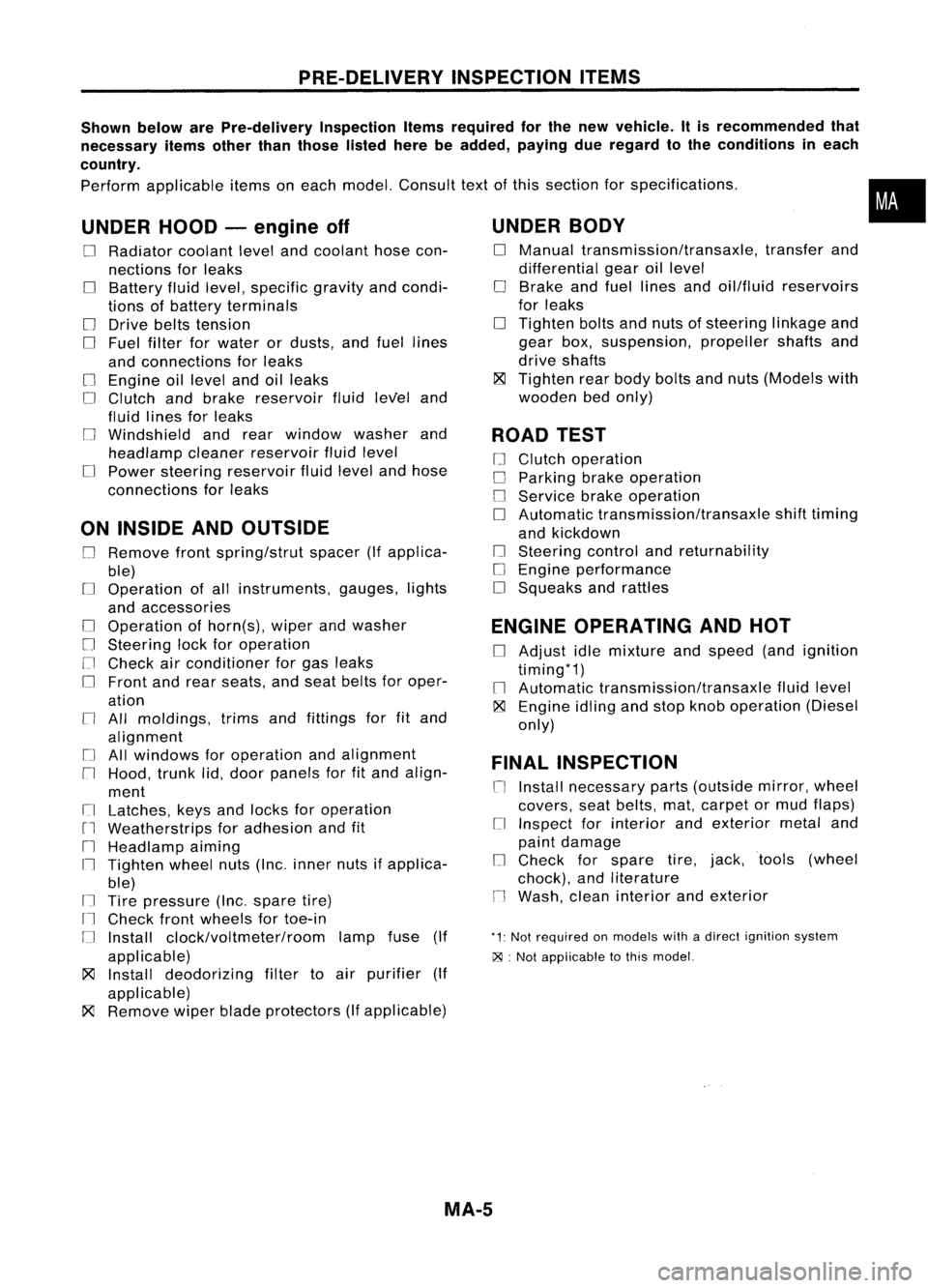
PRE-DELIVERYINSPECTIONITEMS
Shown belowarePre-delivery InspectionItemsrequired forthe new vehicle. Itis recommended that
necessary itemsotherthanthose listedherebeadded, payingdueregard tothe conditions ineach
country.
Perform applicable itemsoneach model. Consult textofthis section forspecifications .
UNDER HOOD-engine off
o
Radiator coolantlevelandcoolant hosecon-
nections forleaks
o
Battery fluidlevel, specific gravityandcondi-
tions ofbattery terminals
o
Drive beltstension
D
Fuel filter forwater ordusts, andfuel lines
and connections forleaks
[] Engine oillevel andoilleaks
D
Clutch andbrake reservoir fluidlevel and
fluid lines forleaks
o
Windshield andrear window washerand
headlamp cleanerreservoir fluidlevel
D
Power steering reservoir fluidlevel andhose
connections forleaks
ON INSIDE ANDOUTSIDE
D
Remove frontspring/strut spacer(Ifapplica-
ble)
D
Operation ofall instruments, gauges,lights
and accessories
o
Operation ofhorn(s), wiperandwasher
[] Steering lockforoperation
[] Check airconditioner forgas leaks
o
Front andrear seats, andseat belts foroper-
ation
n
All moldings, trimsandfittings forfitand
alignment
[J
Allwindows foroperation andalignment
n
Hood, trunklid,door panels forfitand align-
ment
[1
Latches, keysandlocks foroperation
rl
Weatherstrips foradhesion andfit
[l
Headlamp aiming
I~ Tighten wheelnuts(Inc. inner nutsifapplica-
ble)
IJ Tire pressure (Inc.spare tire)
Il
Check frontwheels fortoe-in
IJ Install clock/voltmeter/room lampfuse(If
applicable)
~ Install deodorizing filtertoair purifier (If
applicable)
~ Remove wiperbladeprotectors (Ifapplicable)
UNDER
BODY
o
Manual transmission/transaxle, transferand
differential gearoillevel
D
Brake andfuel lines andoil/fluid reservoirs
for leaks
D
Tighten boltsandnuts ofsteering linkageand
gear box,suspension, propellershaftsand
drive shafts
~ Tighten rearbody boltsandnuts (Models with
wooden bedonly)
ROAD TEST
D
Clutch operation
D
Parking brakeoperation
[J
Service brakeoperation
D
Automatic transmission/transaxle shifttiming
and kickdown
[] Steering controlandreturnability
o
Engine performance
D
Squeaks andrattles
ENGINE OPERATING ANDHOT
D
Adjust idlemixture andspeed (andignition
timing*1)
n
Automatic transmission/transaxle fluidlevel
~ Engine idlingandstop knob operation (Diesel
only)
FINAL INSPECTION
n
Install necessary parts(outside mirror,wheel
covers, seatbelts, mat,carpet ormud flaps)
[1
Inspect forinterior andexterior metaland
paint damage
[] Check forspare tire,jack, tools (wheel
chock), andliterature
n
Wash, cleaninterior andexterior
"1: Not required onmodels withadirect ignition system
~ :Not appiicable tothis model.
•
MA-5
Page 1634 of 1701
SUPPLEMENTALRESTRAINTSYSTEM(SRS)
Removal andInstallation -Air Bag Module and
Spiral Cable(DualAirBag System)
SEC. 253-484
Horn relayswitch connector
Special bolt~
to:J
15-25 (1.5 -2.5,
11-
18)
to:J :
N.m (kg-m. ft-Ib) Special
bolt~
to:J
15.25 (1.5•2.5,
11•
18)
Side lidRH
Air bag module
to:J
29-39 (3.0 -4.0, 22-29)
Lower lid
MRS118A
Removal andInstallation -Air Bag Module and
Spiral Cable(Single AirBag System)
SEC. 253-484
Airbag module connector
Spiral cable
A'
Special bolt~ ~
t"J
15•25 (1.5 •2.5, 11•18)- ~
Side lidLH/
"-J
to:J :
N. m (kg-m. ft-Ib) ~DiagnOSiS
sensorunit
(Do notseparate thediagnosis
sensor unitfrom steering wheel.)
Special boll~
to:J
15-25 (1.5 -2.5,
11-
18)
~~ r
S;d, lidRH
~ (]A;,b'9
mod",
MRS119A
RS-14
Page 1635 of 1701

SUPPLEMENTALRESTRAINTSYSTEM(SRS)
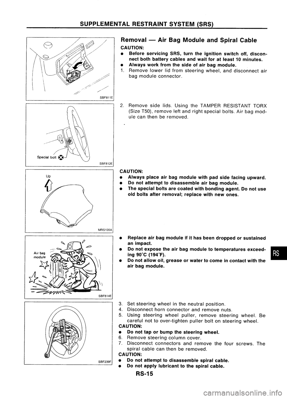
Removal -Air Bag Module andSpiral Cable
CAUTION:
• Before servicing SRS,turntheignition switchoff,discon-
nect both battery cablesandwait foratleast 10minutes.
• Always workfromtheside ofair bag module.
1. Remove lowerlidfrom steering wheel,anddisconnect air
bag module connector.
SBF811E
2.Remove sidelids.Using theTAMPER RESISTANT TORX
(Size T50), remove leftand right special bolts.Airbag mod-
ule can then beremoved.
SBF812E CAUTION:
• Always placeairbag module withpadside facing upward.
• Donot attempt todisassemble airbag module.
• The special boltsarecoated withbonding agent.Donot use
old bolts afterremoval; replacewithnew ones.
MRS120A
Air bag
module
SBF814E•
•
• Replace
airbag module ifithas been dropped orsustained
an impact.
Do not expose theairbag module totemperatures exceed-•
•
ing 90°C (194°F).
Do not allow oil,grease orwater tocome incontact withthe
air bag module.
SBF239F
3.
Set steering wheelinthe neutral position.
4. Disconnect hornconnector andremove nuts.
5. Using steering wheelpuller, remove steering wheel.Be
careful nottoover-tighten pullerboltonsteering wheel.
CAUTION:
• Donot tap orbump thesteering wheel.
6. Remove steering columncover.
7. Disconnect connectorsandremove thefour screws. The
spiral cablecanthen beremoved.
CAUTION:
• Donot attempt todisassemble spiralcable.
• Donot apply lubricant tothe spiral cable.
RS-15