Page 52 of 1701
Model
34X68
SAT496HB
SAT0170
DISASSEMBL
Y
b. Remove stopperringfrom terminal body.
c. Push terminal bodyintotransmission caseanddraw out
solenoid harness.
10. Remove manualvalvefromcontrol valveassembly.
11. Remove returnspring fromSIRaccumulator piston.
12. Remove SIRaccumulator pistonwithcompressed air.
13. Remove O-ringsfromSIRaccumulator piston.
AT-52
Page 61 of 1701
Parkingshaft
SAT064D
SAT702D DISASSEMBL
V
44. Remove forwardclutchassembly fromtransmission case.
45. Remove thrustwasher andbearing racefrom transmission
case.
- All models - •
46. Remove returnspring fromparking shaftusing ascrew-
i
driver.
- Except model34X81-
47. Remove outputshaft,output gearandreduction piniongear
according tothe following procedures.
a. Remove sidecover.
• Donot reuse sidecover bolts.
b. Set manual leverto"p" position tofix idler gear andout-
put gear.
c. Unlock bothidlergear andoutput gearlocknuts using apin
punch.
AT-61
Page 66 of 1701
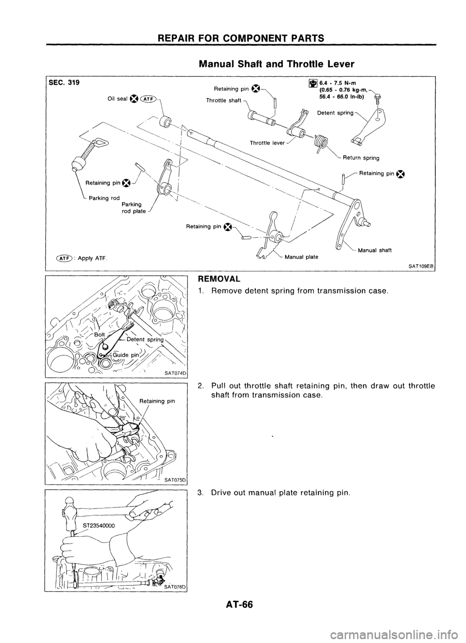
SEC.319
c&D:
ApplyATF. REPAIR
FORCOMPONENT PARTS
Manual ShaftandThrottle Lever
~ 6.4•7.5 N.m
Retaining pm~~ (0.65-0.76 kg-m. "-
Throttle shaft ~ 56.4-66.0 In-Ib)
f
~ 0.""
''''0'''11)
Th""'. ,,~,/ ,
V
~ Return spnng
~ Retaining pin~
)
SAT109EB
REMOVAL
1. Remove detentspringfromtransmission case.
2. Pullout throttleshaftretaining pin,then draw outthrottle
shaft fromtransmission case.
3. Drive outmanual plateretaining pin.
AT-66
Page 67 of 1701
REPAIRFORCOMPONENT PARTS
Manual ShaftandThrottle Lever(ConI'd)
4. Drive andthen pulloutparking rodplate retaining pin.
5. Remove parkingrodplate frommanual shaft.
6. Draw outparking rodfrom transmission case.
7. Pull outmanual shaftretaining pin. •
8. Remove manualshaftandmanual platefromtransmission
i
case.
9. Remove manualshaftoilseal.
SATOBOD
INSPECTION
• Check component partsforwear ordamage. Replaceif
necessary.
AT-67
Page 68 of 1701
REPAIRFORCOMPONENT PARTS
Manual ShaftandThrottle Lever(Cont'd)
INSlALLA liON
1. Install manual shaftoilseal.
• Apply ATFtoouter surface ofoil seal.
2. Install throttle leverandreturn spring onthrottle shaft.
3. Install throttle leverassembly ontransmission case.
4. Align groove ofthrottle shaftandhole oftransmission case.
5. Install throttle shaftretaining pin.
6. Move throttle leverinthe direction ofthe arrow.
7. Install manual shaftandmanual plate.
8. Align groove ofmanual shaftandhole oftransmission case.
9. Install manual shaftretaining pin.
AT-68
Page 161 of 1701
\~~~~~C0\
~~ \.---.!
~ />"0
o
<=~~ )'()
Throttle lever'~ ~\
~ Il';-,~\ ,~\\)
,./, Manual plate
2\ (
. ~ -P-' (\
d (
Detent valve
/- \, 'sdJ :----, \,,,
n\ ';\ ~ "~
Manualvalve
\3l~w1:
nd\'~~\ \\)~
\(--' "'!f ()~
r:,
A~
\ ~ SAT414D
SAT664D ASSEMBLY
Assembly 4(Conl'd)
b, Set manual shaftinNeutral position.
c. Install control valveassembly ontransmission casewhile
aligning manualvalvewithmanual plateanddetent valve
with throttle lever.
d. Pass solenoid harnessthroughtransmission caseand
install terminal bodyontransmission casebypushing
it.
e. Install cliptoterminal body.
f.
Tighten bolts@,
@. ~
and
@.
Bolt length, number andlocation:
Bolt
@
@ @
@
Bolt length
'T'
mm
(in)
33,0
40,0
43,525,0
(1.299) (1.575)(1,713)
(0.984)
Number ofbolts
652
2
Tightening torque
7-9 (0,7 -0.9, 61-78)
N'm (kg-m, in-Ib)
12. Install oilpan.
a. Attach magnet tooil pan.
AT-161
•
Page 163 of 1701
SAT620E
SAT586H
SAT428DA
Torque
converter
ASSEMBLY
Assembly 4(Cont'd)
14. Install inhibitor switch.
a. Set manual shaftin"P" position.
b. Temporarily installinhibitor switchonmanual shaft.
c.
Move
selector
lever
to"N" position.
d. Use a4mm (0.157 in)pin forthis adjustment.
1) Insert thepinstraight intothemanual shaftadjustment hole.
2) Rotate inhibitor switchuntilthepincan also beinserted
straight intohole ininhibitor switch.
e. Tighten inhibitor switchfixingbolts.
f. Remove pinfrom adjustment holeafter adjusting inhibitor
switch.
15. Install oilcharging pipeandoilcooler tubetotransmission •
case.
16. Install torque converter.
a. Pour ATFintotorque converter.
• Approximately 1liter (7/8Impqt)offluid isrequired fora
new torque converter.
• When reusing oldtorque converter, addthesame amount
of fluid aswas drained.
b. Install torque converter whilealigning notchesoftorque
converter withnotches ofoil pump.
AT-163
Page 1361 of 1701

HOWTOUSE THIS MANUAL
•
•
•
•
•
•
ALPHABETICAL
INDEXisprovided atthe end ofthis manual sothat youcan rapidly findtheitem •
and page youaresearching for.
A QUICK REFERENCE INDEX,ablack tab(e.g.
I=J;J)
is provided onthe first page. Youcanquickly
find thefirst page ofeach section bymating itto the section's blacktab.
THE CONTENTS arelisted onthe first page ofeach section .
THE TITLE isindicated onthe upper portion ofeach pageandshows thepart orsystem .
THE PAGE NUMBER ofeach section consists oftwo letters whichdesignate theparticular section
and anumber (e.g."BR-5").
THE LARGE ILLUSTRATIONS areexploded views(Seebelow) andcontain tightening torques,lubri-
cation points, section number ofthe PARTS CATALOG (e.g.SEC.440) andother information neces-
sary toperform repairs.
The illustrations shouldbeused inreference toservice matters only.When ordering parts,referto
the appropriate PARTSCATALOG.
"Example"
SEC. 440
~~Copper washer
~ /~17-20
<~ ~~
(1.7-2.0, 12•14)
,~
'(~
,
i"::
I
cftJ ~
Brake hose
~ ~Air bleeder
V
1111
7•9 (0.7 -0.9, 61-78)
Pin bolt
~ 22-31 (2.2 -3.2, 16•23)
-Cylinder body~-~
Piston sealm~
Piston
I] ~:
N.m(kg-m, ft-Ib)
It].
N'm(kg-m, in-Ib)
SBR364AC
Outer
shim
Torque
member
Pad
retainer
(Upper side)
1]\
~ jL"J
54... 1'5•'.5, 40•
'71
/~ ~D Mainpin
/ mtosliding portion
o ~
D
~ ~
----------
Pad retainer ~
(Lower Side)m~
• THE SMALL ILLUSTRATIONS showtheimportant steps-suchasinspection, useofspecial tools,
knacks ofwork andhidden ortricky stepswhich arenotshown inthe previous largeillustrations.
Assembly, inspectionandadjustment procedures forthe complicated unitssuchasthe automatic
transaxle ortransmission, etc.arepresented inastep-by-step formatwherenecessary.
GI-7


4. Drive andthen pulloutparking rodplate retaining pin.
5. Remove parkingrodplate frommanual shaft.
6. Draw outparking rodfrom trans")

INSlALLA liON
1. Install manual shaftoilseal.
• Apply ATFtoouter surface ofoil seal.
2. Install throttle leverandreturn spring")
'()
Throttle lever'~ ~\
~ Il';-,~\ ,~\\)
,./, Manual plate
2\ (
. ~ -P-' (\
d (
Detent valve
/- \, 'sdJ :----, \,,,
n\ ';\ ~ &")

14. Install inhibitor switch.
a. Set manual shaftin\"P\" position.
b. Temporarily installinhibitor switchonmanual sha")