1995 NISSAN ALMERA N15 Manual trans
[x] Cancel search: Manual transPage 1362 of 1701
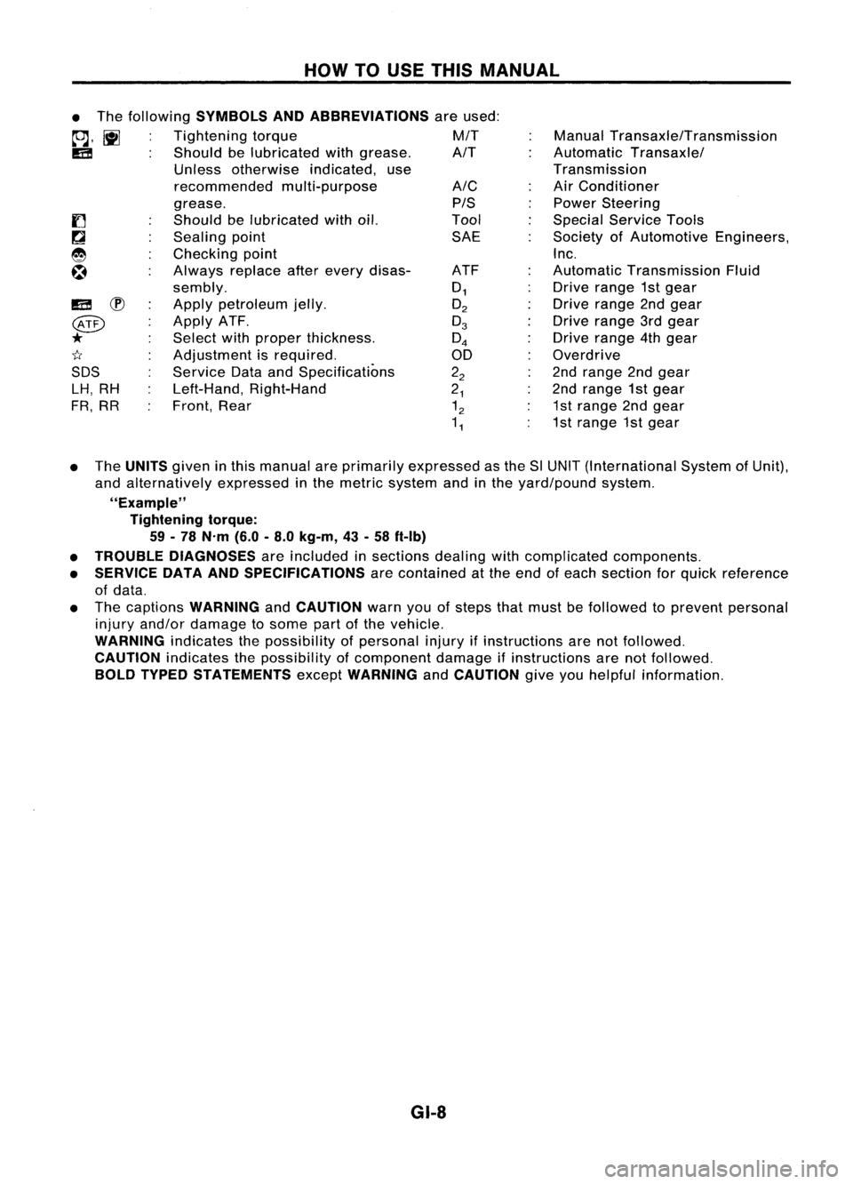
HOWTOUSE THIS MANUAL
ManualTransaxle/Transmission
Automatic Transaxle/
Transmission
Air Conditioner
Power Steering
Special Service Tools
Society ofAutomotive Engineers,
Inc.
Automatic Transmission Fluid
Drive range 1stgear
Drive range 2ndgear
Drive range 3rdgear
Drive range 4thgear
Overdrive
2nd range 2ndgear
2nd range 1stgear
1st range 2ndgear
1st range 1stgear
A/C
PIS
Tool SAE
ATF
0
1
O
2
0
3
0
4
00
2
2
2
1
1
2
1
1
•
The following
SYMBOLS ANDABBREVIATIONS
areused:
to;J,
l\tI
Tightening torque M/T
IE!
Shouldbelubricated withgrease. A/T
Unless otherwise indicated,use
recommended multi-purpose
grease.
Should belubricated withoil.
Sealing point
Checking point
Always replaceafterevery disas-
sembly.
Apply petroleum jelly.
Apply ATF.
Select withproper thickness.
Adjustment isrequired.
Service DataandSpecifications
Left-Hand, Right-Hand
Front, Rear
IE!
~
@
*
1I
SDS LH, RH
FR, RR
• The
UNITS
giveninthis manual areprimarily expressed asthe SlUNIT (International SystemofUnit),
and alternatively expressedinthe metric system andinthe yard/pound system.
"Example" Tightening torque:
59 -78 N'm (6.0-8.0 kg-m, 43-58 ft-Ib)
• TROUBLE DIAGNOSES
areincluded insections dealingwithcomplicated components.
• SERVICE DATAANDSPECIFICATIONS
arecontained atthe end ofeach section forquick reference
of data.
• The captions
WARNING
and
CAUTION
warnyouofsteps thatmust befollowed toprevent personal
injury and/or damage tosome partofthe vehicle.
WARNING
indicatesthepossibility ofpersonal injuryifinstructions arenotfollowed.
CAUTION
indicatesthepossibility ofcomponent damageifinstructions arenotfollowed.
BOLD TYPED STATEMENTS
except
WARNING
and
CAUTION
giveyouhelpful information.
GI-8
Page 1371 of 1701
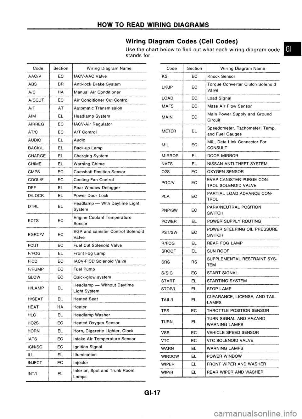
HOWTOREAD WIRING DIAGRAMS
Wiring Diagram Codes(CellCodes)
Use thechart below to'find outwhat each wiring diagram code•
stands for,
Code Section WiringDiagram Name
AACIV ECIACV-AAC
Valve
ABS BR
Anti-lock BrakeSystem
A/C HAManualAirConditioner
A/CCUT ECAir
Conditioner CutControl
A/T ATAutomatic Transmission
AIM ELHeadlamp System
AIRREG ECIACV-Air Regulator
AT/C ECA/TControl
AUDIO ELAudio
BACK/L ELBack-up Lamp
CHARGE ELCharging System
CHIME ELWarning Chime
CMPS EC
Camshaft PositionSensor
COOllF ECCooling
FanControl
DEF ELRearWindow Defogger
D/LOCK ELPowerDoorLock
DTRL ELHeadlamp
-With Daytime Light
System
ECTS ECEngine
Coolant Temperature
Sensor
EGR andcanister ControlSolenoid
EGRCIV EC
Valve
FCUT ECFuel
CutSolenoid Valve
F/FOG ELFront
FogLamp
FICO ECIACV-FICD
SolenoidValve
F/PUMP ECFuel
Pump
GLOW ECQuick-glow
system
H/LAMP ELHeadlamp
-Without Daytime
Light System
H/SEAT ELHeated
Seat
HEAT HA
Heater
HLC ELHeadlamp
Washer
H02S ECHeated
Oxygen Sensor
HORN ELHorn,
Cigarette Lighter,Clock
IATS ECIntake
AirTemperature Sensor
IGN/SG ECIgnition
Signal
ILL ELIllumination
INJECT ECInjector
INT/L ELInterior,
SpotandTrunk Room
Lamps Code
Section WiringDiagram Name
KS ECKnock
Sensor
LKUP ECTorque
Converter ClutchSolenoid
Valve
LOAD ECLoadSignal
MAFS ECMass
AirFlow Sensor
MAIN ECMain
Power Supply andGround
Circuit
METER ELSpeedometer,
Tachometer,Temp.
and Fuel Gauges
MIL ECMIL,
Data LinkConnector For
CONSULT
MIRROR ELDOOR
MIRROR
NATS ELNISSAN
ANTI-THEFT SYSTEM
02S ECOXYGEN
SENSOR
EC EVAP
CANISTER PURGECON-
PGCIV TROLSOLENOID VALVE
PLA ECPARTIAL
LOADADVANCE CON-
TROL
EC PARK/NEUTRAL
POSITION
PNP/SW SWITCH
POWER ELPOWER
SUPPLY ROUTING
POWER STEERING OILPRESSURE
PST/SW EC
SWITCH
R/FOG ELREAR
FOGLAMP
SROOF ELSUN
ROOF
SUPPLEMENTAL RESTRAINTSYS-
SRS RS
TEM
S/SIG ECST
ART SIGNAL
START ELSTARTING
SYSTEM
STOP/L ELSTOP
LAMP
TAllIL ELCLEARANCE,
LICENSE,ANDTAIL
LAMPS
TPS ECTHROTTLE
POSITIONSENSOR
TURN SIGNAL ANDHAZARD
TURN EL
WARNING LAMPS
VSS ECVEHICLE
SPEEDSENSOR
VTC ECVTC
SOLENOID VALVE
WARN ELWARNING
LAMPS
WINDOW ELPOWER
WINDOW
WIPER ELFRONT
WIPERANDWASHER
WIP/R ELREAR
WIPER ANDWASHER
GI-17
Page 1372 of 1701
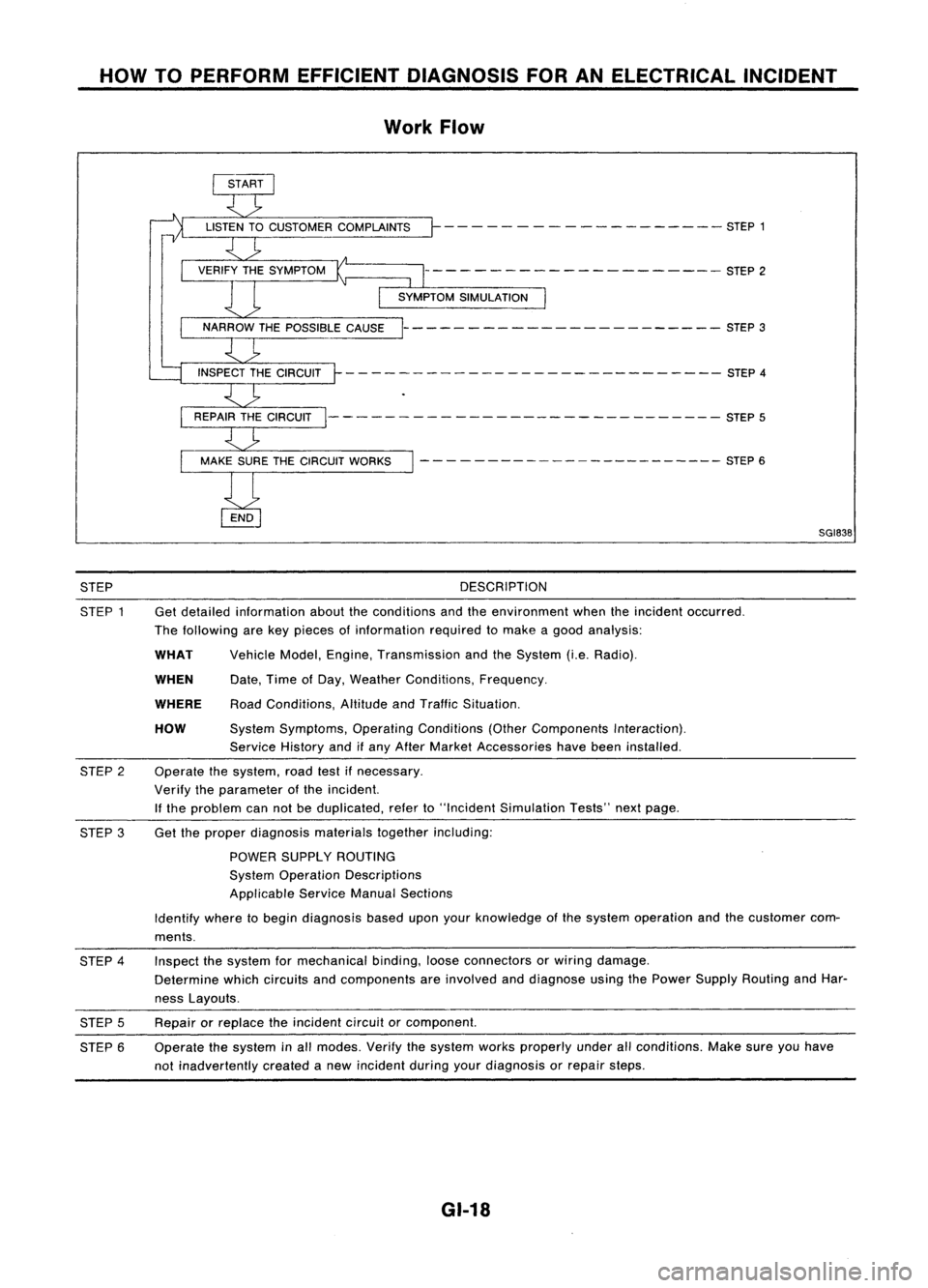
HOWTOPERFORM EFFICIENT DIAGNOSIS FORANELECTRICAL INCIDENT
Work Flow
- - - -- - -- ------ -- - -- STEP 1
--------------------- STEP2
----------------------- STEP3
- - -- ---- - --- - -- --- --- - - --- -- STEP 4
--------- -------------------- STEP5
- - - - ---- -- -- -- -- -- --- --- STEP 6
SGI838
STEP
STEP 1 DESCRIPTION
Get detailed information abouttheconditions andtheenvironment whentheincident occurred.
The following arekey pieces ofinformation requiredtomake agood analysis:
HOW
WHEN
WHAT
WHERE
Vehicle
Model,Engine, Transmission andtheSystem (i.e.Radio).
Date, TimeofDay, Weather Conditions, Frequency.
Road Conditions, AltitudeandTraffic Situation.
System Symptoms, OperatingConditions (OtherComponents Interaction).
Service Historyandifany After Market Accessories havebeen installed.
Operate thesystem, roadtestifnecessary.
Verify theparameter ofthe incident.
If the problem cannotbeduplicated, referto"Incident Simulation Tests"nextpage.
STEP
2
STEP 3Get
theproper diagnosis materialstogetherincluding:
POWER SUPPLY ROUTING
System Operation Descriptions
Applicable ServiceManualSections
Identify wheretobegin diagnosis baseduponyourknowledge ofthe system operation andthecustomer com-
ments.
STEP 4
STEP 5
STEP 6 Inspect
thesystem formechanical binding,looseconnectors orwiring damage.
Determine whichcircuits andcomponents areinvolved anddiagnose usingthePower Supply Routing andHar-
ness Layouts.
Repair orreplace theincident circuitorcomponent.
Operate thesystem inall modes. Verifythesystem worksproperly underallconditions. Makesureyouhave
not inadvertently createdanew incident duringyourdiagnosis orrepair steps.
GI-18
Page 1389 of 1701
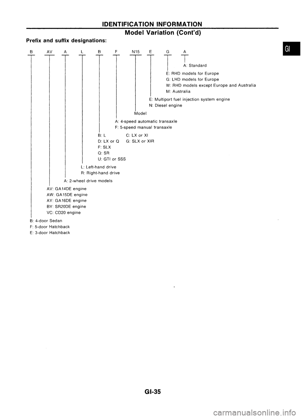
IDENTIFICATIONINFORMATION
Model Variation (Cont'd)
Prefix andsuffix designations:
B
AV
A
L
B
FN15
E
G
T
A
T
A: Standard
•
Model E:
RHO models forEurope
G: LHD models forEurope
W: RHO models exceptEurope andAustralia
M: Australia
E: Multiport fuelinjection systemengine
N: Diesel engine
A: 4-speed automatic transaxle
F: 5-speed manualtransaxle
B: L
0: LX or
Q
F: SLX
Q:SR
U: GTI orSSS
L: Left-hand drive
R: Right-hand drive
A: 2-wheel drivemodels
AV: GA14DE engine
AW: GA15DE engine
AY: GA16DE engine
BY: SR20DE engine
VC: CD20 engine
B: 4-door Sedan
F: 5-door Hatchback
E: 3-door Hatchback C:
LX orXI
G: SLX orXIR
GI-35
Page 1392 of 1701
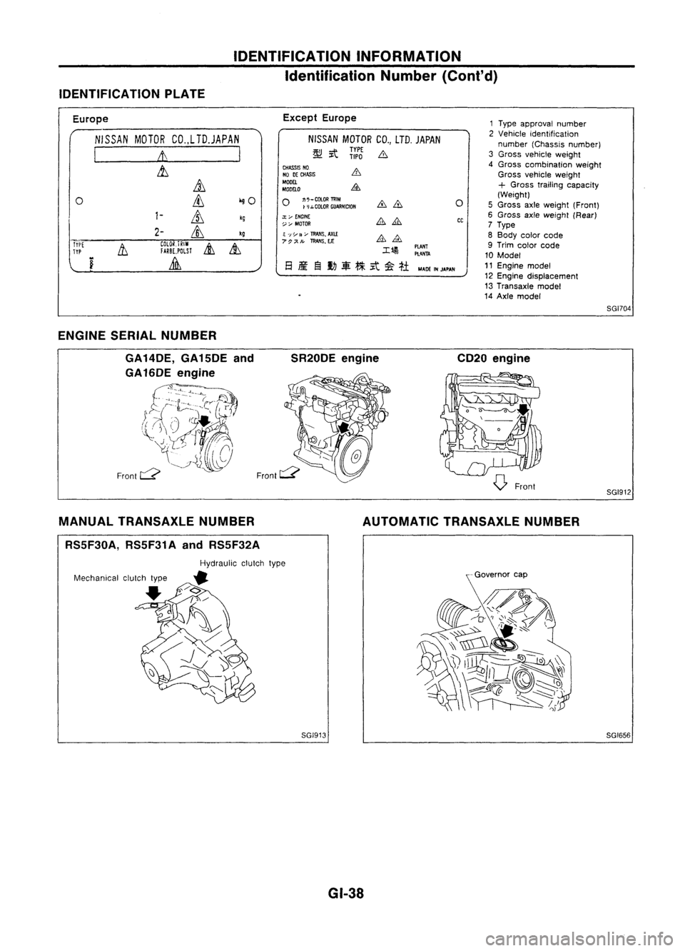
IDENTIFICATIONINFORMATION
Identification Number(Cont'd)
IDENTIFICATION PLATE
Europe
NISSAN MOTORCO.,LTD.JAPAN
I
It
I
&,
it
0
ill
iliO
1-
ill
kg
2-
&,
kg
Tri'[
11
COlOR.iRIM
&
&,
TYP
fARBE,POLSl
i
Lilli
Except
Europe
NISSAN MOTORCO.,LTD. JAPAN
~ it
ii:J
b
CHASS~ NO
NO DECHASIS
MODEL
MDDELO
o
~;::~:~~NlctDN
.:t;..-
ENGINE
~:,... MOTOR
~ ';;Y
3;..-
TRANS~
AXl.£
7P;;<'.
ll!AIIS.EJt:
M4DEINJAPAN
o
CC
1
Type approval number
2 Vehicle identification
number (Chassis number)
3 Gross vehicle weight
4 Gross combination weight
Gross vehicle weight
+
Gross trailing capacity
(Weight)
5 Gross axleweight (Front)
6 Gross axleweight (Rear)
7 Type
8 Body colorcode
9 Trim color code
10 Model
11 Engine model
12 Engine displacement
13 Transaxle model
14 Axle model
SGI704
ENGINE SERIALNUMBER
GA 14DE, GA15DE and
GA16DE engine
£~b-=~~rrf~)
(J~~~6
Front
c:::?
SR20DE
engine CD20engine
SGI912
MANUAL TRANSAXLE NUMBER
RS5F30A, RS5F31AandRS5F32A AUTOMATIC
TRANSAXLE NUMBER
SGI913 GI-38 SGI656
Page 1397 of 1701
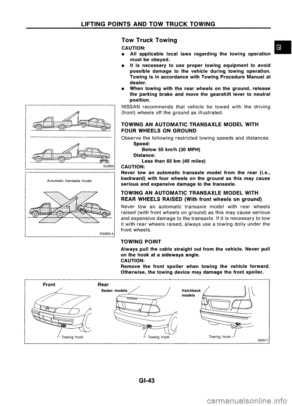
LIFTINGPOINTSANDTOW TRUCK TOWING
~ SGI80S
Automatic transaxlemodel
SG1806-A Tow
Truck Towing •
CAUTION: • All applicable locallawsregarding thetowing operation
must beobeyed.
• Itis necessary touse proper towing equipment toavoid
possible damagetothe vehicle duringtowing operation.
Towing isinaccordance withTowing Procedure Manualat
dealer.
• When towing withtherear wheels onthe ground, release
the parking brakeandmove thegearshift levertoneutral
position.
NISSAN recommends thatvehicle betowed withthedriving
(front) wheels offthe ground asillustrated.
TOWING ANAUTOMATIC TRANSAXLEMODELWITH
FOUR WHEELS ONGROUND
Observe thefollowing restricted towingspeeds anddistances.
Speed: Below 50km/h (30MPH)
Distance: Less than65km (40 miles)
CAUTION: Never towanautomatic transaxlemodelfromtherear
(i.e.,
backward) withfourwheels onthe ground asthis may cause
serious andexpensive damagetothe transaxle.
TOWING ANAUTOMATIC TRANSAXLEMODELWITH
REAR WHEELS RAISED(Withfrontwheels onground)
Never towanautomatic transaxlemodelwithrearwheels
raised (withfrontwheels onground) asthis may cause serious
and expensive damagetothe transaxle. Ifitis necessary totow
it with rearwheels raised,always useatowing dollyunder the
front wheels.
TOWING POINT
Always pullthecable straight outfrom thevehicle. Neverpull
on the hook atasideways angle.
CAUTION: Remove thefront spoiler whentowing thevehicle forward.
Otherwise, thetowing devicemaydamage thefront spoiler.
Front Rear
Sedan models
GI-43
Hatchback
models
Towinghook
SGI911
Page 1491 of 1701
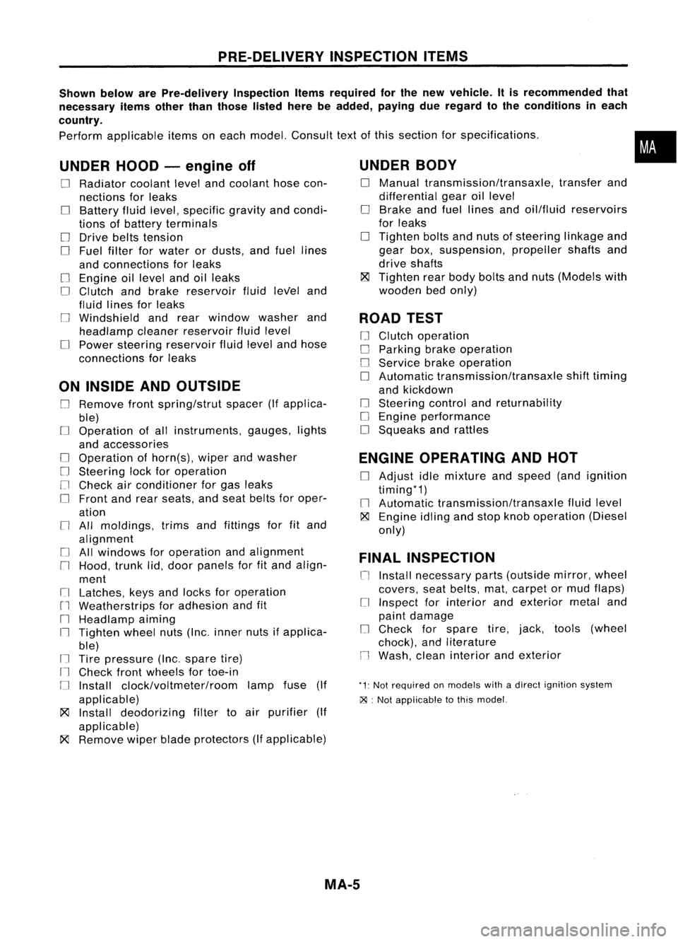
PRE-DELIVERYINSPECTIONITEMS
Shown belowarePre-delivery InspectionItemsrequired forthe new vehicle. Itis recommended that
necessary itemsotherthanthose listedherebeadded, payingdueregard tothe conditions ineach
country.
Perform applicable itemsoneach model. Consult textofthis section forspecifications .
UNDER HOOD-engine off
o
Radiator coolantlevelandcoolant hosecon-
nections forleaks
o
Battery fluidlevel, specific gravityandcondi-
tions ofbattery terminals
o
Drive beltstension
D
Fuel filter forwater ordusts, andfuel lines
and connections forleaks
[] Engine oillevel andoilleaks
D
Clutch andbrake reservoir fluidlevel and
fluid lines forleaks
o
Windshield andrear window washerand
headlamp cleanerreservoir fluidlevel
D
Power steering reservoir fluidlevel andhose
connections forleaks
ON INSIDE ANDOUTSIDE
D
Remove frontspring/strut spacer(Ifapplica-
ble)
D
Operation ofall instruments, gauges,lights
and accessories
o
Operation ofhorn(s), wiperandwasher
[] Steering lockforoperation
[] Check airconditioner forgas leaks
o
Front andrear seats, andseat belts foroper-
ation
n
All moldings, trimsandfittings forfitand
alignment
[J
Allwindows foroperation andalignment
n
Hood, trunklid,door panels forfitand align-
ment
[1
Latches, keysandlocks foroperation
rl
Weatherstrips foradhesion andfit
[l
Headlamp aiming
I~ Tighten wheelnuts(Inc. inner nutsifapplica-
ble)
IJ Tire pressure (Inc.spare tire)
Il
Check frontwheels fortoe-in
IJ Install clock/voltmeter/room lampfuse(If
applicable)
~ Install deodorizing filtertoair purifier (If
applicable)
~ Remove wiperbladeprotectors (Ifapplicable)
UNDER
BODY
o
Manual transmission/transaxle, transferand
differential gearoillevel
D
Brake andfuel lines andoil/fluid reservoirs
for leaks
D
Tighten boltsandnuts ofsteering linkageand
gear box,suspension, propellershaftsand
drive shafts
~ Tighten rearbody boltsandnuts (Models with
wooden bedonly)
ROAD TEST
D
Clutch operation
D
Parking brakeoperation
[J
Service brakeoperation
D
Automatic transmission/transaxle shifttiming
and kickdown
[] Steering controlandreturnability
o
Engine performance
D
Squeaks andrattles
ENGINE OPERATING ANDHOT
D
Adjust idlemixture andspeed (andignition
timing*1)
n
Automatic transmission/transaxle fluidlevel
~ Engine idlingandstop knob operation (Diesel
only)
FINAL INSPECTION
n
Install necessary parts(outside mirror,wheel
covers, seatbelts, mat,carpet ormud flaps)
[1
Inspect forinterior andexterior metaland
paint damage
[] Check forspare tire,jack, tools (wheel
chock), andliterature
n
Wash, cleaninterior andexterior
"1: Not required onmodels withadirect ignition system
~ :Not appiicable tothis model.
•
MA-5
Page 1494 of 1701
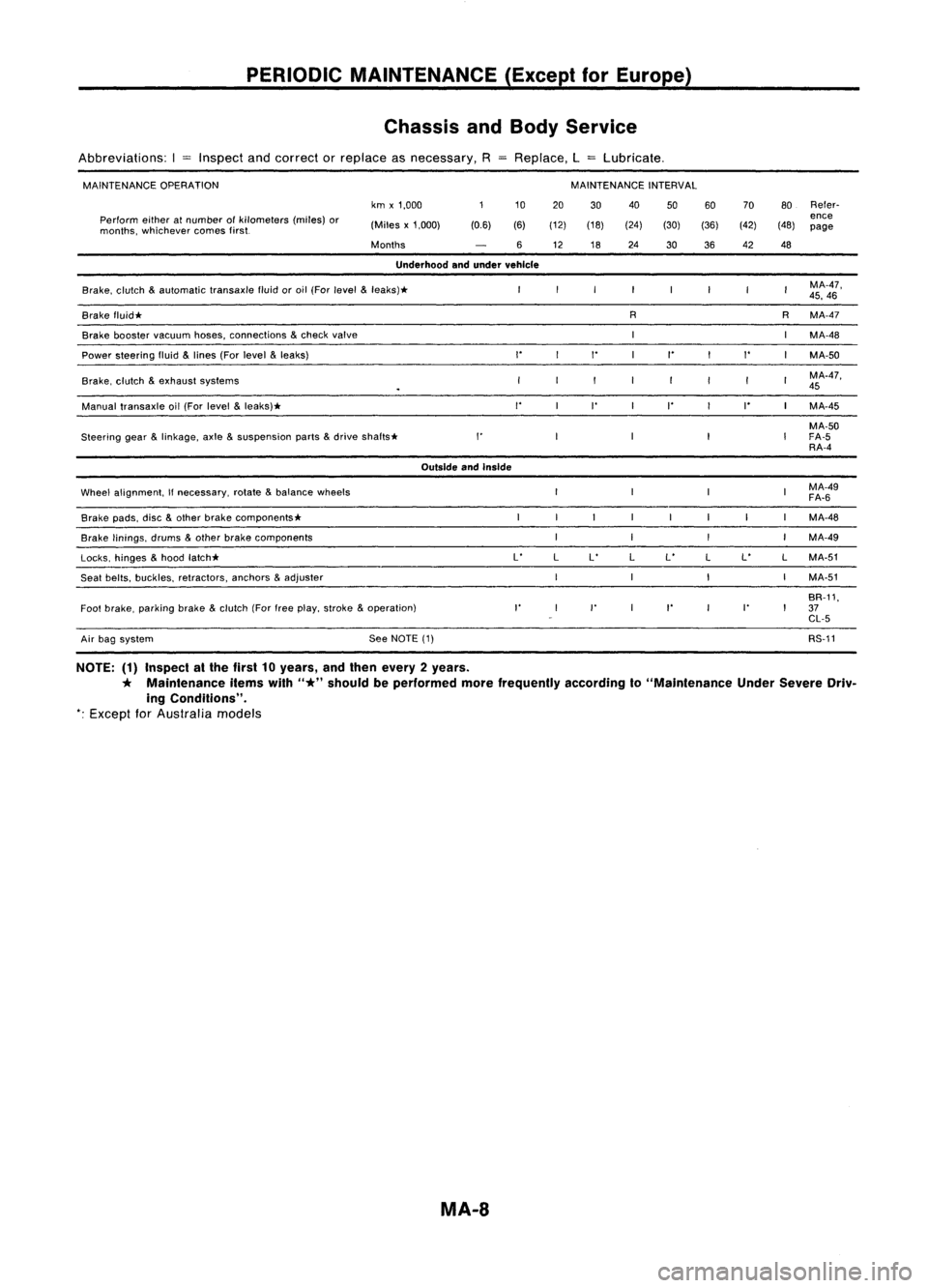
PERIODICMAINTENANCE (ExceptforEurope)
Chassis andBody Service
Abbreviations: I
=
Inspect andcorrect orreplace asnecessary, RReplace, L
=
Lubricate.
MAINTENANCE OPERATION MAINTENANCE
INTERVAL
km x1,000 10
20 30 40
5060 70
80Refer-
Perform eitheratnumber ofkilometers (miles)or
ence
months, whichever comesfirst. (Miles
x1,000) (0.6)(6)(12) (18) (24)(30)(36) (42)(48)
page
Months 612 1824
3036 42
48
Underhood andunder vehicle
Brake, clutch
&
automatic transaxlefluidoroil (For
level
&
leaks)* MA-47,
45, 46
Brake fluid* R
RMA-47
Brake booster
vacuum
hoses,connections
&
check
valve
MA-48
Power steering fluid
&
lines (For
level
&
leaks)
""
I'
"
MA-50
Brake, clutch
&
exhaust systems MA-47,
45
Manual transaxle oil(For level
&
leaks)*
"
I'
I' I'
MA-45
MA-50
Steering gear
&
linkage, axle
&
suspension parts
&
drive
shafts* I'
FA-5
RA-4
Outside andInside
Wheel alignment,
If
necessary, rotate
&
balance wheels MA-49
FA-6
Brake pads,disc
&
other brake components* MA-48
Brake linings, drums
&
other brake components MA-49
Locks, hinges
&
hood latch* L'
LL' LL'
LL'
LMA-51
Seat belts, buckles, retractors, anchors
&
adjuster MA-51
BR-11,
Foot brake, parking brake
&
clutch (Forfreeplay, stroke
&
operation)
I'
I'
I'
I'
37
CL-5
Air bag system See
NOTE (1) RS-11
NOTE: (1)Inspect atthe first 10years, andthen every 2years.
*
Maintenance itemswith
"*"
should beperformed morefrequently accordingto"Maintenance UnderSevere Driv-
ing Conditions".
*:
Except
for
Australia models
MA-8