1995 ACURA TL ECO mode
[x] Cancel search: ECO modePage 514 of 1771
ABS Functio n Tes t
1. Rais e th e ca r of f th e ground , an d suppor t i t wit h safet y
stands .
2. Chec k tha t ther e is n o brak e drag .
3 . Tur n th e ignitio n switc h O N (II) , an d confir m tha t th e
AB S indicato r ligh t come s on .
• I f th e AB S indicato r ligh t doe s no t com e on , follo w
th e troubleshootin g o n pag e 19-16 .
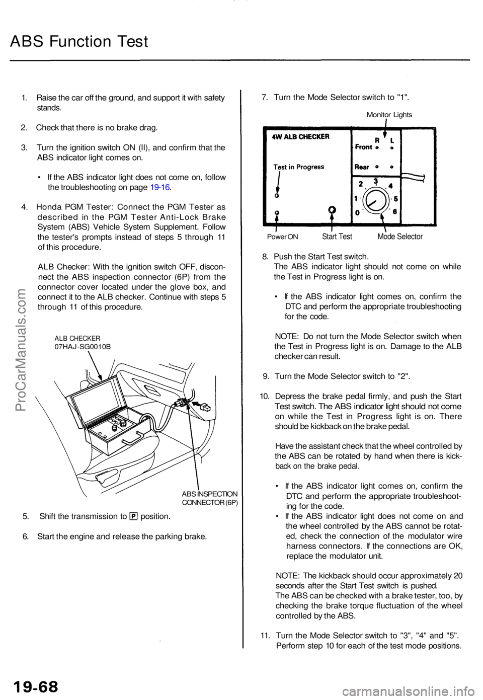
4 . Hond a PG M Tester : Connec t th e PG M Teste r a s
describe d i n th e PG M Teste r Anti-Loc k Brak e
Syste m (ABS ) Vehicl e Syste m Supplement . Follo w
th e tester' s prompt s instea d o f step s 5 throug h 1 1
o f thi s procedure .
AL B Checker : Wit h th e ignitio n switc h OFF , discon -
nec t th e AB S inspectio n connecto r (6P ) fro m th e
connecto r cove r locate d unde r th e glov e box , an d
connec t i t t o th e AL B checker . Continu e wit h step s 5
throug h 1 1 o f thi s procedure .
ALB CHECKE R07HAJ-SG0010 B
ABS
INSPECTIO NCONNECTO R (6P )
5. Shif t th e transmissio n t o position .
6 . Star t th e engin e an d releas e th e parkin g brake . 7
. Tur n th e Mod e Selecto r switc h t o "1" .
Monito r Light s
Powe r O NStar t Tes t
8. Pus h th e Star t Tes t switch .
Th e AB S indicato r ligh t shoul d no t com e o n whil e
th e Tes t i n Progres s ligh t i s on .
• I f th e AB S indicato r ligh t come s on , confir m th e
DT C an d perfor m th e appropriat e troubleshootin g
fo r th e code .
NOTE : D o no t tur n th e Mod e Selecto r switc h whe n
th e Tes t i n Progres s ligh t i s on . Damag e to th e AL B
checke r ca n result .
9 . Tur n th e Mod e Selecto r switc h t o "2" .
10 . Depres s th e brak e peda l firmly , an d pus h th e Star t
Test switch . Th e AB S indicato r ligh t shoul d no t com e
on whil e th e Tes t i n Progres s ligh t i s on . Ther e
shoul d b e kickbac k o n th e brak e pedal .
Hav e th e assistan t chec k tha t th e whee l controlle d b y
th e AB S ca n b e rotate d b y han d whe n ther e is kick -
back o n th e brak e pedal .
• I f th e AB S indicato r ligh t come s on , confir m th e
DT C an d perfor m th e appropriat e troubleshoot -
ing fo r th e code .
• I f th e AB S indicato r ligh t doe s no t com e o n an d
th e whee l controlle d b y th e AB S canno t b e rotat -
ed , chec k th e connectio n o f th e modulato r wir e
harnes s connectors . I f th e connection s ar e OK ,
replac e th e modulato r unit .
NOTE : Th e kickbac k shoul d occu r approximatel y 2 0
second s afte r th e Star t Tes t switc h i s pushed .
Th e AB S can be checke d wit h a brak e tester , too , b y
checkin g th e brak e torqu e fluctuatio n o f th e whee l
controlle d b y th e ABS .
11 . Tur n th e Mod e Selecto r switc h t o "3" , "4 " an d "5" .
Perfor m ste p 1 0 fo r eac h o f th e tes t mod e positions .
Mode Selecto r
ProCarManuals.com
Page 516 of 1771
Master Cylinde r
Pushrod Clearanc e Adjustmen t
NOTE: Maste r cylinde r pushrod-t o pisto n clearanc e
mus t b e checke d an d adjustment s made , i f necessary ,
befor e installin g maste r cylinder .
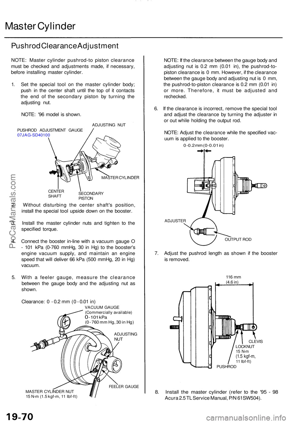
1 . Se t th e specia l too l o n th e maste r cylinde r body ;
pus h i n th e cente r shaf t unti l th e to p o f i t contact s
th e en d o f th e secondar y pisto n b y turnin g th e
adjustin g nut .
NOTE : '9 6 mode l i s shown .
PUSHRO D ADJUSTMEN T GAUG E
07JAG-SD4010 0 ADJUSTIN
G NU T
MASTE R CYLINDE R
CENTERSHAFTSECONDAR YPISTON
2. Withou t disturbin g th e cente r shaft' s position ,
instal l th e specia l too l upsid e dow n o n th e booster .
3 . Instal l th e maste r cylinde r nut s an d tighte n t o th e
specifie d torque .
4 . Connec t th e booste r in-lin e wit h a vacuu m gaug e O
- 10 1 kP a (0-76 0 mmHg , 3 0 in Hg ) t o th e booster' s
engin e vacuu m supply , an d maintai n a n engin e
spee d tha t wil l delive r 6 6 kP a (50 0 mmHg , 2 0 in Hg )
vacuum .
5 . Wit h a feele r gauge , measur e th e clearanc e
betwee n th e gaug e bod y an d th e adjustin g nu t a s
shown .
Clearance : 0 - 0.2 m m (0 - 0.0 1 in )
VACUU M GAUG E
(Commerciall y available )
0 - 101 kP a(0 - 76 0 m m Hg , 3 0 in Hg )
ADJUSTIN GNUT
FEELE R GAUG EMASTE R CYLINDE R NU T
1 5 N- m (1. 5 kgf-m , 1 1 Ibf-ft )
NOTE : I f th e clearanc e betwee n th e gaug e bod y an d
adjustin g nu t i s 0. 2 m m (0.0 1 in) , th e pushrod-to -
pisto n clearanc e is 0 mm . However , i f th e clearanc e
betwee n th e gaug e bod y an d adjustin g nu t i s 0 mm ,
th e pushrod-to-pisto n clearanc e is 0. 2 m m (0.0 1 in )
o r more . Therefore , i t mus t b e adjuste d an d
rechecked .
6. I f th e clearanc e is incorrect , remov e th e specia l too l
an d adjus t th e clearanc e b y turnin g th e adjuste r i n
o r ou t whil e holdin g th e outpu t rod .
NOTE : Adjus t th e clearanc e whil e th e specifie d vac -
uu m is applie d t o th e booster .
0 -0. 2 m m (0-0.0 1 in )
ADJUSTE R
OUTPUT RO D
7. Adjus t th e pushro d lengt h a s show n i f th e booste r
i s removed .
116 m m(4.6 in)
8. Instal l th e maste r cylinde r (refe r t o th e '9 5 - 9 8
Acur a 2. 5 T L Servic e Manual , P/ N 61SW504) .
LOCKNUT15 N- m(1.5 kgf-m ,11 Ibf-ft )
CLEVI S
PUSHRO D
ProCarManuals.com
Page 524 of 1771
Diagnostic Troubl e Cod e (DTC )
Diagnosti c Troubl e Cod e (DTC ) Indicatio n (SC S Mode )
NOTE: Thi s operatio n ca n als o b e don e wit h th e Hond a PG M Tester .
1 . Connec t th e SC S servic e connecto r t o th e servic e chec k connecto r (2P ) unde r th e glov e box .
2 . Tur n th e ignitio n switc h O N (II ) withou t brak e peda l depressed .
NOTE : I f th e brak e peda l i s depresse d whe n turnin g th e ignitio n switc h O N (II) , th e syste m shift s t o ME S mode .
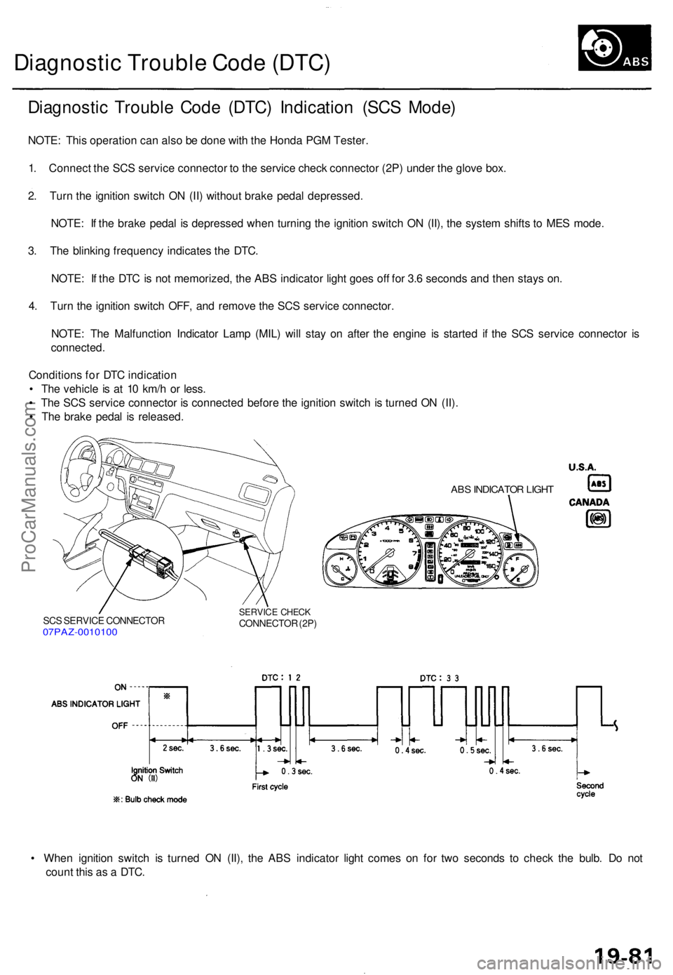
3 . Th e blinkin g frequenc y indicate s th e DTC .
NOTE : I f th e DT C is no t memorized , th e AB S indicato r ligh t goe s of f fo r 3. 6 second s an d the n stay s on .
4 . Tur n th e ignitio n switc h OFF , an d remov e th e SC S servic e connector .
NOTE : Th e Malfunctio n Indicato r Lam p (MIL ) wil l sta y o n afte r th e engin e i s starte d i f th e SC S servic e connecto r i s
connected .
Condition s fo r DT C indicatio n
• Th e vehicl e is a t 1 0 km/ h o r less .
• Th e SC S servic e connecto r i s connecte d befor e th e ignitio n switc h i s turne d O N (II) .
• Th e brak e peda l i s released .
SCS SERVIC E CONNECTO R07PAZ-001010 0
SERVICE CHEC KCONNECTO R (2P )
ABS INDICATO R LIGH T
• Whe n ignitio n switc h i s turne d O N (II) , th e AB S indicato r ligh t come s o n fo r tw o second s t o chec k th e bulb . D o no t
coun t thi s a s a DTC .
ProCarManuals.com
Page 525 of 1771
Diagnostic Troubl e Cod e (DTC )
DTC Erasur e (ME S Mode )
NOTE: Thi s operatio n ca n als o b e don e wit h th e Hond a PG M Tester .
1 . Connec t th e SC S servic e connecto r t o th e servic e chec k connecto r (2P ) unde r th e glov e box .
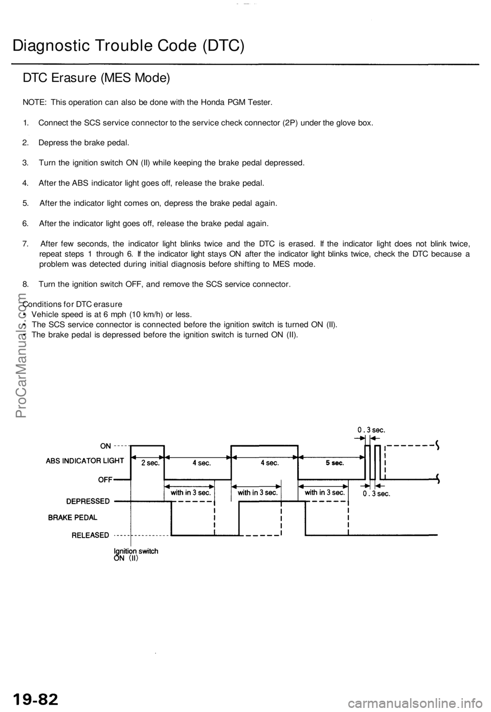
2 . Depres s th e brak e pedal .
3 . Tur n th e ignitio n switc h O N (II ) whil e keepin g th e brak e peda l depressed .
4 . Afte r th e AB S indicator light goe s off , releas e th e brak e pedal .
5 . Afte r th e indicato r ligh t come s on , depres s th e brak e peda l again .
6 . Afte r th e indicato r ligh t goe s off , releas e th e brak e peda l again .
7 . Afte r fe w seconds , th e indicato r ligh t blink s twic e an d th e DT C is erased . I f th e indicato r ligh t doe s no t blin k twice ,
repea t step s 1 throug h 6 . I f th e indicato r ligh t stay s O N afte r th e indicato r ligh t blink s twice , chec k th e DT C becaus e a
proble m wa s detecte d durin g initia l diagnosi s befor e shiftin g t o ME S mode .
8 . Tur n th e ignitio n switc h OFF , an d remov e th e SC S servic e connector .
Condition s fo r DT C erasur e
• Vehicl e spee d i s a t 6 mp h (1 0 km/h ) o r less .
• Th e SC S servic e connecto r i s connecte d befor e th e ignitio n switc h i s turne d O N (II) .
• Th e brak e peda l i s depresse d befor e th e ignitio n switc h i s turne d O N (II) .
ProCarManuals.com
Page 539 of 1771
Electronic Component s
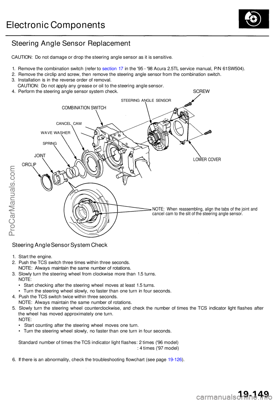
Steering Angl e Senso r Replacemen t
CAUTION: D o no t damag e o r dro p th e steerin g angl e senso r a s it i s sensitive .
1 . Remov e th e combinatio n switc h (refe r t o sectio n 1 7 in th e '9 5 - '9 8 Acur a 2.5T L servic e manual , P/ N 61SW504) .
2 . Remov e th e circli p an d screw , the n remov e th e steerin g angl e senso r fro m th e combinatio n switch .
3 . Installatio n i s i n th e revers e orde r o f removal .
CAUTION : D o no t appl y an y greas e o r oi l t o th e steerin g angl e sensor .
4 . Perfor m th e steerin g angl e senso r syste m check . SCRE W
STEERING ANGL E SENSO R
COMBINATIO N SWITC H
CANCE L CA M
WAV E WASHE R
SPRING
LOWER COVE R
NOTE: Whe n reassembling , alig n th e tab s o f th e join t an d
cance l ca m to th e sli t o f th e steerin g angl e sensor .
Steering Angl e Senso r Syste m Chec k
1. Star t th e engine .
2 . Pus h th e TC S switc h thre e time s withi n thre e seconds .
NOTE: Alway s maintai n th e sam e numbe r o f rotations .
3. Slowl y tur n th e steerin g whee l fro m clockwis e mor e tha n 1. 5 turns .
NOTE :
• Star t checkin g afte r th e steerin g whee l move s a t leas t 1. 5 turns .
• Tur n th e steerin g whee l slowly , n o faste r tha n on e tur n in fou r seconds .
4 . Pus h th e TC S switc h twic e withi n thre e seconds .
NOTE : Alway s maintai n th e sam e numbe r o f rotations .
5 . Slowl y tur n th e steerin g whee l counterclockwise , an d chec k th e numbe r o f time s th e TC S indicato r ligh t flashe s afte r
th e whee l ha s move d approximatel y on e turn .
NOTE :
• Star t countin g afte r th e steerin g whee l move s on e turn .
• Tur n th e steerin g whee l slowly , n o faste r tha n on e tur n i n fou r seconds .
Standar d numbe r o f time s th e TC S indicato r ligh t flashes : 2 time s ('9 6 model )
: 4 time s ('9 7 model )
6 . I f ther e is a n abnormality , chec k th e troubleshooting flowchart (se e pag e 19-126 ).
JOIN T
CIRCLI P
ProCarManuals.com
Page 570 of 1771
A/C System Service
Performance Test
The performance test will help determine if the air con-
ditioner system is operating within specifications.
Use only service equipment that is U.L.-listed and is cer-
tified to meet the requirements of SAE J2210 to remove
HFC-134a (R-134a) from the air conditioner system.
CAUTION: Exposure to air conditioner refrigerant and
lubricant vapor or mist can irritate eyes, nose and
throat. Avoid breathing the air conditioner refrigerant
and lubricant vapor or mist.
If accidental system discharge occurs, ventilate work
area before resuming service.
R-134a service equipment or vehicle air conditioner sys-
tems should not be pressure tested or leak tested with
compressed air.
Some mixtures of air and R-134a have been
shown to be combustible at elevated pressures and can
result in fire or explosion causing injury or property
damage. Never use compressed air to pressure test R-
134a service equipment or vehicle air conditioner sys-
tems.
Additional health and safety information may be obtained
from the refrigerant and lubricant manufacturers.
1.
2.
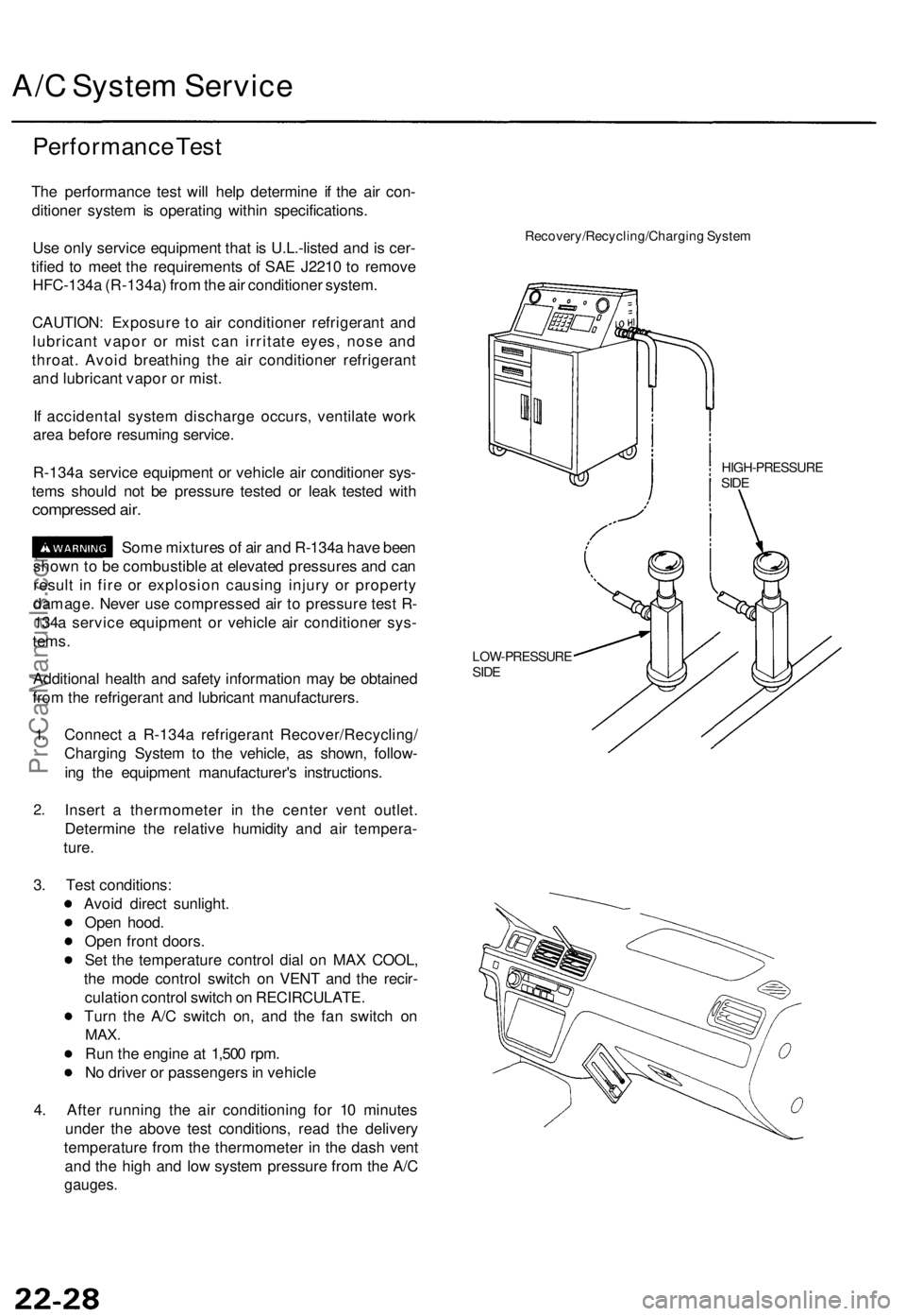
Connect a R-134a refrigerant Recover/Recycling/
Charging System to the vehicle, as shown, follow-
ing the equipment manufacturer's instructions.
Insert a thermometer in the center vent outlet.
Determine the relative humidity and air tempera-
ture.
Recovery/Recycling/Charging System
HIGH-PRESSURE
SIDE
LOW-PRESSURE
SIDE
3. Test conditions:
Avoid direct sunlight.
Open hood.
Open front doors.
Set the temperature control dial on MAX COOL,
the mode control switch on VENT and the recir-
culation control switch on RECIRCULATE.
Turn the A/C switch on, and the fan switch on
MAX.
Run the engine at 1,500 rpm.
No driver or passengers in vehicle
4. After running the air conditioning for 10 minutes
under the above test conditions, read the delivery
temperature from the thermometer in the dash vent
and the high and low system pressure from the A/C
gauges.ProCarManuals.com
Page 625 of 1771
Power Doo r Lock s Power Seat s
Remot e Transmitte r Replacemen t
Use th e followin g procedur e whe n replacin g on e o r bot h
remot e transmitters :
1 . Ope n th e driver' s door .
2 . Pres s an d hol d th e driver' s maste r doo r loc k switc h
u p in th e UNLOC K position .
3 . Quickl y inser t an d remov e th e ke y fro m th e ignitio n
switc h fiv e times , the n inser t th e ke y th e sixt h time ,
an d leav e i t i n th e ignitio n switch .
(Thi s routin e mus t b e don e withi n 1 0 seconds. )
All th e door s wil l loc k an d unloc k t o indicat e tha t
the contro l uni t i s i n th e progra m mode .
4 . Pres s eithe r butto n o n th e replacemen t transmitter .
Al l th e door s excep t th e driver' s doo r wil l loc k an d
unloc k t o indicat e tha t th e contro l uni t ha s accepte d
th e transmitte r int o it s memory . I f eithe r transmitte r
butto n i s presse d again , al l th e door s wil l loc k an d
unlock .
5. T o progra m a secon d transmitter , pres s eithe r but -
to n o n tha t transmitter . Th e door s shoul d loc k an d
unloc k a s describe d in ste p 4 .
6 . Releas e th e driver' s maste r doo r loc k switch .
7 . T o exi t th e progra m mode , clos e th e driver' s doo r
o r remov e th e ke y fro m th e ignitio n switch .
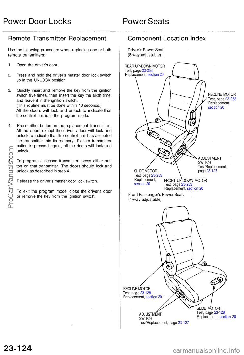
Componen t Locatio n Inde x
Driver' s Powe r Seat :
(8-wa y adjustable )
REAR UP-DOW N MOTO R
RECLINE MOTO R
SLID E MOTO R
ADJUSTMEN TSWITCH
Test/Replacement ,
pag e 23-12 7
FRON T UP-DOW N MOTO R
Front Passenger' s Powe r Seat :
(4-wa y adjustable )
RECLINE MOTO R
Test , pag e 23-12 8
Replacement , sectio n 2 0
ADJUSTMEN T
SWITC H
Test/Replacement , pag e 23-12 7 SLID
E MOTO R
Test , pag e 23-12 8
Replacement , sectio n 2 0
Test
, pag e 23- 253
Replacement , sectio n 2 0
Test
, pag e 23-253
Replacement ,
sectio n 2 0
Test
, pag e 23-253
Replacement , sectio n 2 0
Test, pag e 23-253
Replacement ,
sectio n 2 0
ProCarManuals.com
Page 646 of 1771
SRS Uni t Precaution s
Take extr a car e whe n paintin g o r doin g bod y wor k i n
th e are a belo w th e dashboard . Avoi d direc t exposur e
of th e SR S uni t o r wirin g t o hea t guns , welding , o r
sprayin g equipment .
Disconnec t th e airba g connector s befor e disconnect -
in g SR S harnes s connector s (se e pag e 24-11 ). O n a
'9 6 model , connec t th e shor t connecto r t o th e fron t
passenger' s airba g connector .
Afte r an y degre e o f fronta l bod y damage , o r afte r a
collisio n withou t airba g deployment , inspec t th e SR S
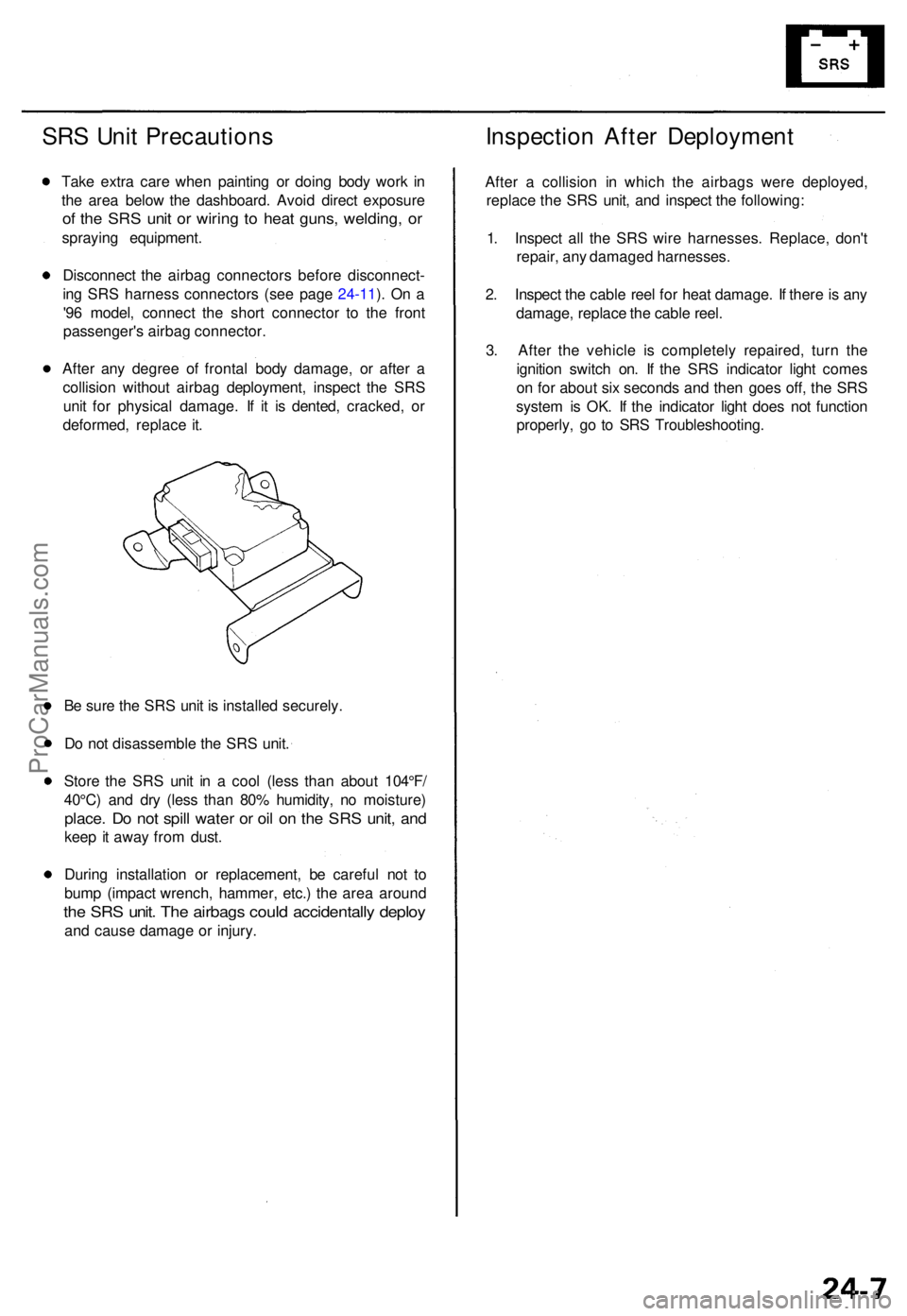
uni t fo r physica l damage . I f i t i s dented , cracked , o r
deformed , replac e it .
B e sur e th e SR S uni t i s installe d securely .
D o no t disassembl e th e SR S unit .
Stor e th e SR S uni t i n a coo l (les s tha n abou t 104°F /
40°C ) an d dr y (les s tha n 80 % humidity , n o moisture )
place. D o no t spil l wate r o r oi l o n th e SR S unit , an d
kee p it awa y fro m dust .
Durin g installatio n o r replacement , b e carefu l no t t o
bum p (impac t wrench , hammer , etc. ) th e are a aroun d
the SR S unit . Th e airbag s coul d accidentall y deplo y
and caus e damag e o r injury .
Inspectio n Afte r Deploymen t
After a collisio n i n whic h th e airbag s wer e deployed ,
replac e th e SR S unit , an d inspec t th e following :
1 . Inspec t al l th e SR S wir e harnesses . Replace , don' t
repair , an y damage d harnesses .
2 . Inspec t th e cabl e ree l fo r hea t damage . I f ther e is an y
damage , replac e th e cabl e reel .
3 . Afte r th e vehicl e i s completel y repaired , tur n th e
ignitio n switc h on . I f th e SR S indicato r ligh t come s
o n fo r abou t si x second s an d the n goe s off , th e SR S
syste m is OK . I f th e indicato r ligh t doe s no t functio n
properly , g o t o SR S Troubleshooting .
ProCarManuals.com