1995 ACURA TL ECO mode
[x] Cancel search: ECO modePage 159 of 1771
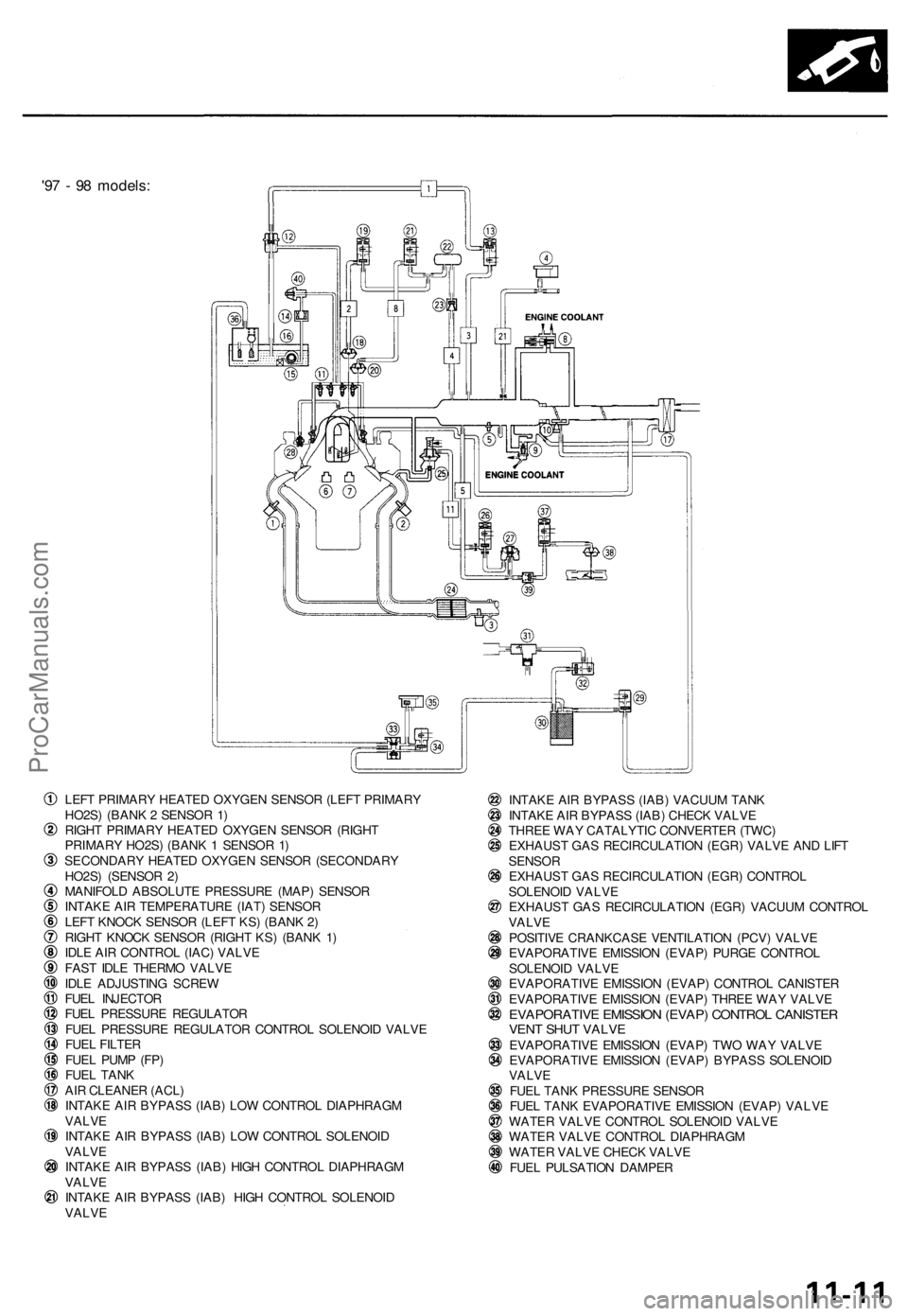
'97 - 98 models:
LEFT PRIMARY HEATED OXYGEN SENSOR (LEFT PRIMARY
HO2S) (BANK 2 SENSOR 1)
RIGHT PRIMARY HEATED OXYGEN SENSOR (RIGHT
PRIMARY HO2S) (BANK 1 SENSOR 1)
SECONDARY HEATED OXYGEN SENSOR (SECONDARY
HO2S) (SENSOR 2)
MANIFOLD ABSOLUTE PRESSURE (MAP) SENSOR
INTAKE AIR TEMPERATURE (IAT) SENSOR
LEFT KNOCK SENSOR (LEFT KS) (BANK 2)
RIGHT KNOCK SENSOR (RIGHT KS) (BANK 1)
IDLE AIR CONTROL (IAC) VALVE
FAST IDLE THERMO VALVE
IDLE ADJUSTING SCREW
FUEL INJECTOR
FUEL PRESSURE REGULATOR
FUEL PRESSURE REGULATOR CONTROL SOLENOID VALVE
FUEL FILTER
FUEL PUMP (FP)
FUEL TANK
AIR CLEANER (ACL)
INTAKE AIR BYPASS (IAB) LOW CONTROL DIAPHRAGM
VALVE
INTAKE AIR BYPASS (IAB) LOW CONTROL SOLENOID
VALVE
INTAKE AIR BYPASS (IAB) HIGH CONTROL DIAPHRAGM
VALVE
INTAKE AIR BYPASS (IAB) HIGH CONTROL SOLENOID
VALVE
INTAKE AIR BYPASS (IAB) VACUUM TANK
INTAKE AIR BYPASS (IAB) CHECK VALVE
THREE WAY CATALYTIC CONVERTER (TWC)
EXHAUST GAS RECIRCULATION (EGR) VALVE AND LIFT
SENSOR
EXHAUST GAS RECIRCULATION (EGR) CONTROL
SOLENOID VALVE
EXHAUST GAS RECIRCULATION (EGR) VACUUM CONTROL
VALVE
POSITIVE CRANKCASE VENTILATION (PCV) VALVE
EVAPORATIVE EMISSION (EVAP) PURGE CONTROL
SOLENOID VALVE
EVAPORATIVE EMISSION (EVAP) CONTROL CANISTER
EVAPORATIVE EMISSION (EVAP) THREE WAY VALVE
EVAPORATIVE EMISSION (EVAP) CONTROL CANISTER
VENT SHUT VALVE
EVAPORATIVE EMISSION (EVAP) TWO WAY VALVE
EVAPORATIVE EMISSION (EVAP) BYPASS SOLENOID
VALVE
FUEL TANK PRESSURE SENSOR
FUEL TANK EVAPORATIVE EMISSION (EVAP) VALVE
WATER VALVE CONTROL SOLENOID VALVE
WATER VALVE CONTROL DIAPHRAGM
WATER VALVE CHECK VALVE
FUEL PULSATION DAMPERProCarManuals.com
Page 195 of 1771
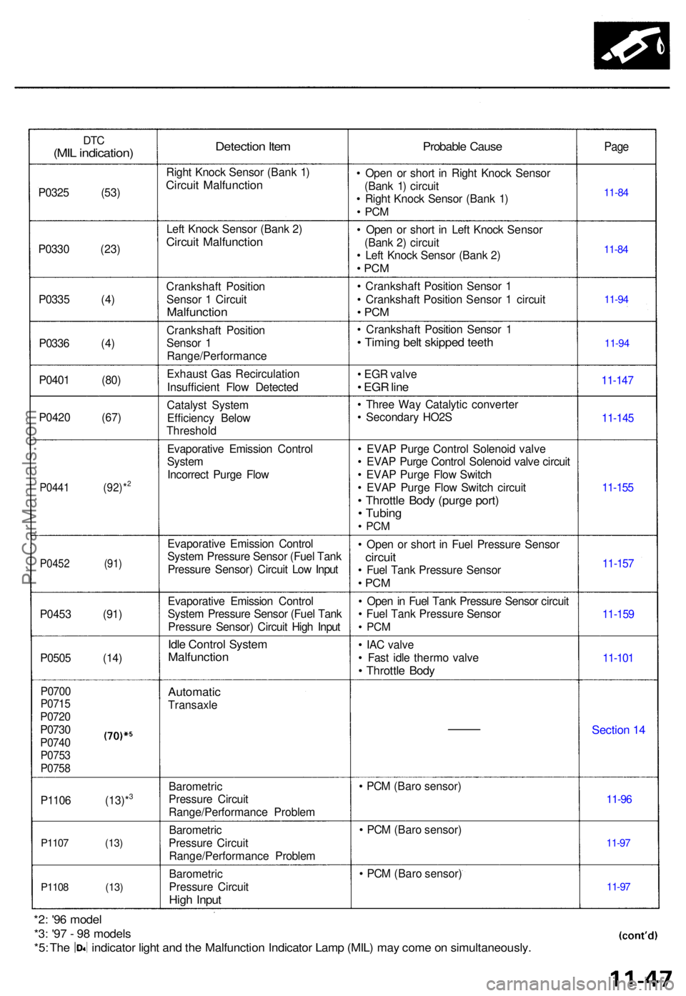
DTC(MI L indication )
P0325 (53 )
P033 0 (23 )
P033 5 (4 )
P033 6 (4 )
P040 1 (80 )
P042 0 (67 )
P0441 (92)*2
P045 2 (91 )
P0453 (91 )
P050 5 (14 )
P0700P0715
P072 0
P0730
P074 0P0753
P075 8
P1106 (13)*3
P110 7 (13 )
P110 8 (13 )
Detection Ite m
Righ t Knoc k Senso r (Ban k 1 )
Circui t Malfunctio n
Left Knoc k Senso r (Ban k 2 )
Circui t Malfunctio n
Crankshaft Positio n
Senso r 1 Circui t
Malfunctio n
Crankshaf t Positio n
Senso r 1
Range/Performanc e
Exhaust Gas Recirculatio n
Insufficien t Flo w Detecte d
Catalys t Syste m
Efficienc y Belo w
Threshol d
Evaporativ e Emissio n Contro l
Syste m
Incorrec t Purg e Flo w
Evaporativ e Emissio n Contro l
Syste m Pressur e Senso r (Fue l Tan k
Pressur e Sensor ) Circui t Lo w Inpu t
Evaporativ e Emissio n Contro l
Syste m Pressur e Senso r (Fue l Tan k
Pressur e Sensor ) Circui t Hig h Inpu t
Idle Contro l Syste mMalfunctio n
Automatic
Transaxle
Barometri c
Pressur e Circui t
Range/Performanc e Proble m
Barometri c
Pressur e Circui t
Range/Performanc e Proble m
Barometri c
Pressur e Circui t
High Inpu t
Probabl e Caus e
• Ope n o r shor t i n Righ t Knoc k Senso r
(Ban k 1 ) circui t
• Righ t Knoc k Senso r (Ban k 1 )
• PC M
• Ope n o r shor t i n Lef t Knoc k Senso r
(Ban k 2 ) circui t
• Lef t Knoc k Senso r (Ban k 2 )
• PC M
• Crankshaf t Positio n Senso r 1
• Crankshaf t Positio n Senso r 1 circui t
• PC M
• Crankshaf t Positio n Senso r 1
• Timin g bel t skippe d teet h
• EG R valv e
• EG R lin e
• Thre e Wa y Catalyti c converte r
• Secondar y HO2 S
• EVA P Purg e Contro l Solenoi d valv e
• EVA P Purg e Contro l Solenoi d valv e circui t
• EVA P Purg e Flo w Switc h
• EVA P Purg e Flo w Switc h circui t
• Throttl e Bod y (purg e port )• Tubin g
• PC M
• Ope n o r shor t i n Fue l Pressur e Senso r
circuit• Fue l Tan k Pressur e Senso r
• PC M
• Ope n in Fue l Tan k Pressur e Senso r circui t
• Fue l Tan k Pressur e Senso r
• PC M
• IA C valv e
• Fas t idl e therm o valv e
• Throttl e Bod y
• PC M (Bar o sensor )
• PC M (Bar o sensor )
• PC M (Bar o sensor )
Page
11-8 4
11-8 4
11-9 4
11-9 4
11-14 7
11-145
11-155
11-15 7
11-15 9
11-10 1
Sectio n 1 4
11-9 6
11-97
11-9 7
*2: '9 6 mode l
*3: '9 7 - 9 8 model s
*5: Th e indicato r ligh t an d th e Malfunctio n Indicato r Lam p (MIL ) ma y com e o n simultaneously .
ProCarManuals.com
Page 199 of 1771
PGM-FI Syste m
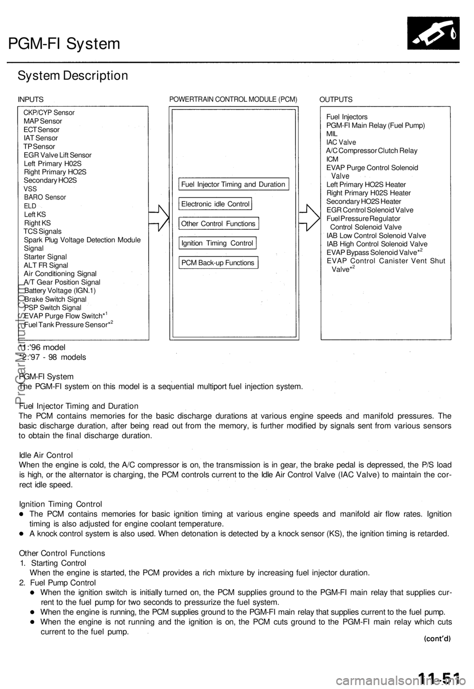
System Descriptio n
INPUTS POWERTRAI N CONTRO L MODUL E (PCM ) OUTPUT S
Fue l Injector s
PGM-F I Mai n Rela y (Fue l Pump )
MILIAC Valv eA/C Compresso r Clutc h Rela yICMEVA P Purg e Contro l Solenoi dValveLeft Primar y HO2 S Heate r
Righ t Primar y H02 S Heate r
Secondar y HO2 S Heate r
EG R Contro l Solenoi d Valv e
Fue l Pressur e Regulato r
Contro l Solenoi d Valv e
IA B Lo w Contro l Solenoi d Valv e
IA B Hig h Contro l Solenoi d Valv e
EVA P Bypas s Solenoi d Valve*
2
EVA P Contro l Caniste r Ven t Shu t
Valve*2
*1:'9 6 mode l
*2:'97 - 9 8 model s
PGM-F I Syste m
Th e PGM-F I syste m o n thi s mode l i s a sequentia l multipor t fue l injectio n system .
Fue l Injecto r Timin g an d Duratio n
Th e PC M contain s memorie s fo r th e basi c discharg e duration s a t variou s engin e speed s an d manifol d pressures . Th e
basi c discharg e duration , afte r bein g rea d ou t fro m th e memory , i s furthe r modifie d b y signal s sen t fro m variou s sensor s
t o obtai n th e fina l discharg e duration .
Idl e Ai r Contro l
Whe n th e engin e is cold , th e A/ C compresso r i s on , th e transmissio n i s i n gear , th e brak e peda l i s depressed , th e P/ S loa d
i s high , o r th e alternato r i s charging , th e PC M control s curren t t o th e Idl e Ai r Contro l Valv e (IA C Valve ) t o maintai n th e cor -
rec t idl e speed .
Ignitio n Timin g Contro l
Th e PC M contain s memorie s fo r basi c ignitio n timin g a t variou s engin e speed s an d manifol d ai r flo w rates . Ignitio n
timin g i s als o adjuste d fo r engin e coolan t temperature .
A knoc k contro l syste m is als o used . Whe n detonatio n is detecte d b y a knoc k senso r (KS) , th e ignitio n timin g is retarded .
Othe r Contro l Function s
1 . Startin g Contro l
Whe n th e engin e is started , th e PC M provide s a ric h mixtur e b y increasin g fue l injecto r duration .
2 . Fue l Pum p Contro l
Whe n th e ignitio n switc h i s initiall y turne d on , th e PC M supplie s groun d t o th e PGM-F I mai n rela y tha t supplie s cur -
ren t t o th e fue l pum p fo r tw o second s t o pressuriz e th e fue l system .
Whe n th e engin e is running , th e PC M supplie s groun d to th e PGM-F I mai n rela y tha t supplie s curren t t o th e fue l pump .
Whe n th e engin e i s no t runnin g an d th e ignitio n i s on , th e PC M cut s groun d t o th e PGM-F I mai n rela y whic h cut s
curren t t o th e fue l pump .
CKP/CY P Senso rMAP Senso r
EC T Senso r
IA T Senso r
T P Senso r
EG R Valv e Lif t Senso r
Lef t Primar y H02 S
Righ t Primar y HO2 S
Secondar y HO2 S
VSSBAR O Senso rELDLef t K S
Righ t K S
TC S Signal s
Spar k Plu g Voltag e Detectio n Modul e
Signa l
Starte r Signa l
AL T F R Signa l
Air Conditionin g Signa lA/T Gea r Positio n Signa l
Batter y Voltag e (IGN.1 )
Brak e Switc h Signa l
PS P Switc h Signa l
EVA P Purg e Flo w Switch*
1
Fue l Tan k Pressur e Sensor*2
PC M Back-u p Function s
Ignitio
n Timin g Contro l
Othe
r Contro l Function s
Electroni
c idl e Contro l
Fue
l Injecto r Timin g an d Duratio n
ProCarManuals.com
Page 200 of 1771
PGM-FI System
System Description (cont'd)
3. Fuel Cut-off Control
During deceleration with the throttle valve closed, current to the fuel injectors is cut off to improve fuel economy at
speeds over 1,000 rpm.
Fuel cut-off action also takes place when engine speed exceeds 6,500 rpm, regardless of the position of the throttle
valve, to protect the engine from over-revving.
4. A/C Compressor Clutch Relay .
When the PCM receives a demand for cooling from the air conditioning system, it delays the compressor from being
energized, and enriches the mixture to assure a smooth transition to the A/C mode.
5. Evaporative Emission (EVAP) Purge Control Solenoid Valve
'96 model: When the engine coolant temperature is below 158°F (70°C), the PCM controls the EVAP purge control
solenoid valve which cuts vacuum to the EVAP purge control canister diaphragm.
'97 - 98 models: When the engine coolant temperature is above 99°F (37°C), the PCM controls the EVAP purge control
solenoid valve which controls vacuum to the EVAP purge control canister.
6. Intake Air Bypass (IAB) Low Control Solenoid Valve, Intake Air Bypass (IAB) High Control Solenoid Valve
When engine speed is below 3,350 rpm, the IAB High Control Solenoid Valve and IAB Low Control Solenoid Valve are
activated by a signal from the PCM. Intake air flows through a long chamber path, increasing torque at low RPM.
When engine speed is 3,350 - 3,950 rpm, the IAB Low Control Solenoid Valve is deactivated by the PCM. Intake air
flows through a short chamber path, increasing mid-range torque.
When the engine rpm is above 3,950 rpm, the IAB Low Control Solenoid Valve and IAB High Control Solenoid Valve are
deactivated by the PCM. This creates a very short intake path and increases high-speed torque.
7. Exhaust Gas Recirculation (EGR) Control Solenoid Valve
When the EGR is required for control of oxides of nitrogen (NOx) emissions, the PCM controls the EGR control solenoid
valve which supplies regulated vacuum to the EGR valve.
ECM Fail-safe/Back-up Functions
1. Fail-safe Function
When an abnormality occurs in a signal from a sensor, the PCM ignores that signal and assumes a pre-programmed
value for that sensor that allows the engine to continue to run.
2. Back-up Function
When an abnormality occurs in the PCM itself, the fuel injectors are controlled by a back-up circuit independent of the
system in order to permit minimal driving.
3. Self-diagnosis Function [Malfunction Indicator Lamp (MIL)]
When an abnormality occurs in a signal from a sensor, the PCM supplies ground for the MIL and stores the DTC in
erasable memory. When the ignition is initially turned on, the PCM supplies ground for the MIL for two seconds to
check the MIL bulb condition.
4. Two Driving Cycle Detection Method
To prevent false indications, the two driving cycle detection method is used for the H02S, fuel metering-related, idle
control system, ECT sensor, EGR system, TWC, EVAP control system and other self-diagnostic functions. When an
abnormality occurs, the PCM stores it in its memory. When the same abnormality recurs after the ignition switch is
turned OFF and ON (II) again, the PCM informs the driver by lighting the MIL.
However, to ease troubleshooting, this function is cancelled when you short the service check connector. The MIL will
then blink immediately when an abnormality occurs.ProCarManuals.com
Page 202 of 1771
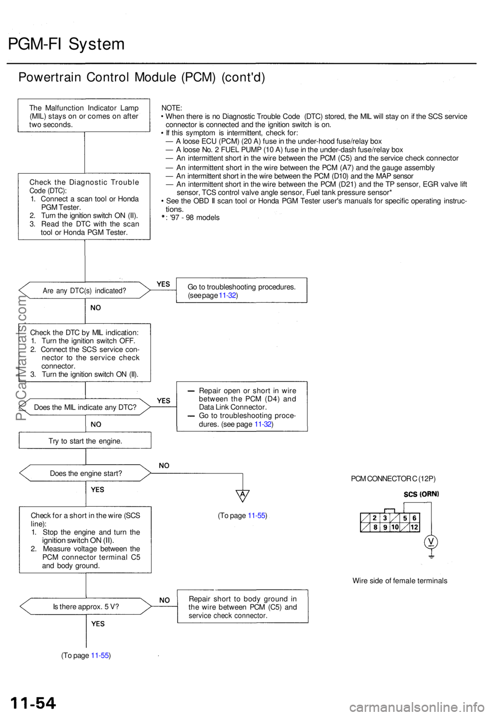
PGM-FI Syste m
Powertrai n Contro l Modul e (PCM ) (cont'd )
The Malfunctio n Indicato r Lam p
(MIL ) stay s o n o r come s o n afte r
tw o seconds .
Chec k th e Diagnosti c Troubl e
Code (DTC) :1. Connec t a sca n too l o r Hond a
PG M Tester .
2 . Tur n th e ignitio n switc h O N (II) .
3 . Rea d th e DT C wit h th e sca n
too l o r Hond a PG M Tester .
Are an y DTC(s ) indicated ?
Check th e DT C b y MI L indication :
1 . Tur n th e ignitio n switc h OFF .
2 . Connec t th e SC S servic e con -
necto r t o th e servic e chec k
connector .
3 . Tur n th e ignitio n switc h O N (II) .
Doe s th e MI L indicat e an y DTC ?
Tr y t o star t th e engine .
Doe s th e engin e start ?
NOTE :When ther e is n o Diagnosti c Troubl e Cod e (DTC ) stored , th e MI L wil l sta y o n if th e SC S servic e
connecto r i s connecte d an d th e ignitio n switc h is on .
I f thi s sympto m is intermittent , chec k for :
— A loos e EC U (PCM ) (2 0 A ) fus e in th e under-hoo d fuse/rela y bo x
— A loos e No . 2 FUE L PUM P (1 0 A ) fus e in th e under-das h fuse/rela y bo x
— A n intermitten t shor t i n th e wire betwee n th e PC M (C5 ) an d th e servic e chec k connecto r
— A n intermitten t shor t i n th e wire betwee n th e PC M (A7 ) an d th e gaug e assembl y
— A n intermitten t shor t i n th e wir e betwee n th e PC M (D10 ) an d th e MA P senso r
— A n intermitten t shor t i n th e wire betwee n th e PC M (D21 ) an d th e T P sensor , EG R valv e lif t
sensor , TC S contro l valv e angl e sensor , Fue l tan k pressur e sensor *
Se e th e OB D II sca n too l o r Hond a PG M Teste r user' s manual s fo r specifi c operatin g instruc -
tions.: '9 7 - 9 8 model s
G o to troubleshootin g procedures .
(se e pag e 11-32 )
Repai r ope n o r shor t i n wir e
betwee n the PCM (D4 ) an d
Dat a Lin k Connector .
G o to troubleshootin g proce -
dures . (se e pag e 11-32 )
PCM CONNECTO R C (12P )
Chec k fo r a shor t i n th e wir e (SC S
line) :
1 . Sto p th e engin e an d tur n th e
ignitio n switc h O N (II) .2. Measur e voltag e betwee n th e
PC M connecto r termina l C 5
an d bod y ground . (T
o pag e 11-55 )
Wire sid e o f femal e terminal s
I s ther e approx . 5 V ?
(T o pag e 11-55 ) Repai
r shor t t o bod y groun d in
th e wir e betwee n PC M (C5 ) an d
servic e chec k connector .
ProCarManuals.com
Page 204 of 1771
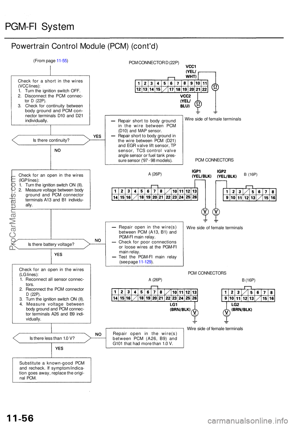
PGM-FI Syste m
Powertrai n Contro l Modul e (PCM ) (cont'd )
(From pag e 11-55 )
Chec k fo r a shor t i n th e wire s
(VC C lines) :
1 . Tur n th e ignitio n switc h OFF .
2 . Disconnec t th e PC M connec -
tor D (22P) .3. Chec k fo r continuit y betwee nbody groun d an d PC M con -necto r terminal s D1 0 an d D2 1individually .
Is ther e continuity ?
I s ther e batter y voltage ?
Chec k fo r a n ope n i n th e wire s
(L G lines) :
1 . Reconnec t al l senso r connec -
tors .
2 . Reconnec t th e PC M connecto r
D (22P) .3. Tur n th e ignitio n switc h O N (II) .
4 . Measur e voltag e betwee n
bod y groun d an d PC M connec -
to r terminal s A2 6 an d B 9 indi -
vidually .
I s ther e les s tha n 1. 0 V ?
Substitut e a known-goo d PC M
an d recheck . I f symptom/indica -
tio n goe s away , replac e th e origi -
nal PCM .
PCM CONNECTO R D (22P )
Repai r shor t t o bod y groun d
i n th e wir e betwee n PC M
(D10 ) an d MA P sensor .Repair shor t t o bod y groun d in
th e wir e betwee n PC M (D21 )
an d EG R valv e lif t sensor , T P
sensor , TC S contro l valv e
angl e senso r o r fue l tan k pres -
sur e senso r ('9 7 - 9 8 models) .Wir
e sid e o f femal e terminal s
A (26P)
PCM CONNECTOR S
Repair ope n i n th e wire(s )
betwee n PC M (A13 , B1 ) an d
PGM-F I mai n relay .
Chec k fo r poo r connection s
o r loos e wire s a t th e PGM-F I
mai n relay .
Tes t th e PGM-F I mai n rela y
(se e pag e 11-129 ). Wir
e sid e o f femal e terminal s
PCM CONNECTOR S
A (26P)B (16P)
Repai r ope n i n th e wire(s )
betwee n PC M (A26 , B9 ) an d
G10 1 tha t ha d mor e tha n 1. 0 V .Wir e sid e o f femal e terminal s
Check fo r a n ope n i n th e wire s
(IG P lines) :
1 . Tur n th e ignitio n switc h O N (II) .
2 . Measur e voltag e betwee n bod y
groun d an d PC M connecto r
terminal s A1 3 an d B 1 individu -
ally .B (16P )
ProCarManuals.com
Page 224 of 1771
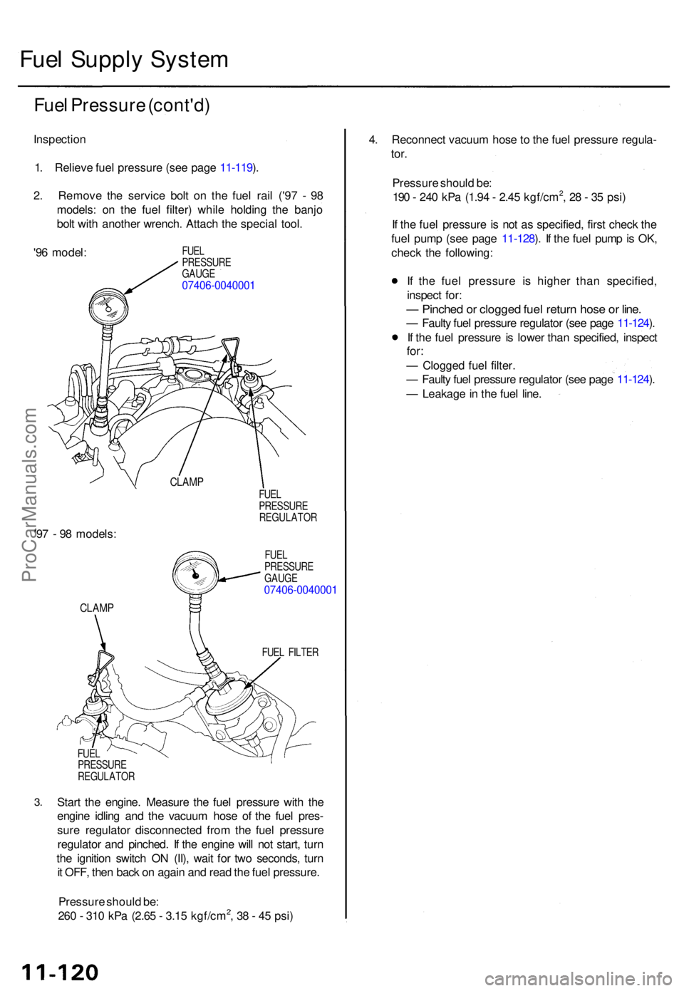
Fuel Suppl y Syste m
Fuel Pressur e (cont'd )
Inspectio n
1 . Reliev e fue l pressur e (se e pag e 11-119 ).
2 . Remov e th e servic e bol t o n th e fue l rai l ('9 7 - 9 8
models : o n th e fue l filter ) whil e holdin g th e banj o
bol t wit h anothe r wrench . Attac h th e specia l tool .
'9 6 model :
FUEL
PRESSUR E
GAUG E
07406-004000 1
CLAMP
'97 - 9 8 models :
CLAMP
FUEL
PRESSUR E
REGULATO R
FUE L
PRESSUR E
GAUG E
07406-004000 1
FUEL FILTE R
3.
FUE L
PRESSUR E
REGULATO R
Start th e engine . Measur e th e fue l pressur e wit h th e
engin e idlin g an d th e vacuu m hos e o f th e fue l pres -
sur e regulato r disconnecte d fro m th e fue l pressur e
regulato r an d pinched . I f th e engin e wil l no t start , tur n
th e ignitio n switc h O N (II) , wai t fo r tw o seconds , tur n
i t OFF , the n bac k o n agai n an d rea d th e fue l pressure .
Pressur e shoul d be :
26 0 - 31 0 kP a (2.6 5 - 3.1 5 kgf/cm
2, 3 8 - 4 5 psi ) 4
. Reconnec t vacuu m hos e t o th e fue l pressur e regula -
tor.
Pressur e shoul d be :
19 0 - 24 0 kP a (1.9 4 - 2.4 5 kgf/cm2, 2 8 - 3 5 psi )
I f th e fue l pressur e is no t a s specified , firs t chec k th e
fue l pum p (se e pag e 11-128 ). I f th e fue l pum p is OK ,
chec k th e following :
I f th e fue l pressur e i s highe r tha n specified ,
inspec t for :
— Pinche d o r clogge d fue l retur n hos e o r line .
— Fault y fue l pressur e regulato r (se e pag e 11-124 ).
I f th e fue l pressur e i s lowe r tha n specified , inspec t
for:
— Clogge d fue l filter .
— Fault y fue l pressur e regulato r (se e pag e 11-124 ).
— Leakag e in th e fue l line .
ProCarManuals.com
Page 225 of 1771
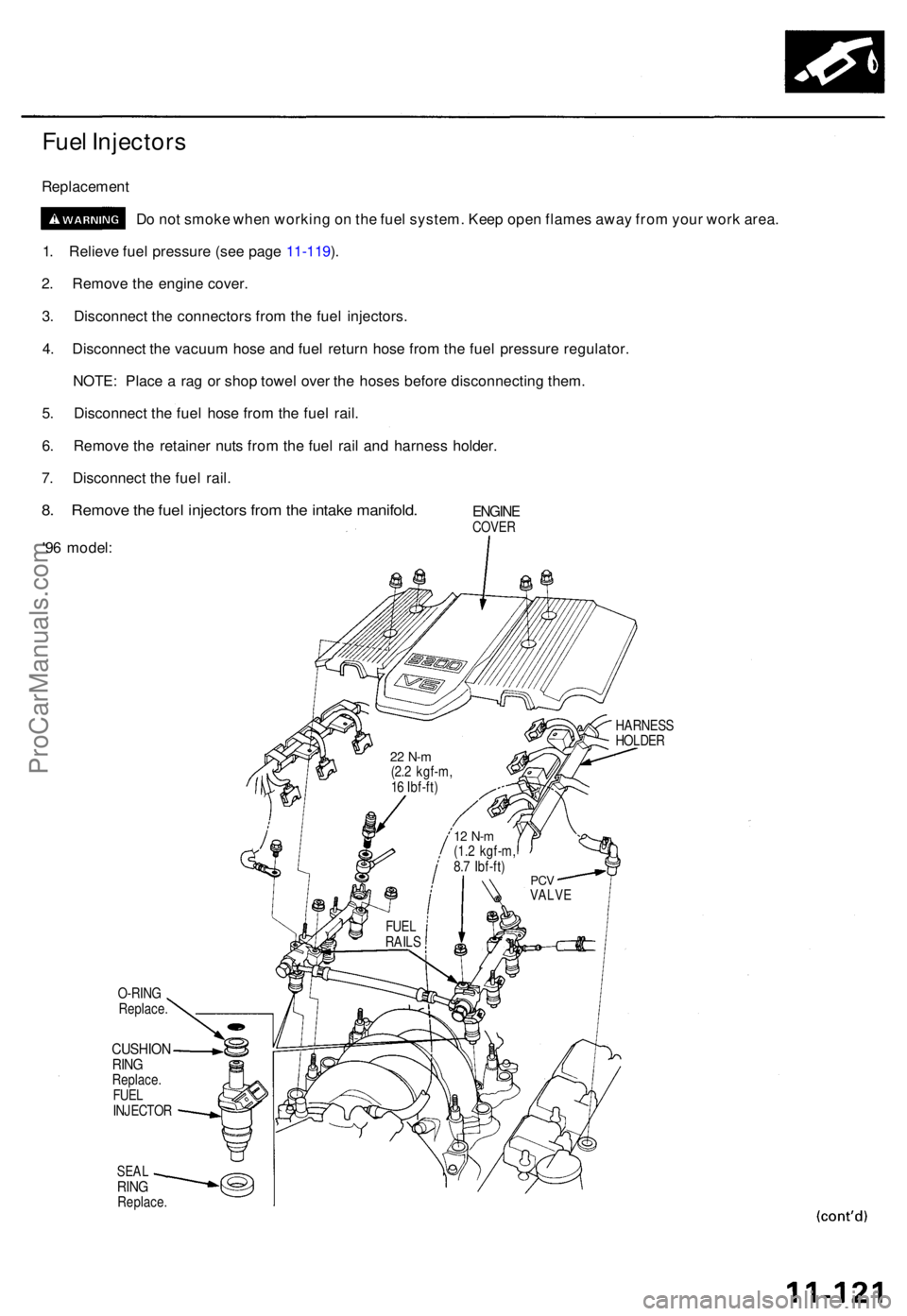
Fuel Injector s
Replacemen t
Do no t smok e whe n workin g o n th e fue l system . Kee p ope n flame s awa y fro m you r wor k area .
1 . Reliev e fue l pressur e (se e pag e 11-119 ).
2 . Remov e th e engin e cover .
3 . Disconnec t th e connector s fro m th e fue l injectors .
4 . Disconnec t th e vacuu m hos e an d fue l retur n hos e fro m th e fue l pressur e regulator .
NOTE : Plac e a ra g o r sho p towe l ove r th e hose s befor e disconnectin g them .
5 . Disconnec t th e fue l hos e fro m th e fue l rail .
6 . Remov e th e retaine r nut s fro m th e fue l rai l an d harnes s holder .
7 . Disconnec t th e fue l rail .
8. Remov e th e fue l injector s fro m th e intak e manifold .
'96 model :
ENGINECOVER
O-RIN G
Replace .
CUSHIO NRINGReplace .
FUE L
INJECTO R
SEALRINGReplace .
HARNES S
HOLDE R
FUE L
RAIL S
PCVVALV E
12 N- m(1.2 kgf-m ,
8. 7 Ibf-ft )
22 N- m(2.2 kgf-m ,
1 6 Ibf-ft )
ProCarManuals.com