1995 ACURA TL ECO mode
[x] Cancel search: ECO modePage 314 of 1771
Linear Solenoi d
Test
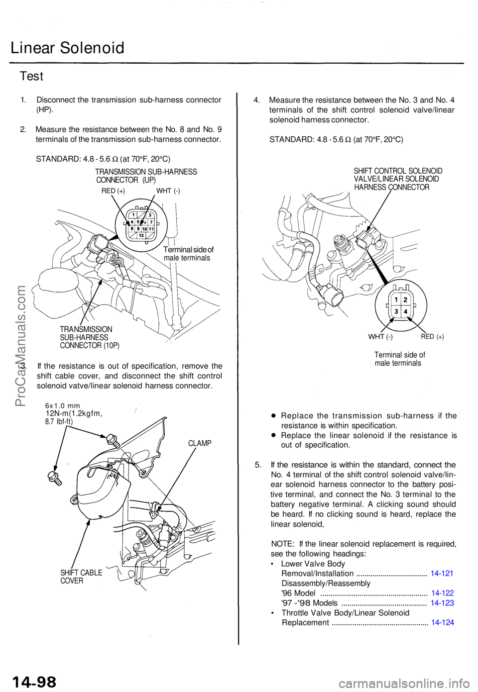
1. Disconnec t th e transmissio n sub-harnes s connecto r
(HP).
2. Measur e th e resistanc e betwee n th e No . 8 an d No . 9
terminal s o f th e transmissio n sub-harnes s connector .
STANDARD : 4. 8 - 5. 6 W (a t 70°F , 20°C )
TRANSMISSIO N SUB-HARNES SCONNECTOR (UP )
RED (+ ) WH T (- )
Termina l sid e o fmal e terminal s
TRANSMISSIO NSUB-HARNESSCONNECTOR (10P )
3. I f th e resistanc e i s ou t o f specification , remov e th e
shif t cabl e cover , an d disconnec t th e shif t contro l
solenoi d vatve/linea r solenoi d harnes s connector .
6x1.0 mm12N-m(1.2kgfm ,8.7 Ibf-ft )
CLAM P
SHIFT CABL ECOVER
4. Measur e th e resistanc e betwee n th e No . 3 an d No . 4
terminal s o f th e shif t contro l solenoi d valve/linea r
solenoi d harnes s connector .
STANDARD : 4. 8 - 5. 6 W (a t 70°F , 20°C )
SHIFT CONTRO L SOLENOI DVALVE/LINEA R SOLENOI DHARNESS CONNECTO R
WHT (- )RE D (+ )
Termina l sid e o fmal e terminal s
• Replac
e th e transmissio n sub-harnes s i f th e
resistanc e is withi n specification .
• Replac
e th e linea r solenoi d i f th e resistanc e i s
ou t o f specification .
5. I f th e resistanc e is withi n th e standard , connec t th e
No . 4 termina l o f th e shif t contro l solenoi d valve/lin -
ea r solenoi d harnes s connecto r t o th e batter y posi -
tiv e terminal , an d connec t th e No . 3 termina l t o th e
batter y negativ e terminal . A clickin g soun d shoul d
b e heard . I f n o clickin g soun d i s heard , replac e th e
linea r solenoid ,
NOTE : I f th e linea r solenoi d replacemen t i s required ,
se e th e followin g headings :
• Lowe r Valv e Bod y
Removal/Installatio n
................................... 14-12 1
Disassembly/Reassembl y
'96 Mode l ................................................... . 14-12 2
'97 -'9 8 Model s ......................................... . 14-12 3
• Throttl e Valv e Body/Linea r Solenoi d
Replacemen t
.............................................. . 14-12 4
ProCarManuals.com
Page 328 of 1771
Fluid Level
Checking/Changing
Checking
NOTE: Check the fluid level with the engine at normal
operating temperature (the radiator fan comes on).
1. Park the vehicle on level ground. Turn off the
engine.
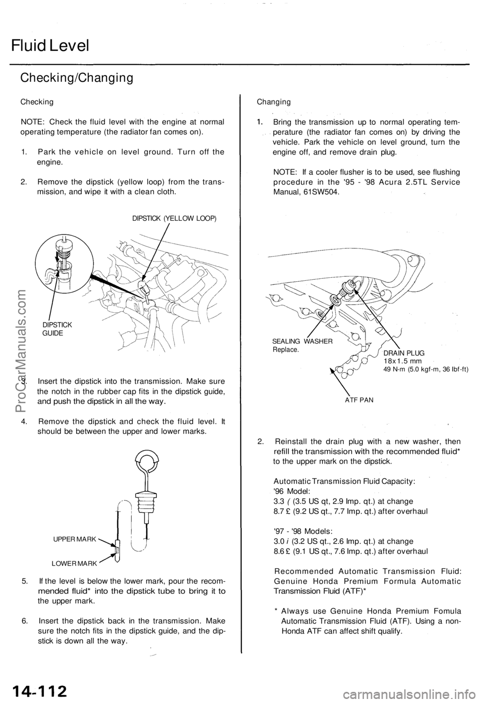
2. Remove the dipstick (yellow loop) from the trans-
mission, and wipe it with a clean cloth.
DIPSTICK (YELLOW LOOP)
DIPSTICK
GUIDE
3. Insert the dipstick into the transmission. Make sure
the notch in the rubber cap fits in the dipstick guide,
and push the dipstick in all the way.
4. Remove the dipstick and check the fluid level. It
should be between the upper and lower marks.
UPPER MARK
LOWER MARK
5. If the level is below the lower mark, pour the recom-
mended fluid* into the dipstick tube to bring it to
the upper mark.
6. Insert the dipstick back in the transmission. Make
sure the notch fits in the dipstick guide, and the dip-
stick is down all the way.
Changing
Bring the transmission up to normal operating tem-
perature (the radiator fan comes on) by driving the
vehicle. Park the vehicle on level ground, turn the
engine off, and remove drain plug.
NOTE: If a cooler flusher is to be used, see flushing
procedure in the '95 - '98 Acura 2.5TL Service
Manual, 61SW504.
SEALING WASHER
Replace.
DRAIN PLUG
18x1.5 mm
49 N-m (5.0 kgf-m, 36 Ibf-ft)
ATF PAN
2. Reinstall the drain plug with a new washer, then
refill the transmission with the recommended fluid*
to the upper mark on the dipstick.
Automatic Transmission Fluid Capacity:
'96 Model:
3.3 ( (3.5 US qt, 2.9 Imp. qt.) at change
8.7 £ (9.2 US qt., 7.7 Imp. qt.) after overhaul
'97 - '98 Models:
3.0 i (3.2 US qt., 2.6 Imp. qt.) at change
8.6 £ (9.1 US qt., 7.6 Imp. qt.) after overhaul
Recommended Automatic Transmission Fluid:
Genuine Honda Premium Formula Automatic
Transmission Fluid (ATF)*
* Always use Genuine Honda Premium Fomula
Automatic Transmission Fluid (ATF). Using a non-
Honda ATF can affect shift qualify.ProCarManuals.com
Page 337 of 1771
NOTE:
Clean al l part s thoroughl y in solven t o r carbureto r cleaner , an d dr y wit h compresse d air .
Blo w ou t al l passages .
Do no t le t th e chec k ball s fal l ou t o f th e mai n valv e bod y whe n removin g th e mai n valv e body .
Coat al l part s wit h AT F befor e reassembly .
Replace th e O-ring s an d filters .
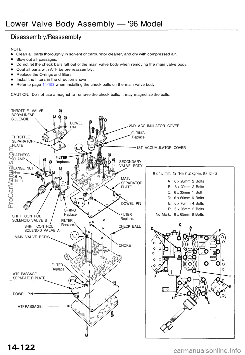
Install th e filter s i n th e directio n shown .
Refer t o pag e 14-15 3 whe n installin g th e chec k ball s o n th e mai n valv e body .
CAUTION : D o no t us e a magne t t o remov e th e chec k balls ; i t ma y magnetiz e th e balls .
THROTTL E VALV E
BODY/LINEA R
SOLENOID
THROTTL ESEPARATO RPLATE
HARNES S
CLAM P 2N
D ACCUMULATO R COVE R
O-RINGReplace .
1S T ACCUMULATO R COVE R
FLANG E NU T
6N-m(0.6 kgf-m ,
4 Ibf-ft ) SECONDAR
Y
VALV E BOD Y
AT F PASSAG E
SEPARATO R PLAT E
DOWE L PI N
AT F PASSAG E
MAINSEPARATO RPLATE
DOWE L PI N
FILTE RReplace .
CHEC K BAL L
CHOK E 6
x 1. 0 mm : 1 2 N- m (1. 2 kgf-m , 8. 7 Ibf-ft )
A: 6 x 20m m 2 Bolt s
B: 6 x 30m m 2 Bolt s
C: 6 x 35m m 1 Bol t
D: 6 x 60m m 6 Bolt s
E: 6 x 70m m 4 Bolt s
F: 6 x 95m m 2 Bolt s
No Mark : 6 x 65m m 8 Bolt s
DOWE LPIN
MAI N VALV E BOD Y
FILTERReplace. '
O-RING
Replace .
SHIF T CONTRO L
SOLENOI D VALV E B
SHIF T CONTRO L
SOLENOI D VALV E A
FILTE RReplace .
Lower Valv e Bod y Assembl y — '96 Mode l
Disassembly/Reassembl y
ProCarManuals.com
Page 338 of 1771
Lower Valv e Bod y Assembl y — '97 - '9 8 Model s
Disassembly/Reassembl y
NOTE:
Clean al l part s thoroughl y in solven t o r carbureto r cleaner , an d dr y wit h compresse d air .
Blo w ou t al l passages .
D o no t le t th e chec k ball s fal l ou t o f th e mai n valv e bod y whe n removin g th e mai n valv e body .
Coa t al l part s wit h AT F befor e reassembly .
Replac e th e 0-ring s an d filters .
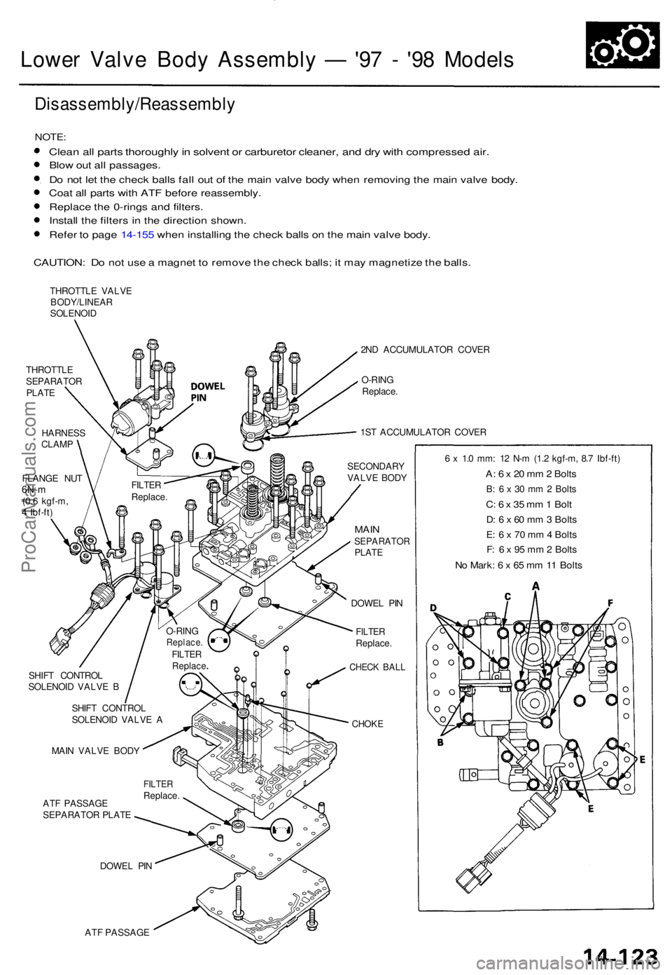
Instal l th e filter s i n th e directio n shown .
Refe r t o pag e 14-15 5 whe n installin g th e chec k ball s o n th e mai n valv e body .
CAUTION : D o no t us e a magne t t o remov e th e chec k balls ; i t ma y magnetiz e th e balls .
THROTTL E VALV E
BODY/LINEA R
SOLENOI D
THROTTL E
SEPARATO R
PLAT E
HARNES S
CLAM P
FLANG E NU T
6N-m(0.6 kgf-m ,
4 Ibf-ft )
O-RING
Replace .FILTERReplac e
SHIFT CONTRO L
SOLENOI D VALV E A
SHIF
T CONTRO L
SOLENOI D VALV E B
AT F PASSAG E
SEPARATO R PLAT E
DOWE L PI N
AT F PASSAG E 2N
D ACCUMULATO R COVE R
O-RIN G
Replace .
1S T ACCUMULATO R COVE R
SECONDAR Y
VALV E BOD Y
MAINSEPARATO RPLATE
DOWE L PI N
FILTE RReplace .
CHECK BAL L
CHOK E
6 x 1. 0 mm : 1 2 N- m (1. 2 kgf-m , 8. 7 Ibf-ft )
A: 6 x 20 m m 2 Bolt s
B: 6 x 30 m m 2 Bolt s
C: 6 x 35 m m 1 Bol t
D: 6 x 60 m m 3 Bolt s
E : 6 x 70 m m 4 Bolt s
F: 6 x 95 m m 2 Bolt s
No Mark : 6 x 65 m m 11 Bolt s
FILTE RReplace .
MAI
N VALV E BOD Y
FILTE
R
Replace .
ProCarManuals.com
Page 365 of 1771
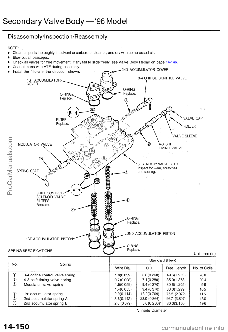
Secondary Valv e Bod y — '96 Mode l
Disassembly/lnspection/Reassembl y
NOTE:
Clean al l part s thoroughl y in solven t o r carbureto r cleaner , an d dr y wit h compresse d air .
Blo w ou t al l passages .
Chec k al l valve s fo r fre e movement . I f an y fai l t o slid e freely , se e Valv e Bod y Repai r o n pag e 14-146 .
Coa t al l part s wit h AT F durin g assembly .
Instal l th e filter s i n th e directio n shown .
2ND ACCUMULATO R COVE R
1ST ACCUMULATO RCOVER
3-4 ORIFIC E CONTRO L VALV E
MODULATO R VALV E4-3 SHIF TTIMING VALV E
SPRING SEA T
SPRIN G SPECIFICATION S
VALVE CA P
ROLLE R
VALVE SLEEV E
SECONDAR Y VALV E BOD YInspec t fo r wear , scratche sand scoring .
SHIFT CONTRO LSOLENOID VALV EFILTER SReplace .
1ST ACCUMULATO R PISTO N
2ND ACCUMULATO R PISTO N
O-RINGReplace .Unit: m m (in )
No.Sprin g
3-4 orific e contro l valv e sprin g
4- 3 shif t timin g valv e sprin g
Modulato r valv e sprin g
1s t accumulato r sprin g
2n d accumulato r sprin g A
2n d accumulato r sprin g B
Standar d (New )
Wire Dia .
1.0(0.039 )
0.7 (0.028 )
1.5(0.059 )
1.4(0.055 )
2.9(0.114 )
3.6(0.142)
2.0 (0.079 )
O.D.
6.6 (0.260 )
7. 1 (0.280 )
9.4 (0.370 )
9. 4 (0.370 )
18.0(0.709 )
22.0 (0.866 )
6.6 (0.260) *Fre
e Lengt h
49.6(1.953 )
35.0(1.378)
30.6(1.205 )
33.0(1.299)
75.5 (2.972 )
96.7 (3.807 )
80.0(3.150 )
No. o f Coil s
26.8
20. 4
9.9
10. 5
11. 5
13. 0
19. 6
*: insid e Diamete r
FILTERReplace .
O-RING-Replace
O-RINGReplace .
O-RINGReplace .
ProCarManuals.com
Page 366 of 1771
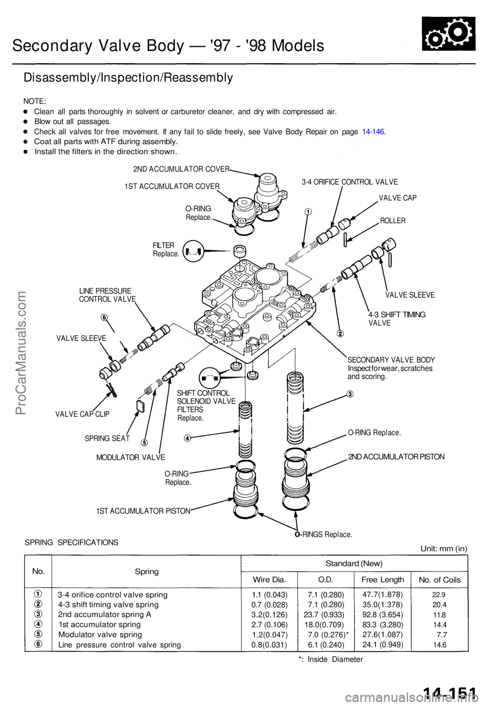
Secondary Valv e Bod y — '97 - '9 8 Model s
Disassembly/Inspection/Reassembl y
NOTE:
Clea n al l part s thoroughl y i n solven t o r carbureto r cleaner , an d dr y wit h compresse d air .
Blo w ou t al l passages .
Chec k al l valve s fo r fre e movement . I f an y fai l t o slid e freely , se e Valv e Bod y Repai r o n pag e 14-146 .
Coat al l part s wit h AT F durin g assembly .
Install th e filter s in th e directio n shown .
2ND ACCUMULATOR COVER
1ST ACCUMULATOR COVER
O-RIN GReplace .
3-4 ORIFIC E CONTRO L VALV E
VALVE CA P
ROLLE R
LINE PRESSUR ECONTROL VALV E
VALVE SLEEV E
VALVE CA P CLI P
SHIF T CONTRO LSOLENOID VALV EFILTER SReplace .
VALVE SLEEV E
4-3 SHIF T TIMIN GVALV E
SECONDAR Y VALV E BOD YInspec t fo r wear , scratche sand scoring .
SPRING SEA T
MODULATO R VALV E
O-RING Replace .
2ND ACCUMULATO R PISTO N
1ST ACCUMULATO R PISTO N
SPRING SPECIFICATION SRINGS Replace .
Unit: m m (in )
No.Sprin g
3-4 orific e contro l valv e sprin g
4-3 shif t timin g valv e sprin g
2nd accumulato r sprin g A
1s t accumulato r sprin g
Modulato r valv e sprin g
Line pressur e contro l valv e sprin g
Standar d (New )
Wire Dia .
1.1 (0.043 )
0. 7 (0.028 )
3.2(0.126 )
2. 7 (0.106 )
1.2(0.047 )
0.8(0.031)
O.D.
7.1 (0.280 )
7. 1 (0.280 )
23. 7 (0.933 )
18.0(0.709 )
7. 0 (0.276) *
6. 1 (0.240 )
Free Lengt h
47.7(1.878 )
35.0(1.378 )
92. 8 (3.654 )
83. 3 (3.280 )
27.6(1.087 )
24. 1 (0.949 )
No. o f Coil s
22.9
20. 4
11. 8
14. 4
7.7
14. 6
*: Insid e Diamete r
O-RINGReplac e
FILTERReplace .
ProCarManuals.com
Page 407 of 1771
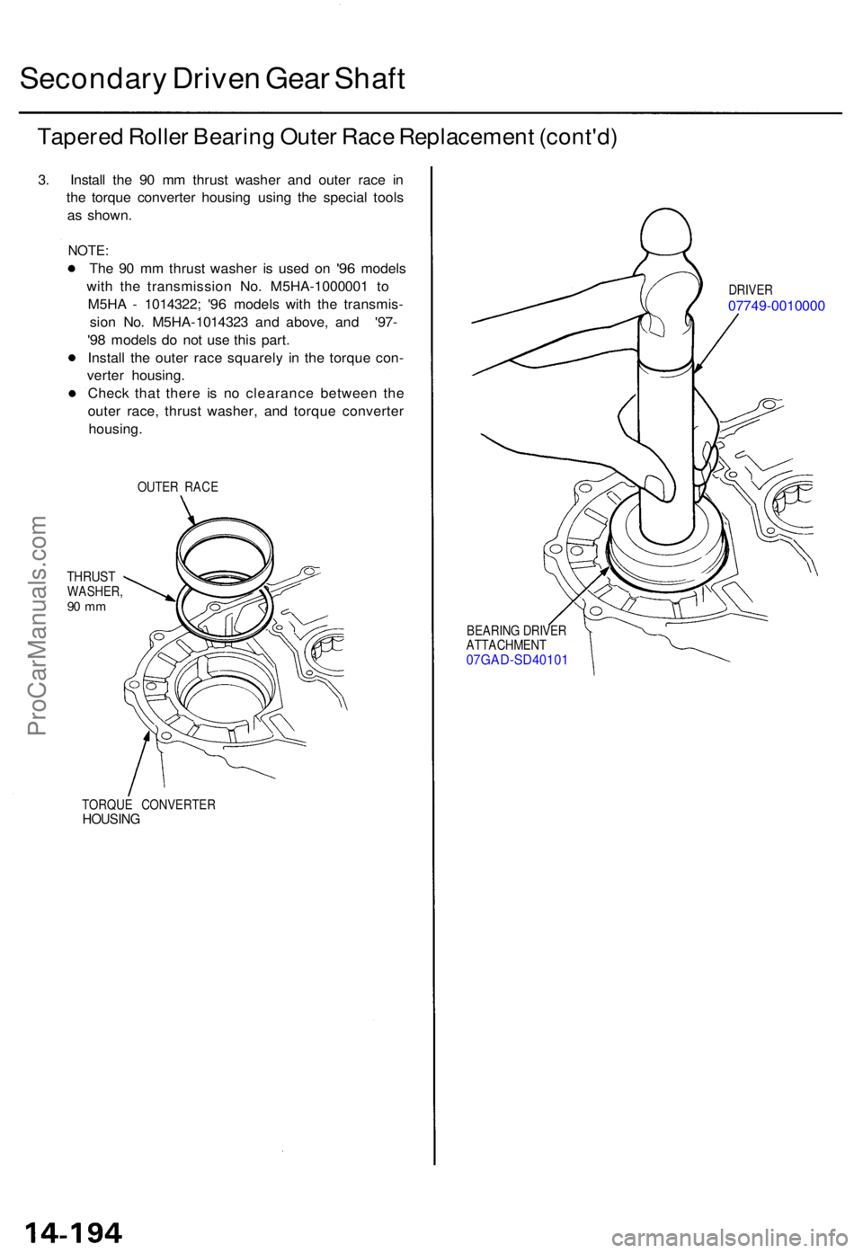
Secondary Drive n Gea r Shaf t
Tapere d Rolle r Bearin g Oute r Rac e Replacemen t (cont'd )
3. Instal l th e 9 0 m m thrus t washe r an d oute r rac e i n
th e torqu e converte r housin g usin g th e specia l tool s
a s shown .
NOTE:
The 9 0 m m thrus t washe r i s use d o n '9 6 model s
wit h th e transmissio n No . M5H A-100000 1 t o
M5H A - 1014322 ;
'96 model s wit h th e transmis -
sio n No .
M5H A-101432 3 an d above , an d ' '97-
'98 model s d o no t us e thi s part .
Instal l th e oute r rac e squarel y i n th e torqu e con -
verte r housing .
Chec k tha t ther e i s n o clearanc e betwee n th e
oute r race , thrus t washer , an d torqu e converte r
housing .
OUTER RAC E
THRUS TWASHER ,90 m m
TORQU E CONVERTE RHOUSING
DRIVER07749-001000 0
BEARING DRIVE R
ATTACHMEN T
07GAD-SD4010 1
ProCarManuals.com
Page 408 of 1771
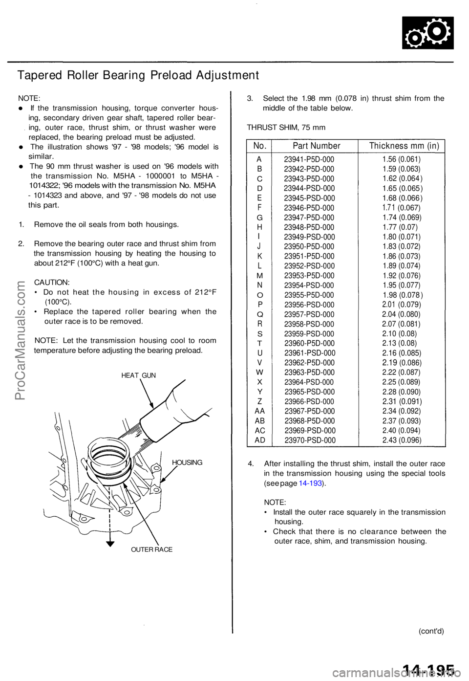
Tapered Rolle r Bearin g Preloa d Adjustmen t
NOTE:
• If th e transmissio n housing , torqu e converte r hous -
ing , secondar y drive n gea r shaft , tapere d rolle r bear -
ing , oute r race , thrus t shim , o r thrus t washe r wer e
replaced , th e bearin g preloa d mus t b e adjusted .
• The illustratio n show s '9 7 - '9 8 models ; '9 6 mode l i s
similar .
• The 9 0 m m thrus t washe r i s use d o n '9 6 model s wit h
th e transmissio n No . M5H A - 100000 1 t o M5H A -
1014322 ; '9 6 model s wit h th e transmissio n No . M5H A
- 101432 3 an d above , an d '9 7 - '9 8 model s d o no t us e
this part .
1. Remov e th e oi l seal s fro m bot h housings .
2 . Remov e th e bearin g oute r rac e an d thrus t shi m fro m
th e transmissio n housin g b y heatin g th e housin g t o
abou t 212° F (100°C ) wit h a hea t gun .
CAUTION :
• D o no t hea t th e housin g i n exces s o f 212° F
(100°C) .
• Replac e th e tapere d rolle r bearin g whe n th e
oute r rac e is to b e removed .
NOTE : Le t th e transmissio n housin g coo l t o roo m
temperatur e befor e adjustin g th e bearin g preload .
HEAT GU N
HOUSIN G
OUTER RAC E
3. Selec t th e 1.9 8 m m (0.07 8 in ) thrus t shi m fro m th e
middl e o f th e tabl e below .
THRUS T SHIM , 7 5 m m
No.
A
B
C
D
E
F
G
H
J
K
L
M
N
O
P
Q
R
S
T
U
V
W
X
Y
Z
AA
AB
AC
AD
Part Number
23941-P5D-000
23942-P5D-000
23943-P5D-000
23944-PSD-000
23945-PSD-000
23946-P5D-000
23947-P5D-000
23948-P5D-000 23949-PSD-000
23950-P5D-000
23951-P5D-000
23952-PSD-000
23953- P5D-000
23954-PSD-000
23955-P5D-000
23956-PSD-000
23957-PSD-000
23958-PSD-000
23959-PSD-000
23960-P5D-000
23961-PSD-000
23962-P5D-000 23963-P5D-000
23964-PSD-000
23965-PSD-000
23966-PSD-000
23967-P5D-000 23968-P5D-000
23969-PSD-000 23970-PSD -000
Thickness mm (in)
1.56 (0.061)
1.59 (0.063)
1.62 (0.064)
1.65 (0.06 5)
1.68 (0.06 6)
1.7 1 (0.067)
1.74 (0.069)
1.77 (0.07)
1.80 (0.071)
1.83 (0.072)
1.86 (0.073)
1.89 (0.074)
1.92 (0.076)
1.95 (0.077)
1.98 (0.07 8)
2.01 (0.079)
2.04 (0.080)
2.07 (0.081)
2.10 (0.08)
2.13 (0.08)
2.16 (0.085)
2.19 (0.086)
2.22 (0.087)
2.25 (0.089)
2.28 (0.090)
2.31 (0.091)
2.34 (0.092)
2.37 (0.093)
2.40 (0.094)
2.43 (0.096)
4. Afte r installin g th e thrus t shim , instal l th e oute r rac e
i n th e transmissio n housin g usin g th e specia l tool s
(se e pag e 14-193 ).
NOTE :
• Instal l th e oute r rac e squarel y i n th e transmissio n
housing .
• Chec k tha t ther e i s n o clearanc e betwee n th e
oute r race , shim , an d transmissio n housing .
(cont'd )
I
ProCarManuals.com