1995 ACURA TL ECO mode
[x] Cancel search: ECO modePage 882 of 1771
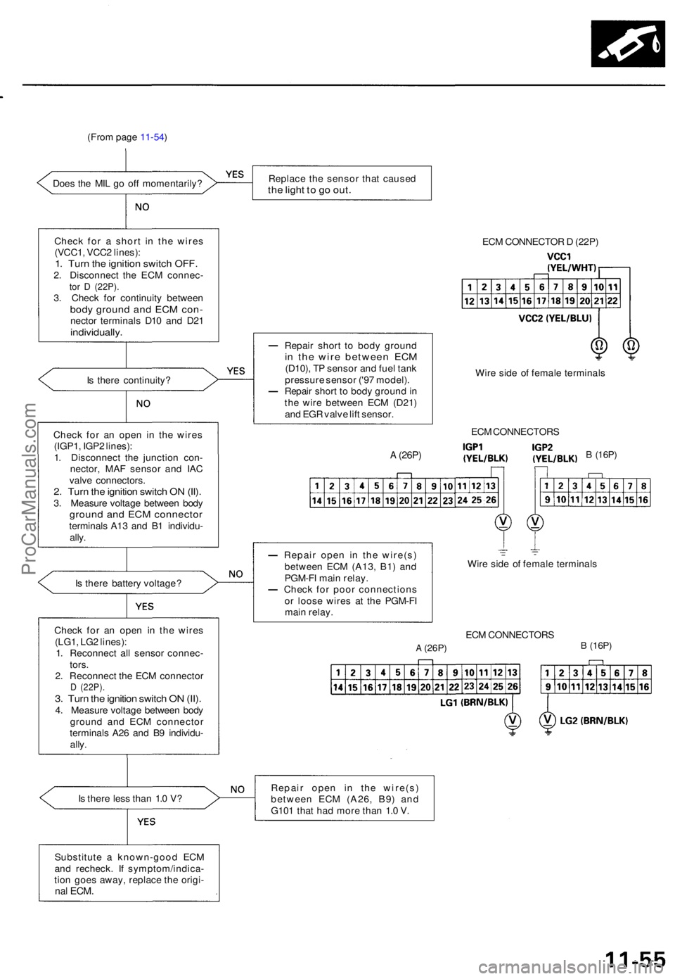
(From pag e 11-54 )
Doe s th e MI L g o of f momentarily ?
I s ther e batter y voltage ?
Chec k fo r a n ope n i n th e wire s
(LG1 , LG 2 lines) :
1 . Reconnec t al l senso r connec -
tors .
2 . Reconnec t th e EC M connecto r
D (22P) .3. Tur n th e ignitio n switc h O N (II) .4. Measur e voltag e betwee n bod y
groun d an d EC M connecto r
terminal s A2 6 an d B 9 individu -
ally .
I s ther e les s tha n 1. 0 V ?
Substitut e a known-goo d EC M
an d recheck . I f symptom/indica -
tio n goe s away , replac e th e origi -
nal ECM .
Replac e th e senso r tha t cause dthe ligh t t o g o out .
ECM CONNECTO R D (22P )
Repai r shor t t o bod y groun d
in th e wir e betwee n EC M(D10) , T P senso r an d fue l tan k
pressur e senso r ('9 7 model) .
Repai r shor t t o bod y groun d in
th e wir e betwee n EC M (D21 )
an d EG R valv e lif t sensor .
A (26P)
Repai r ope n i n th e wire(s )
betwee n EC M (A13 , B1 ) an d
PGM-F I mai n relay .
Chec k fo r poo r connection s
o r loos e wire s a t th e PGM-F I
mai n relay . Wir
e sid e o f femal e terminal s
EC M CONNECTOR S
A (26P)B (16P)
Repai r ope n i n th e wire(s )
betwee n EC M (A26 , B9 ) an d
G10 1 tha t ha d mor e tha n 1. 0 V . EC
M CONNECTOR S
B (16P)
Wire sid e o f femal e terminal s
Chec k fo r a n ope n i n th e wire s
(IGP1 , IGP 2 lines) :
1 . Disconnec t th e junctio n con -
nector , MA F senso r an d IA C
valv e connectors .
2. Tur n th e ignitio n switc h O N (II) .3. Measur e voltag e betwee n bod ygroun d an d EC M connecto rterminals A1 3 an d B 1 individu -
ally .I
s ther e continuity ?
Chec
k fo r a shor t i n th e wire s
(VCC1 , VCC 2 lines) :
1. Tur n th e ignitio n switc h OFF .2. Disconnec t th e EC M connec -tor D (22P) .3. Chec k fo r continuit y betwee nbody groun d an d EC M con -necto r terminal s D1 0 an d D2 1individually .
ProCarManuals.com
Page 904 of 1771
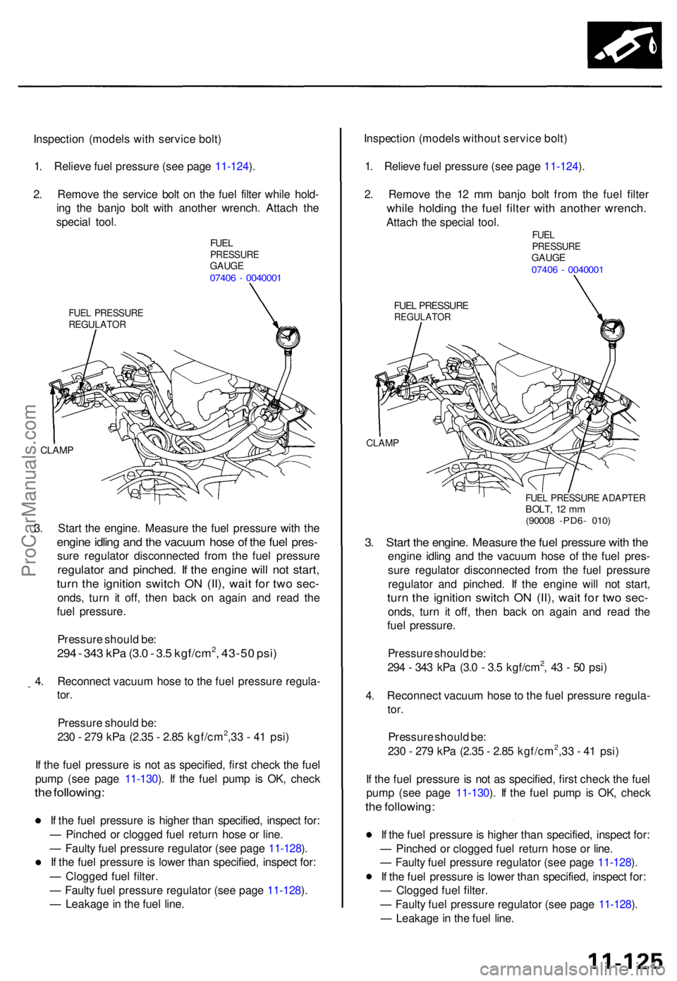
Inspection (model s wit h servic e bolt )
1 . Reliev e fue l pressur e (se e pag e 11-124 ).
2 . Remov e th e servic e bol t o n th e fue l filte r whil e hold -
in g th e banj o bol t wit h anothe r wrench . Attac h th e
specia l tool .
FUELPRESSUR EGAUGE07406 - 004000 1
FUEL PRESSUR EREGULATO R
CLAMP
3. Star t th e engine . Measur e th e fue l pressur e wit h th e
engin e idlin g an d th e vacuu m hos e o f th e fue l pres -
sure regulato r disconnecte d fro m th e fue l pressur e
regulator an d pinched . I f th e engin e wil l no t start ,
turn th e ignitio n switc h O N (II) , wai t fo r tw o sec -
onds , tur n i t off , the n bac k o n agai n an d rea d th e
fue l pressure .
Pressur e shoul d be :
294 - 34 3 kP a (3. 0 - 3. 5 kgf/cm2, 43-5 0 psi )
4. Reconnec t vacuu m hos e to th e fue l pressur e regula -
tor.
Pressur e shoul d be :
23 0 - 27 9 kP a (2.3 5 - 2.8 5 kgf/cm2,3 3 - 4 1 psi )
I f th e fue l pressur e i s no t a s specified , firs t chec k th e fue l
pum p (se e pag e 11-130 ). I f th e fue l pum p i s OK , chec k
the following :
If th e fue l pressur e i s highe r tha n specified , inspec t for :
— Pinche d o r clogge d fue l retur n hos e o r line .
— Fault y fue l pressur e regulato r (se e pag e 11-128 ).
I f th e fue l pressur e is lowe r tha n specified , inspec t for :
— Clogge d fue l filter .
— Fault y fue l pressur e regulato r (se e pag e 11-128 ).
— Leakag e in th e fue l line . Inspectio
n (model s withou t servic e bolt )
1 . Reliev e fue l pressur e (se e pag e 11-124 ).
2 . Remov e th e 1 2 m m banj o bol t fro m th e fue l filte r
while holdin g th e fue l filte r wit h anothe r wrench .
Attach th e specia l tool .FUELPRESSUR EGAUGE07406 - 004000 1
FUEL PRESSUR EREGULATO R
CLAMP
FUEL PRESSUR E ADAPTE RBOLT, 1 2 m m(9000 8 -PD6 - 010 )
3. Star t th e engine . Measur e th e fue l pressur e wit h th e
engin e idlin g an d th e vacuu m hos e o f th e fue l pres -
sur e regulato r disconnecte d fro m th e fue l pressur e
regulato r an d pinched . I f th e engin e wil l no t start ,
turn th e ignitio n switc h O N (II) , wai t fo r tw o sec -
onds , tur n i t off , the n bac k o n agai n an d rea d th e
fue l pressure .
Pressur e shoul d be :
29 4 - 34 3 kP a (3. 0 - 3. 5 kgf/cm
2, 4 3 - 5 0 psi )
4 . Reconnec t vacuu m hos e to th e fue l pressur e regula -
tor.
Pressur e shoul d be :
23 0 - 27 9 kP a (2.3 5 - 2.8 5 kgf/cm2,3 3 - 4 1 psi )
I f th e fue l pressur e is no t a s specified , firs t chec k th e fue l
pum p (se e pag e 11-130 ). I f th e fue l pum p i s OK , chec k
the following :
If th e fue l pressur e is highe r tha n specified , inspec t for :
— Pinche d o r clogge d fue l retur n hos e o r line .
— Fault y fue l pressur e regulato r (se e pag e 11-128 ).
I f th e fue l pressur e is lowe r tha n specified , inspec t for :
— Clogged fuel filter .
— Fault y fue l pressur e regulato r (se e pag e 11-128 ).
— Leakag e in th e fue l line .
ProCarManuals.com
Page 907 of 1771
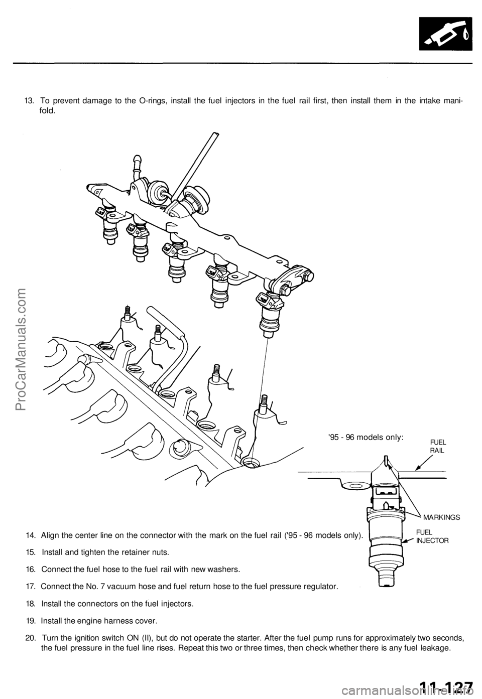
13. To prevent damage to the O-rings, install the fuel injectors in the fuel rail first, then install them in the intake mani-
fold.
'95 - 96 models only:
14. Align the center line on the connector with the mark on the fuel rail ('95 - 96 models only).
15. Install and tighten the retainer nuts.
16. Connect the fuel hose to the fuel rail with new washers.
17. Connect the No. 7 vacuum hose and fuel return hose to the fuel pressure regulator.
18. Install the connectors on the fuel injectors.
19. Install the engine harness cover.
20. Turn the ignition switch ON (II), but do not operate the starter. After the fuel pump runs for approximately two seconds,
the fuel pressure in the fuel line rises. Repeat this two or three times, then check whether there is any fuel leakage.
FUEL
INJECTOR
MARKINGS
FUEL
RAILProCarManuals.com
Page 908 of 1771
Fuel Suppl y Syste m
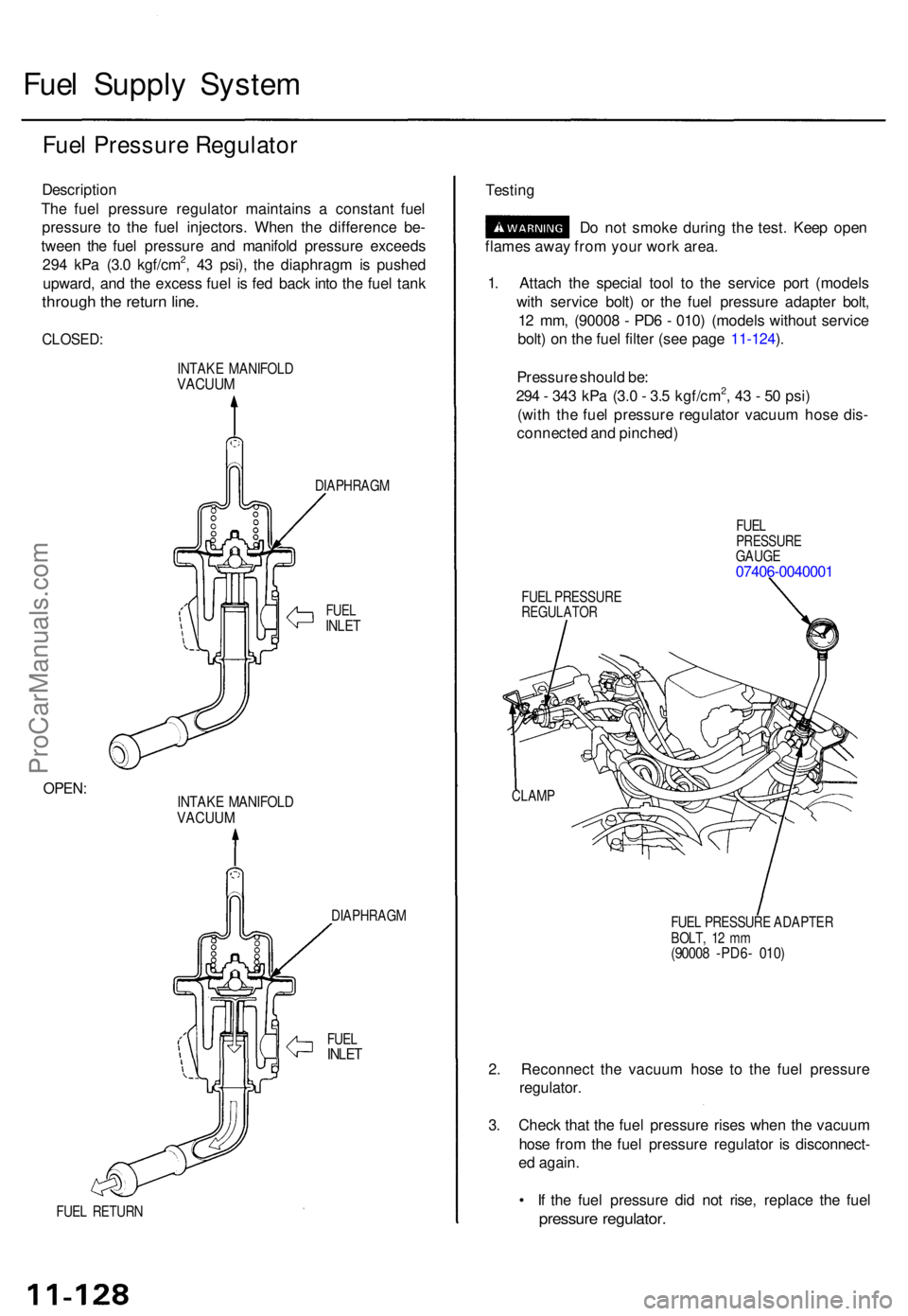
Fuel Pressur e Regulato r
Descriptio n
Th e fue l pressur e regulato r maintain s a constan t fue l
pressur e t o th e fue l injectors . Whe n th e differenc e be -
twee n th e fue l pressur e an d manifol d pressur e exceed s
29 4 kP a (3. 0 kgf/cm
2, 4 3 psi) , th e diaphrag m is pushe d
upward , an d th e exces s fue l i s fe d bac k int o th e fue l tan k
throug h th e retur n line .
CLOSED :
INTAKE MANIFOL DVACUUM
DIAPHRAG M
FUELINLE T
OPEN :INTAK E MANIFOL DVACUUM
FUEL RETUR N DIAPHRAG
M
FUE L
INLE T
Testin g
Do no t smok e durin g th e test . Kee p ope n
flame s awa y fro m you r wor k area .
1 . Attac h th e specia l too l t o th e servic e por t (model s
wit h servic e bolt ) o r th e fue l pressur e adapte r bolt ,
1 2 mm , (9000 8 - PD 6 - 010 ) (model s withou t servic e
bolt ) o n th e fue l filte r (se e pag e 11-124 ).
Pressur e shoul d be :
29 4 - 34 3 kP a (3. 0 - 3. 5 kgf/cm
2, 4 3 - 5 0 psi )
(wit h th e fue l pressur e regulato r vacuu m hos e dis -
connecte d an d pinched )
FUELPRESSUR EGAUGE07406-004000 1
FUEL PRESSUR EREGULATO R
FUEL PRESSUR E ADAPTE R
BOLT , 1 2 m m
(9000 8 -PD6 - 010 )
2. Reconnec t th e vacuu m hos e t o th e fue l pressur e
regulator .
3 . Chec k tha t th e fue l pressur e rise s whe n th e vacuu m
hos e fro m th e fue l pressur e regulato r i s disconnect -
e d again .
• I f th e fue l pressur e di d no t rise , replac e th e fue l
pressur e regulator .
CLAMP
ProCarManuals.com
Page 910 of 1771
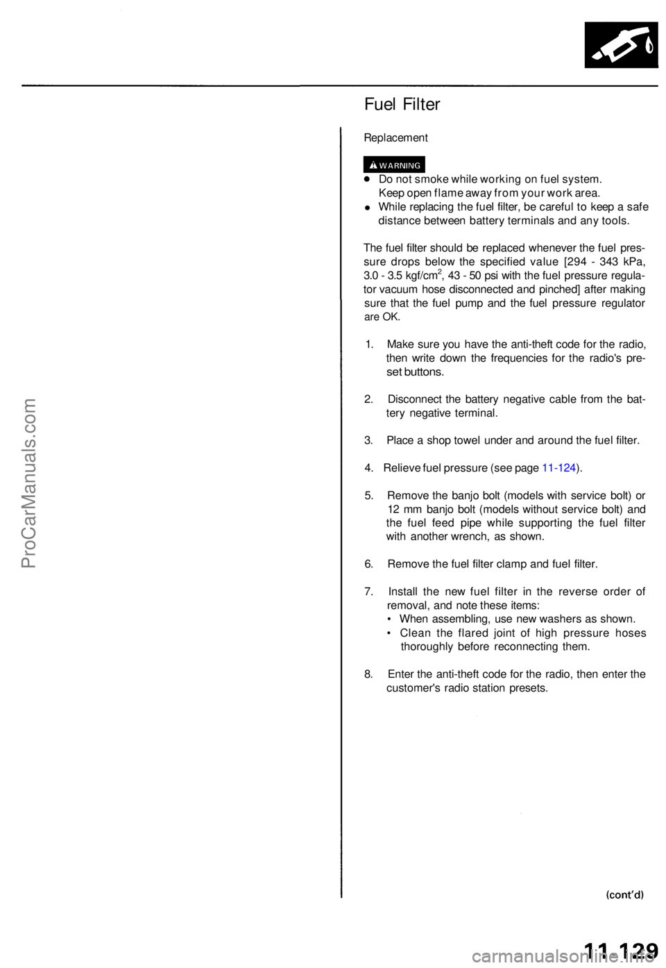
Fuel Filte r
Replacemen t
Do no t smok e whil e workin g o n fue l system .
Kee p ope n flam e awa y fro m you r wor k area .
• Whil e replacin g th e fue l filter , b e carefu l t o kee p a saf e
distanc e betwee n batter y terminal s an d an y tools .
Th e fue l filte r shoul d b e replace d wheneve r th e fue l pres -
sur e drop s belo w th e specifie d valu e [29 4 - 34 3 kPa ,
3. 0 - 3. 5 kgf/cm
2, 4 3 - 5 0 ps i wit h th e fue l pressur e regula -
to r vacuu m hos e disconnecte d an d pinched ] afte r makin g
sur e tha t th e fue l pum p an d th e fue l pressur e regulato r
are OK .
1. Mak e sur e yo u hav e th e anti-thef t cod e fo r th e radio ,
the n writ e dow n th e frequencie s fo r th e radio' s pre -
set buttons .
2. Disconnec t th e batter y negativ e cabl e fro m th e bat -
ter y negativ e terminal .
3 . Plac e a sho p towe l unde r an d aroun d th e fue l filter .
4 . Reliev e fue l pressur e (se e pag e 11-124 ).
5 . Remov e th e banj o bol t (model s wit h servic e bolt ) o r
1 2 m m banj o bol t (model s withou t servic e bolt ) an d
th e fue l fee d pip e whil e supportin g th e fue l filte r
wit h anothe r wrench , a s shown .
6 . Remov e th e fue l filte r clam p an d fue l filter .
7 . Instal l th e ne w fue l filte r i n th e revers e orde r of
removal , an d not e thes e items :
• Whe n assembling , us e ne w washer s a s shown .
• Clea n th e flare d join t o f hig h pressur e hose s
thoroughl y befor e reconnectin g them .
8 . Ente r th e anti-thef t cod e fo r th e radio , the n ente r th e
customer' s radi o statio n presets .
ProCarManuals.com
Page 954 of 1771
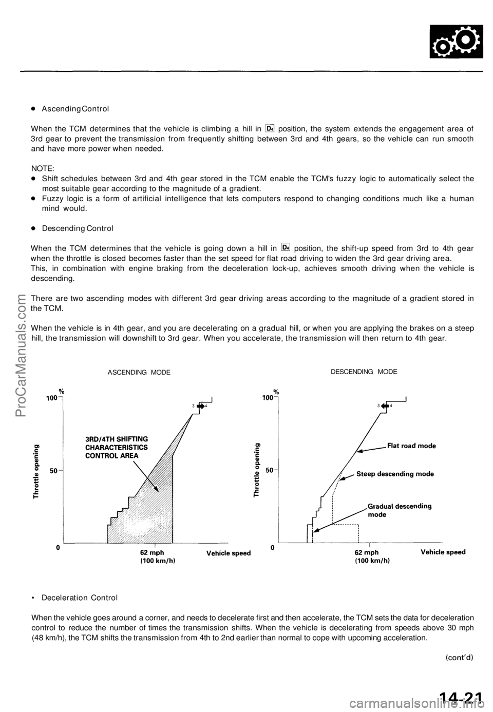
Ascending Control
When the TCM determines that the vehicle is climbing a hill in position, the system extends the engagement area of
3rd gear to prevent the transmission from frequently shifting between 3rd and 4th gears, so the vehicle can run smooth
and have more power when needed.
NOTE:
Shift schedules between 3rd and 4th gear stored in the TCM enable the TCM's fuzzy logic to automatically select the
most suitable gear according to the magnitude of a gradient.
Fuzzy logic is a form of artificial intelligence that lets computers respond to changing conditions much like a human
mind would.
Descending Control
When the TCM determines that the vehicle is going down a hill in position, the shift-up speed from 3rd to 4th gear
when the throttle is closed becomes faster than the set speed for flat road driving to widen the 3rd gear driving area.
This, in combination with engine braking from the deceleration lock-up, achieves smooth driving when the vehicle is
descending.
There are two ascending modes with different 3rd gear driving areas according to the magnitude of a gradient stored in
the
TCM.
When the vehicle is in 4th gear, and you are decelerating on a gradual hill, or when you are applying the brakes on a steep
hill, the transmission will downshift to 3rd gear. When you accelerate, the transmission will then return to 4th gear.
ASCENDING MODE
DESCENDING MODE
• Deceleration Control
When the vehicle goes around a corner, and needs to decelerate first and then accelerate, the TCM sets the data for deceleration
control to reduce the number of times the transmission shifts. When the vehicle is decelerating from speeds above 30 mph
(48 km/h), the TCM shifts the transmission from 4th to 2nd earlier than normal to cope with upcoming acceleration.ProCarManuals.com
Page 980 of 1771
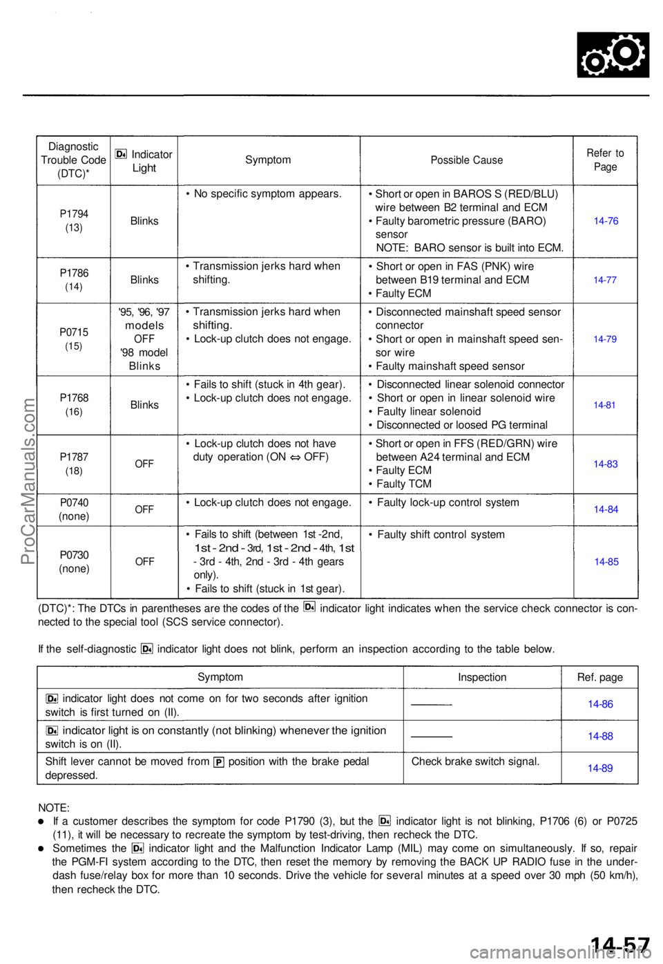
Diagnostic
Troubl e Cod e
(DTC) *
P1794
(13)
P178 6
(14)
P071 5
(15)
P176 8
(16)
P178 7
(18)
P074 0
(none )
P0730
(none )
Indicato r
Light
Blink s
Blinks
'95, '96 , '97
model s
OFF
'98 mode l
Blink s
Blinks
OFF
OF F
OFF
Sympto m
• N o specifi c sympto m appears .
• Transmissio n jerk s har d whe n
shifting .
• Transmissio n jerk s har d whe n
shifting .
• Lock-u p clutc h doe s no t engage .
• Fail s t o shif t (stuc k in 4t h gear) .
• Lock-u p clutc h doe s no t engage .
• Lock-u p clutc h doe s no t hav e
duty operatio n (O N OFF )
• Lock-u p clutc h doe s no t engage .
• Fail s t o shif t (betwee n 1s t -2nd,
1s t - 2n d - 3rd , 1st - 2nd - 4th , 1st
- 3r d - 4th , 2n d - 3r d - 4t h gear s
only) .
• Fail s t o shif t (stuc k in 1s t gear) .
Possibl e Caus e
• Shor t o r ope n in BARO S S (RED/BLU )
wir e betwee n B 2 termina l an d EC M
• Fault y barometri c pressur e (BARO )
sensor
NOTE : BAR O senso r i s buil t int o ECM .
• Shor t o r ope n in FA S (PNK ) wir e
betwee n B1 9 termina l an d EC M
• Fault y EC M
• Disconnecte d mainshaf t spee d senso r
connecto r
• Shor t o r ope n in mainshaf t spee d sen -
so r wir e
• Fault y mainshaf t spee d senso r
• Disconnecte d linea r solenoi d connecto r
• Shor t o r ope n in linea r solenoi d wir e
• Fault y linea r solenoi d
• Disconnecte d o r loose d P G termina l
• Shor t o r ope n in FF S (RED/GRN ) wir e
betwee n A2 4 termina l an d EC M
• Fault y EC M
• Fault y TC M
• Fault y lock-u p contro l syste m
• Fault y shif t contro l syste m
Refer t o
Pag e
14-7 6
14-77
14-7 9
14-8 1
14-8 3
14-8 4
14-8 5
(DTC)* : Th e DTC s i n parenthese s ar e th e code s o f th e indicato r ligh t indicate s whe n th e servic e chec k connecto r i s con -
necte d t o th e specia l too l (SC S servic e connector) .
If th e self-diagnosti c indicato r ligh t doe s no t blink , perfor m a n inspectio n accordin g t o th e tabl e below .
Sympto m
indicator ligh t doe s no t com e o n fo r tw o second s afte r ignitio n
switc h i s firs t turne d o n (II) .
indicato r ligh t i s o n constantl y (no t blinking ) wheneve r th e ignitio n
switch i s o n (II) .
Shif t leve r canno t b e move d fro m positio n wit h th e brak e peda l
depressed . Inspectio
n
Chec k brak e switc h signal . Ref
. pag e
14-86
14-8 8
14-8 9
NOTE :
If a custome r describe s th e sympto m fo r cod e P179 0 (3) , bu t th e indicato r ligh t i s no t blinking , P170 6 (6 ) o r P072 5
(11) , i t wil l b e necessar y t o recreat e th e sympto m b y test-driving , the n rechec k th e DTC .
Sometime s th e indicato r ligh t an d th e Malfunctio n Indicato r Lam p (MIL ) ma y com e o n simultaneously . I f so , repai r
th e PGM-F I syste m accordin g t o th e DTC , the n rese t th e memor y b y removin g th e BAC K U P RADI O fus e i n th e under -
das h fuse/rela y bo x fo r mor e tha n 1 0 seconds . Driv e th e vehicl e fo r severa l minute s a t a spee d ove r 3 0 mp h (5 0 km/h) ,
the n rechec k th e DTC .
ProCarManuals.com
Page 1258 of 1771
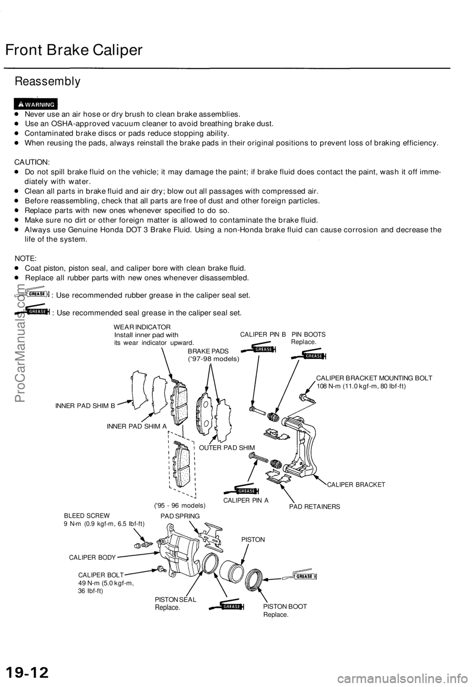
Front Brake Caliper
Reassembly
Never use an air hose or dry brush to clean brake assemblies.
Use an OSHA-approved vacuum cleaner to avoid breathing brake dust.
Contaminated brake discs or pads reduce stopping ability.
When reusing the pads, always reinstall the brake pads in their original positions to prevent loss of braking efficiency.
CAUTION:
Do not spill brake fluid on the vehicle; it may damage the paint; if brake fluid does contact the paint, wash it off imme-
diately with water.
Clean all parts in brake fluid and air dry; blow out all passages with compressed air.
Before reassembling, check that all parts are free of dust and other foreign particles.
Replace parts with new ones whenever specified to do so.
Make sure no dirt or other foreign matter is allowed to contaminate the brake fluid.
Always use Genuine Honda DOT 3 Brake Fluid. Using a non-Honda brake fluid can cause corrosion and decrease the
life of the system.
NOTE:
Coat piston, piston seal, and caliper bore with clean brake fluid.
Replace all rubber parts with new ones whenever disassembled.
: Use recommended rubber grease in the caliper seal set.
: Use recommended seal grease in the caliper seal set.
WEAR INDICATOR
Install inner pad with
its wear indicator upward.
BRAKE PADS
('97-98 models)
CALIPER PIN B PIN BOOTS
Replace.
INNER PAD SHIM B
CALIPER BRACKET MOUNTING BOLT
108 N-m (11.0 kgf-m, 80 Ibf-ft)
INNER PAD SHIM A
BLEED SCREW
9 N-m (0.9 kgf-m, 6.5 Ibf-ft)
CALIPER BODY
CALIPER BOLT
49 N-m (5.0 kgf-m,
36 Ibf-ft)
('95 - 96 models)
PAD SPRING
CALIPER BRACKET
PAD RETAINERS
PISTON
PISTON SEAL
Replace.
PISTON BOOT
Replace.
OUTER PAD SHIM
CALIPER PIN AProCarManuals.com