1995 ACURA TL ECO mode
[x] Cancel search: ECO modePage 1696 of 1771
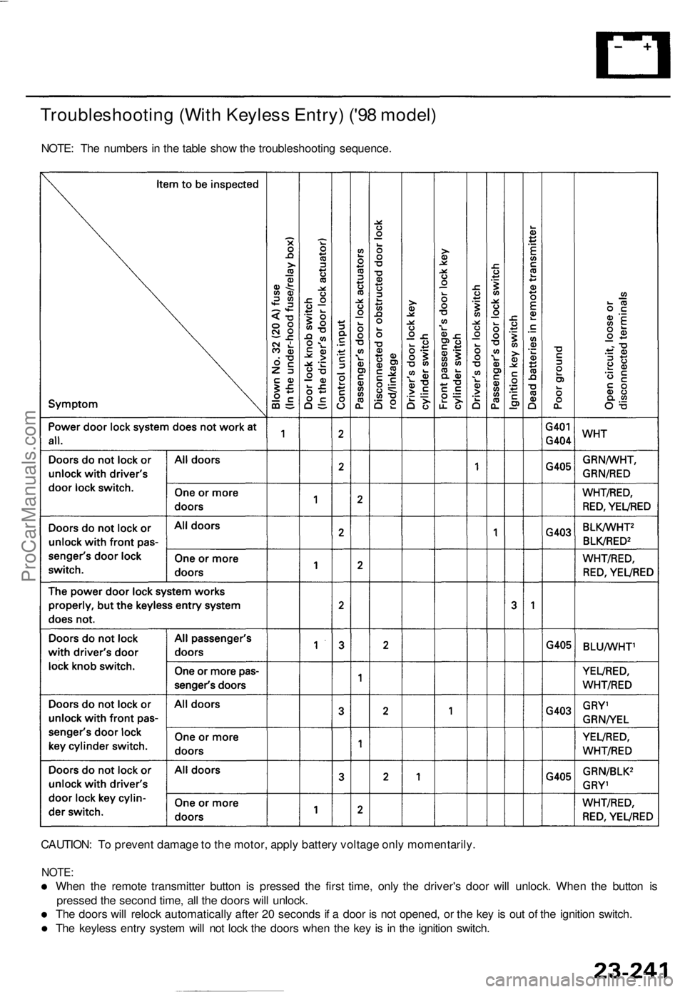
Troubleshooting (With Keyless Entry) ('98 model)
NOTE: The numbers in the table show the troubleshooting sequence.
CAUTION: To prevent damage to the motor, apply battery voltage only momentarily.
NOTE:
When the remote transmitter button is pressed the first time, only the driver's door will unlock. When the button is
pressed the second time, all the doors will unlock.
The doors will relock automatically after 20 seconds if a door is not opened, or the key is out of the ignition switch.
The keyless entry system will not lock the doors when the key is in the ignition switch.ProCarManuals.com
Page 1704 of 1771
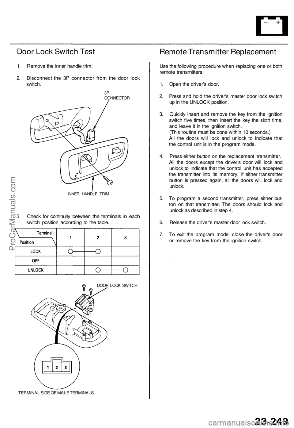
Door Lock Switch Test
1. Remove the inner handle trim.
2. Disconnect the 3P connector from the door lock
switch.
3P
CONNECTOR
INNER HANDLE TRIM
3. Check for continuity between the terminals in each
switch position according to the table.
DOOR LOCK SWITCH
TERMINAL SIDE OF MALE TERMINALS
Remote Transmitter Replacement
Use the following procedure when replacing one or both
remote transmitters:
1. Open the driver's door.
2. Press and hold the driver's master door lock switch
up in the UNLOCK position.
3. Quickly insert and remove the key from the ignition
switch five times, then insert the key the sixth time,
and leave it in the ignition switch.
(This routine must be done within 10 seconds.)
All the doors will lock and unlock to indicate that
the control unit is in the program mode.
4. Press either button on the replacement transmitter.
All the doors except the driver's door will lock and
unlock to indicate that the control unit has accepted
the transmitter into its memory. If either transmitter
button is pressed again, all the doors will lock and
unlock.
5. To program a second transmitter, press either but-
ton on that transmitter. The doors should lock and
unlock as described in step 4.
6. Release the driver's master door lock switch.
7. To exit the program mode, close the driver's door
or remove the key from the ignition switch.ProCarManuals.com
Page 1741 of 1771
Precautions/Procedures
SRS Uni t Precaution s
• Tak e extr a car e whe n paintin g o r doin g bod y wor k i n
th e are a belo w th e dashboard . Avoi d direc t exposur e
of th e SR S uni t o r wirin g t o hea t guns , welding , o r
sprayin g equipment .
• Disconnec t th e airba g connector(s ) befor e discon -
nectin g SR S harnes s connector s (se e pag e 24-12 ). O n
'95-9 6 models , connec t th e shor t connecto r t o th e
fron t passenger' s airba g connector .
• Afte r an y degre e o f fronta l bod y damage , o r afte r a
collisio n withou t airba g deployment , inspec t th e SR S
uni t fo r physica l damage . I f i t i s dented , cracked , o r
deformed , replac e it .
Inspectio n Afte r Deploymen t
After a collisio n i n whic h th e airbag s wer e deployed ,
replac e th e SR S unit , an d inspec t th e following :
1 . Inspec t al l th e SR S wir e harnesses . Replace , don' t
repair , an y damage d harnesses .
2 . Inspec t th e cabl e ree l fo r hea t damage . I f ther e is an y
damage , replac e th e cabl e reel .
3 . Afte r th e vehicl e i s completel y repaired , tur n th e
ignitio n switc h on . I f th e SR S indicato r ligh t come s
o n fo r abou t si x second s an d the n goe s off , th e SR S
syste m is OK . I f th e indicato r ligh t doe s no t functio n
properly , g o t o SR S Troubleshooting .
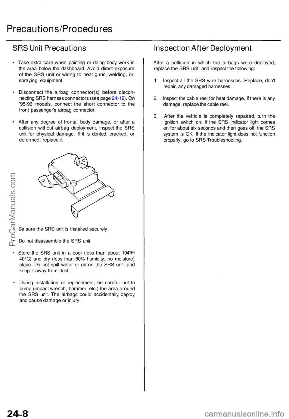
• B e sur e th e SR S uni t i s installe d securely .
• D o no t disassembl e th e SR S unit .
• Stor e th e SR S uni t i n a coo l (les s tha n abou t 104°F /
40°C ) an d dr y (les s tha n 80 % humidity , n o moisture )
place . D o no t spil l wate r o r oi l o n th e SR S unit , an d
kee p it awa y fro m dust .
• Durin g installatio n o r replacement , b e carefu l no t t o
bum p (impac t wrench , hammer , etc. ) th e are a aroun d
th e SR S unit . Th e airbag s coul d accidentall y deplo y
an d caus e damag e o r injury .
ProCarManuals.com
Page 1746 of 1771
Steering-related Precautions
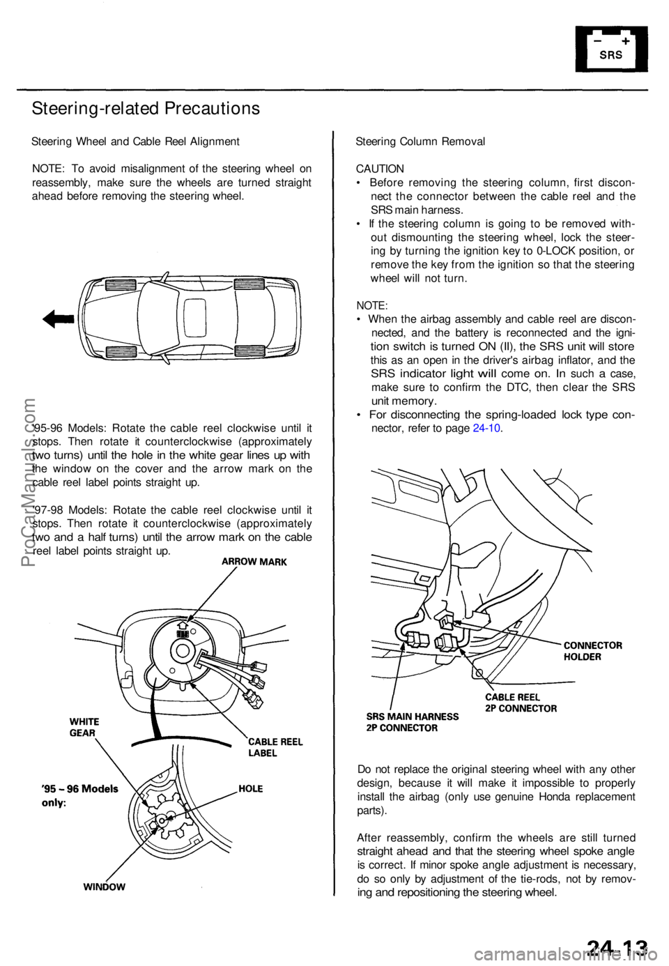
Steering Whee l an d Cabl e Ree l Alignmen t
NOTE : T o avoi d misalignmen t o f th e steerin g whee l o n
reassembly , mak e sur e th e wheel s ar e turne d straigh t
ahea d befor e removin g th e steerin g wheel .
'95-9 6 Models : Rotat e th e cabl e ree l clockwis e unti l i t
stops . The n rotat e i t counterclockwis e (approximatel y
two turns ) unti l th e hol e in th e whit e gea r line s u p wit h
the windo w o n th e cove r an d th e arro w mar k o n th e
cabl e ree l labe l point s straigh t up .
'97-9 8 Models : Rotat e th e cabl e ree l clockwis e unti l i t
stops . The n rotat e i t counterclockwis e (approximatel y
two an d a hal f turns ) unti l th e arro w mar k o n th e cabl e
reel labe l point s straigh t up . Steerin
g Colum n Remova l
CAUTIO N
• Befor e removin g th e steerin g column , firs t discon -
nec t th e connecto r betwee n th e cabl e ree l an d th e
SR S mai n harness .
• I f th e steerin g colum n i s goin g t o b e remove d with -
ou t dismountin g th e steerin g wheel , loc k th e steer -
in g b y turnin g th e ignitio n ke y to 0-LOC K position , o r
remov e th e ke y fro m th e ignitio n s o tha t th e steerin g
whee l wil l no t turn .
NOTE :
• Whe n th e airba g assembl y an d cabl e ree l ar e discon -
nected , an d th e batter y i s reconnecte d an d th e igni -
tion switc h is turne d O N (II) , th e SR S uni t wil l stor e
this a s a n ope n i n th e driver' s airba g inflator , an d th e
SR S indicato r light will com e on. I n suc h a case ,
mak e sur e t o confir m th e DTC , the n clea r th e SR S
unit memory .
• Fo r disconnectin g th e spring-loade d loc k typ e con -
nector , refe r t o pag e 24-10 .
D o no t replac e th e origina l steerin g whee l wit h an y othe r
design , becaus e i t wil l mak e i t impossibl e t o properly
instal l th e airba g (onl y us e genuin e Hond a replacemen t
parts) .
Afte r reassembly , confir m th e wheel s ar e stil l turne d
straight ahea d an d tha t th e steerin g whee l spok e angl e
is correct . I f mino r spok e angl e adjustment is necessary ,
d o s o onl y b y adjustmen t o f th e tie-rods , no t b y remov -
ing an d repositionin g th e steerin g wheel .
ProCarManuals.com
Page 1747 of 1771
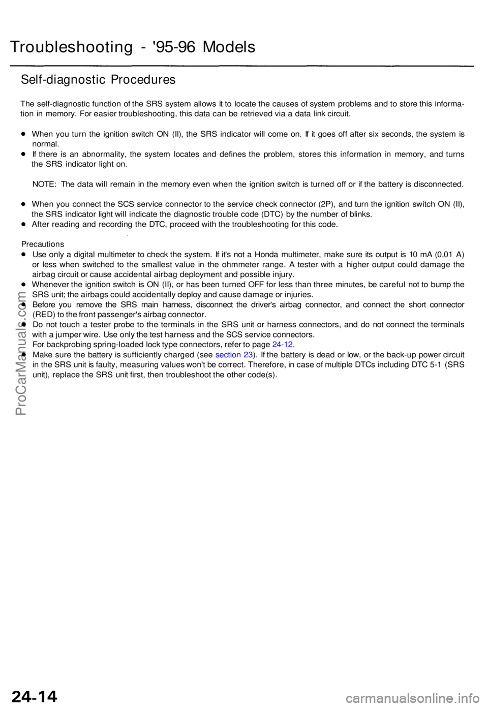
Troubleshooting - '95-9 6 Model s
Self-diagnosti c Procedure s
The self-diagnosti c functio n o f th e SR S syste m allow s i t t o locat e th e cause s o f syste m problem s an d t o stor e thi s informa -
tio n in memory . Fo r easie r troubleshooting, this dat a ca n b e retrieve d vi a a dat a lin k circuit .
Whe n yo u tur n th e ignitio n switc h O N (II) , th e SR S indicator will com e on . I f i t goe s of f afte r si x seconds , th e syste m is
normal .
I f ther e i s a n abnormality , th e syste m locate s an d define s th e problem , store s thi s informatio n i n memory , an d turn s
th e SR S indicato r ligh t on .
NOTE : Th e dat a wil l remai n i n th e memor y eve n whe n th e ignitio n switc h is turne d of f o r i f th e batter y i s disconnected .
Whe n yo u connec t th e SC S servic e connecto r t o th e servic e chec k connecto r (2P) , an d tur n th e ignitio n switc h O N (II) ,
th e SR S indicato r ligh t wil l indicat e th e diagnosti c troubl e cod e (DTC ) b y th e numbe r o f blinks .
Afte r readin g an d recordin g th e DTC , procee d wit h th e troubleshootin g fo r thi s code .
Precaution s
Use onl y a digita l multimete r t o chec k th e system . I f it' s no t a Hond a multimeter , mak e sur e it s outpu t i s 1 0 m A (0.0 1 A )
o r les s whe n switche d t o th e smalles t valu e i n th e ohmmete r range . A teste r wit h a highe r outpu t coul d damag e th e
airba g circui t o r caus e accidenta l airba g deploymen t an d possibl e injury .
Wheneve r th e ignitio n switc h is O N (II) , o r ha s bee n turne d OF F fo r les s tha n thre e minutes , b e carefu l no t t o bum p th e
SR S unit ; th e airbag s coul d accidentall y deplo y an d caus e damag e o r injuries .
Befor e yo u remov e th e SR S mai n harness , disconnec t th e driver' s airba g connector , an d connec t th e shor t connecto r
(RED ) t o th e fron t passenger' s airba g connector .
D o no t touc h a teste r prob e t o th e terminal s i n th e SR S uni t o r harnes s connectors , an d d o no t connec t th e terminal s
wit h a jumpe r wire . Us e onl y th e tes t harnes s an d th e SC S servic e connectors .
Fo r backprobin g spring-loade d loc k typ e connectors , refe r t o pag e 24-12 .
Mak e sur e th e batter y i s sufficientl y charge d (se e sectio n 23 ). I f th e batter y i s dea d o r low , o r th e back-u p powe r circui t
i n th e SR S uni t i s faulty , measurin g value s won' t b e correct . Therefore , i n cas e o f multipl e DTC s includin g DT C 5- 1 (SR S
unit) , replac e th e SR S uni t first , the n troubleshoo t th e othe r code(s) .
ProCarManuals.com
Page 1750 of 1771
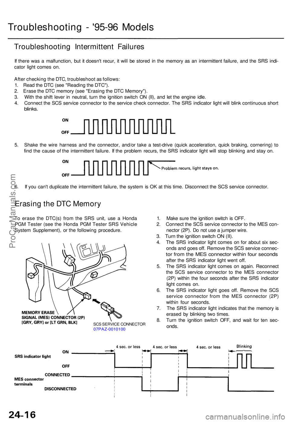
SCS SERVIC E CONNECTO R07PAZ-001010 0
Troubleshootin g - '95-9 6 Model s
Troubleshootin g Intermitten t Failure s
If ther e wa s a malfunction , bu t i t doesn' t recur , i t wil l b e store d i n th e memor y a s a n intermitten t failure, and th e SR S indi -
cato r ligh t come s on .
Afte r checkin g th e DTC , troubleshoo t a s follows :
1 . Rea d th e DT C (se e "Readin g th e DTC") .
2 . Eras e th e DT C memor y (se e "Erasin g th e DT C Memory") .
3 . Wit h th e shif t leve r i n neutral , tur n th e ignitio n switc h O N (II) , an d le t th e engin e idle .
4 . Connec t th e SC S servic e connecto r t o th e servic e chec k connector . Th e SR S indicato r ligh t wil l blin k continuou s shor t
blinks .
5. Shak e th e wir e harnes s an d th e connector , and/o r tak e a test-driv e (quic k acceleration , quic k braking , cornering ) t o
fin d th e caus e o f th e intermitten t failure . I f th e proble m recurs , th e SR S indicato r ligh t wil l sto p blinkin g an d sta y on .
6 . I f yo u can' t duplicat e th e intermitten t failure , th e syste m is O K a t thi s time . Disconnec t th e SC S servic e connector .
Erasing th e DT C Memor y
To eras e th e DTC(s ) fro m th e SR S unit , us e a Hond a
PG M Teste r (se e th e Hond a PG M Teste r SR S Vehicl e
Syste m Supplement) , o r th e followin g procedure . 1
. Mak e sur e th e ignitio n switc h is OFF .
2 . Connec t th e SC S servic e connecto r t o th e ME S con -
necto r (2P) . D o no t us e a jumpe r wire .
3. Tur n th e ignitio n switc h O N (II) .
4. Th e SR S indicato r ligh t come s o n fo r abou t si x sec -
ond s an d goe s off . Remov e th e SC S servic e connec -
tor fro m th e ME S connecto r withi n fou r second s
after th e SR S indicato r ligh t wen t off .
5 . Th e SR S indicato r ligh t come s o n again . Reconnec t
th e SC S servic e connecto r t o th e ME S connecto r
(2P ) withi n th e fou r second s afte r th e SR S indicato r
ligh t come s on .
6 . Th e SR S indicato r ligh t goe s off . Remov e th e SC S
servic e connecto r fro m th e ME S connecto r (2P )
withi n fou r seconds .
7 . Th e SR S indicato r ligh t indicate s tha t th e memor y i s
erase d b y blinkin g tw o times .
8 . Tur n th e ignitio n switc h OFF , an d wai t fo r te n sec -
onds .
ProCarManuals.com
Page 1753 of 1771
Troubleshooting - '97-9 8 Model s
Self-diagnosti c Procedure s
The self-diagnosti c functio n o f th e SR S syste m allow s it t o locat e th e cause s o f syste m problem s an d t o stor e thi s informa -
tio n in memory . Fo r easie r troubleshooting , thi s dat a ca n b e retrieve d vi a a dat a lin k circuit .
Whe n yo u tur n th e ignitio n switc h O N (II) , th e SR S indicato r wil l com e on . I f i t goe s of f afte r si x seconds , th e syste m is
normal .
I f ther e i s a n abnormality , th e syste m locate s an d define s th e problem , store s thi s informatio n i n memory , an d turn s
th e SR S indicato r ligh t on .
NOTE : Th e dat a wil l remai n in th e memor y eve n whe n th e ignitio n switc h i s turne d of f o r i f th e batter y is disconnected .
Whe n yo u connec t th e SC S servic e connecto r t o th e servic e chec k connecto r (2P) , an d tur n th e ignitio n switc h O N (II) ,
th e SR S indicato r ligh t wil l indicat e th e diagnosti c troubl e cod e (DTC ) b y th e numbe r o f blinks .
Afte r readin g an d recordin g th e DTC , procee d wit h th e troubleshootin g fo r thi s code .
Precaution s
Use onl y a digita l multimete r t o chec k th e system . I f it' s no t a Hond a multimeter , mak e sur e it s outpu t i s 1 0 m A (0.0 1 A )
o r les s whe n switche d t o th e smalles t valu e i n th e ohmmete r range . A teste r wit h a highe r outpu t coul d damag e th e
airba g circui t o r caus e accidenta l airba g deploymen t an d possibl e injury .
Whenever the ignitio n switc h is O N (II) , o r ha s bee n turne d OF F fo r les s tha n thre e minutes , b e carefu l no t t o bum p th e
SR S unit ; th e airbag s coul d accidentall y deplo y an d caus e damag e o r injuries .
Befor e yo u remov e th e SR S mai n harness , disconnec t th e driver' s airba g connector, and th e fron t passenger' s airba g
connector .
Mak e sur e th e batter y i s sufficientl y charge d (se e sectio n 23 ). I f th e batter y i s dea d o r low , measurin g value s won' t b e
correct .
D o no t touc h a teste r prob e t o th e terminal s i n th e SR S uni t o r harnes s connectors , an d d o no t connec t th e terminal s
wit h a jumpe r wire . Us e onl y th e tes t harnes s an d th e SC S servic e connectors .
Fo r backprobin g spring-loade d loc k typ e connectors , refe r t o pag e 24-11 .
ProCarManuals.com
Page 1755 of 1771
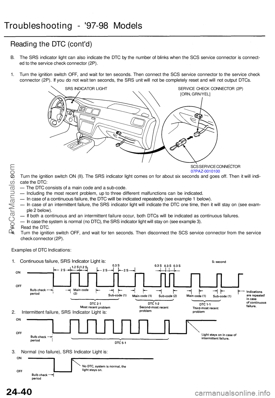
Troubleshooting - '97-9 8 Model s
Reading th e DT C (cont'd )
B. Th e SR S indicato r ligh t ca n als o indicat e th e DT C b y th e numbe r o f blink s whe n th e SC S servic e connecto r i s connect -
e d to th e servic e chec k connecto r (2P) .
1 . Tur n th e ignitio n switc h OFF , an d wai t fo r te n seconds . The n connec t th e SC S servic e connecto r t o th e servic e chec k
connecto r (2P) . I f yo u d o no t wai t te n seconds , th e SR S uni t wil l no t b e completel y rese t an d wil l no t outpu t DTCs .
SRS INDICATO R LIGH T SERVIC E CHEC K CONNECTO R (2P )
[ORN , GRN/YEL ]
SCS SERVIC E CONNECTO R07PAZ-001010 0
2. Tur n th e ignitio n switc h O N (II) . Th e SR S indicato r ligh t come s o n fo r abou t si x second s an d goe s off . The n it wil l indi -
cat e th e DTC :
Th e DT C consist s o f a mai n cod e an d a sub-code .
Includin g th e mos t recen t problem , u p t o thre e differen t malfunction s ca n b e indicated .
In cas e of a continuou s failure, the DT C will be indicate d repeatedl y (see exampl e 1 below).
In cas e o f a n intermitten t failure , th e SR S indicato r ligh t wil l indicat e th e DT C on e time , the n it wil l sta y o n (se e exam -
pl e 2 below) .
I f bot h a continuou s an d a n intermitten t failur e occur , bot h DTC s wil l b e indicate d a s continuou s failures .
I n cas e th e syste m is norma l (n o DTC) , th e SR S indicato r ligh t wil l sta y o n (se e exampl e 3) .
3. Rea d th e DTC .
4. Tur n th e ignitio n switc h OFF , an d wai t fo r te n seconds . The n disconnec t th e SC S servic e connecto r fro m th e servic e
chec k connecto r (2P) .
Example s o f DT C Indications :
1. Continuou s failure , SR S Indicato r Ligh t is :
2. Intermitten t failure , SR S Indicato r Ligh t is :
3 . Norma l (n o failure) , SR S Indicato r Ligh t is :
ProCarManuals.com