1995 ACURA TL ECO mode
[x] Cancel search: ECO modePage 1261 of 1771
Pushrod Clearanc e Adjustmen t
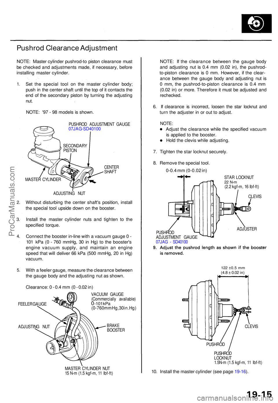
NOTE: Maste r cylinde r pushrod-t o pisto n clearanc e mus t
b e checke d an d adjustment s made , i f necessary , befor e
installin g maste r cylinder .
1.
2 .
3.
4 .
5 .
Se t th e specia l too l o n th e maste r cylinde r body ;
pus h in th e cente r shaf t unti l th e to p o f i t contact s th e
en d o f th e secondar y pisto n b y turnin g th e adjustin g
nut.
NOTE : '9 7 - 9 8 model s i s shown .
PUSHRO D ADJUSTMEN T GAUG E07JAG-SD4010 0
CENTERSHAFT
ADJUSTIN G NU T
Withou t disturbin g th e cente r shaft' s position , instal l
th e specia l too l upsid e dow n o n th e booster .
Instal l th e maste r cylinde r nut s an d tighte n t o th e
specifie d torque .
Connec t th e booste r in-lin e wit h a vacuu m gaug e 0 -
10 1 kP a ( 0 - 76 0 mmHg , 3 0 in Hg ) t o th e booster' s
engin e vacuu m supply , an d maintai n a n engin e
spee d tha t wil l delive r 6 6 kP a (50 0 mmHg , 2 0 in Hg )
vacuum .
With a feele r gauge , measur e th e clearanc e betwee n
th e gaug e bod y an d th e adjustin g nu t a s shown .
Clearance : 0 - 0. 4 m m (0 - 0.0 2 in )
FEELE R GAUG E
ADJUSTIN G NU T VACUU
M GAUG E
(Commerciall y available )0 -101 kPa(0-760mmHg,30in.Hg )
BRAKEBOOSTE R
MASTER CYLINDE R NU T
1 5 N- m (1. 5 kgf-m , 1 1 Ibf-ft )
NOTE : I f th e clearanc e betwee n th e gaug e bod y
an d adjustin g nu t i s 0. 4 m m (0.0 2 in) , th e pushrod -
to-pisto n clearanc e i s 0 mm . However , i f th e clear -
anc e betwee n th e gaug e bod y an d adjustin g nu t i s
0 mm , th e pushrod-to-pisto n clearanc e i s 0. 4 m m
(0.0 2 in ) o r more . Therefor e it mus t b e adjuste d an d
rechecked .
6. I f clearanc e i s incorrect , loose n th e sta r locknu t an d
tur n th e adjuste r i n o r ou t t o adjust .
NOTE:
Adjust th e clearanc e whil e th e specifie d vacuu m
i s applie d t o th e booster .
Hol d th e clevi s whil e adjusting .
7 . Tighte n th e sta r locknu t securely .
8 . Remov e th e specia l tool .
0-0. 4 m m (0-0.0 2 in )
STA R LOCKNU T22 N- m(2.2 kgf-m , 1 6 Ibf-ft )
PUSHRO D
LOCKNU T
1.5N- m (1. 5 kgf-m , 1 1 Ibf-ft )
10. Instal l th e maste r cylinde r (se e pag e 19-16 ).
MASTE R CYLINDE RSECONDAR
Y
PISTO N
CLEVIS
ADJUSTE R
PUSHRO D
ADJUSTMEN T GAUG E
07JA G - SD4010 0
122 ±0. 5 mm(4.8 ± 0.0 2 in)
CLEVI S
PUSHRO D
ProCarManuals.com
Page 1332 of 1771
Diagnostic Troubl e Cod e (DTC )
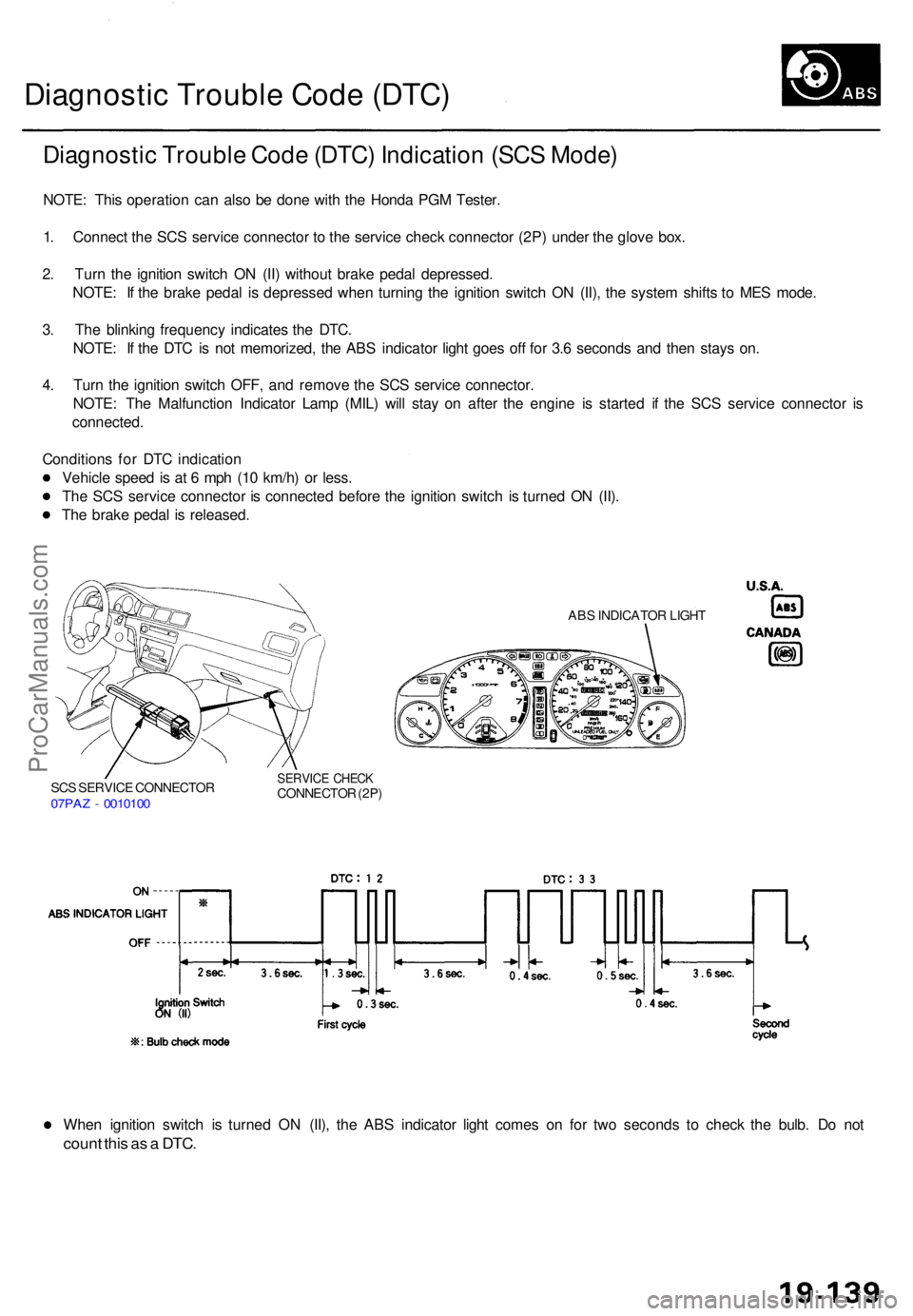
Diagnosti c Troubl e Cod e (DTC ) Indicatio n (SC S Mode )
NOTE: Thi s operatio n ca n als o b e don e wit h th e Hond a PG M Tester .
1 . Connec t th e SC S servic e connecto r t o th e servic e chec k connecto r (2P ) unde r th e glov e box .
2 . Tur n th e ignitio n switc h O N (II ) withou t brak e peda l depressed .
NOTE : I f th e brak e peda l i s depresse d whe n turnin g th e ignitio n switc h O N (II) , th e syste m shift s t o ME S mode .
3 . Th e blinkin g frequenc y indicate s th e DTC .
NOTE : I f th e DT C is no t memorized , th e AB S indicato r ligh t goe s of f fo r 3. 6 second s an d the n stay s on .
4 . Tur n th e ignitio n switc h OFF , an d remov e th e SC S servic e connector .
NOTE : Th e Malfunctio n Indicato r Lam p (MIL ) wil l sta y o n afte r th e engin e i s starte d i f th e SC S servic e connecto r i s
connected .
Condition s fo r DT C indicatio n
Vehicl e spee d is a t 6 mp h (1 0 km/h ) o r less .
Th e SC S servic e connecto r i s connecte d befor e th e ignitio n switc h i s turne d O N (II) .
Th e brak e peda l i s released .
SCS SERVIC E CONNECTO R07PAZ - 001010 0
SERVIC E CHEC KCONNECTO R (2P )
ABS INDICATO R LIGH T
When ignitio n switc h i s turne d O N (II) , th e AB S indicato r ligh t come s o n fo r tw o second s t o chec k th e bulb . D o no t
coun t thi s a s a DTC .
ProCarManuals.com
Page 1333 of 1771
Diagnostic Trouble Code (DTC)
DTC Erasure (MES Mode)
NOTE: This operation can also be done with the Honda PGM Tester.
1. Connect the SCS service connector to the service check connector (2P) under the glove box.
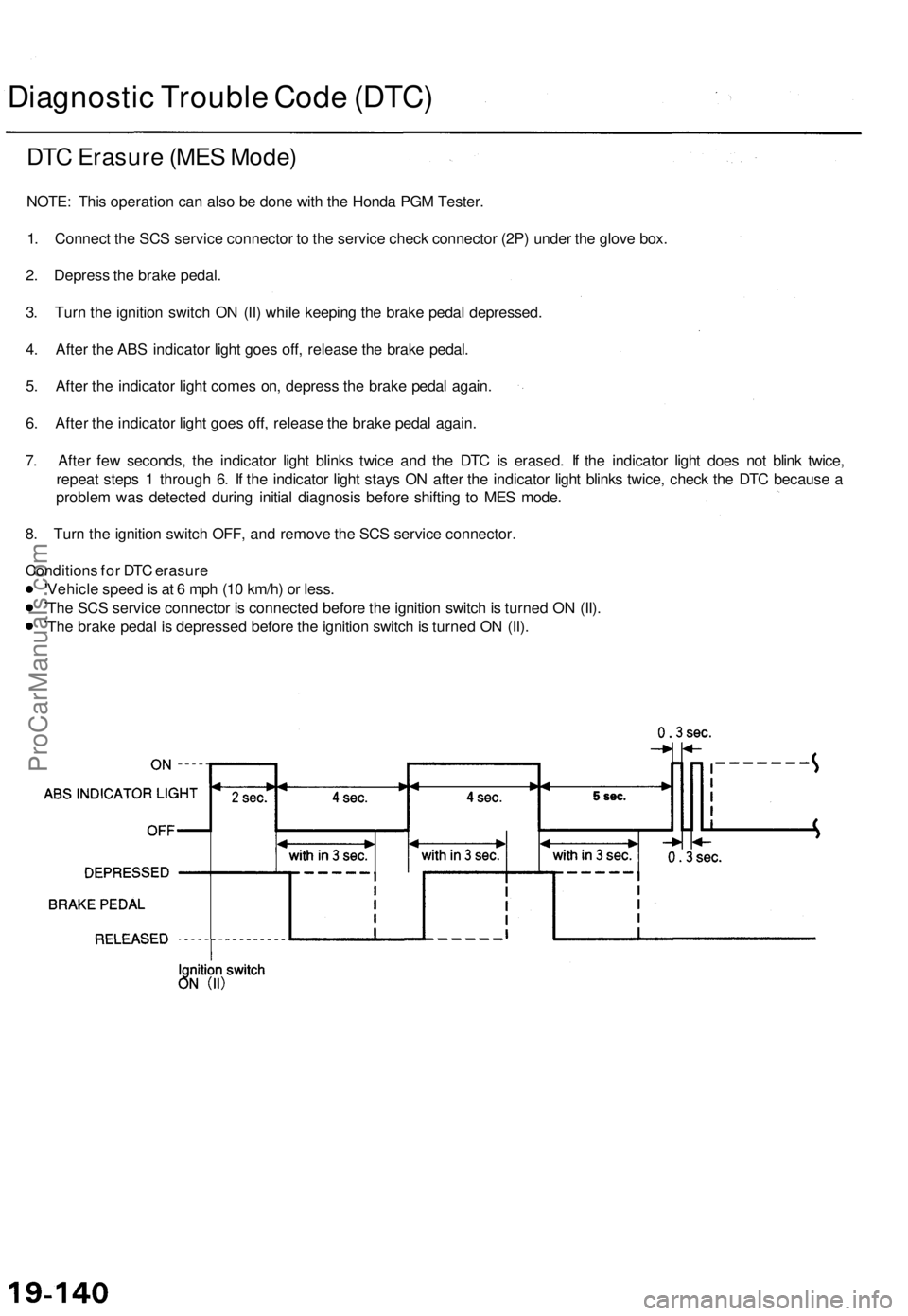
2. Depress the brake pedal.
3. Turn the ignition switch ON (II) while keeping the brake pedal depressed.
4. After the ABS indicator light goes off, release the brake pedal.
5. After the indicator light comes on, depress the brake pedal again.
6. After the indicator light goes off, release the brake pedal again.
7. After few seconds, the indicator light blinks twice and the DTC is erased. If the indicator light does not blink twice,
repeat steps 1 through 6. If the indicator light stays ON after the indicator light blinks twice, check the DTC because a
problem was detected during initial diagnosis before shifting to MES mode.
8. Turn the ignition switch OFF, and remove the SCS service connector.
Conditions for DTC erasure
Vehicle speed is at 6 mph (10 km/h) or less.
The SCS service connector is connected before the ignition switch is turned ON (II).
The brake pedal is depressed before the ignition switch is turned ON (II).ProCarManuals.com
Page 1538 of 1771
Five-step Troubleshooting
1. Verify The Complaint
Turn on all the components in the problem circuit to
verify the customer complaint. Note the symptoms.
Do not begin disassembly or testing until you have
narrowed down the problem area.
2. Analyze The Schematic
Look up the schematic for the problem circuit.
Determine how the circuit is supposed to work by
tracing the current paths from the power feed
through the circuit components to ground. If several
circuits fail at the same time, the fuse or ground is a
likely cause.
Based on the symptoms and your understanding of
the circuit operation, identify one or more possible
causes of the problem.
3. Isolate The Problem By Testing The Circuit
Make circuit tests to check the diagnosis you made
in step 2. Keep in mind that a logical, simple proce-
dure is the key to efficient troubleshooting. Test for
the most likely cause of failure first. Try to make
tests at points that are easily accessible.
4. Fix The Problem
Once the specific problem is identified, make the
repair. Be sure to use proper tools and safe proce-
dures.
5. Make Sure The Circuit Works
Turn on all components in the repaired circuit in all
modes to make sure you've fixed the entire prob-
lem. If the problem was a blown fuse, be sure to
test all of the circuits on the fuse. Make sure no new
problems turn up and the original problem does not
recur.
Wire Color Codes
The following abbreviations are used to identify wire
colors in the circuit schematics:
WHT .............................White
YEL ............................... Yellow
BLK .............................. Black
BLU
..............................
Blue
GRN ............................. Green
RED
..............................
Red
ORN ............................. Orange
PNK.............................. Pink
BRN .............................. Brown
GRY.............................. Gray
PUR .............................. Purple
LT BLU ......................... Light Blue
LT GRN ........................ Light Green
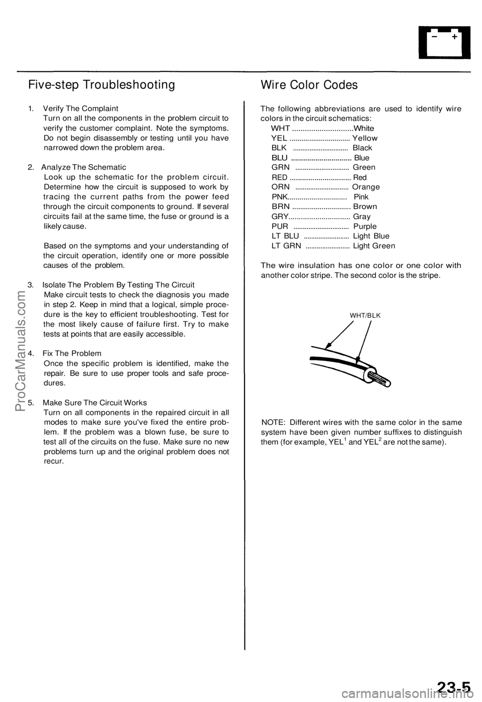
The wire insulation has one color or one color with
another color stripe. The second color is the stripe.
WHT/BLK
NOTE: Different wires with the same color in the same
system have been given number suffixes to distinguish
them (for example, YEL1 and YEL2 are not the same).ProCarManuals.com
Page 1550 of 1771
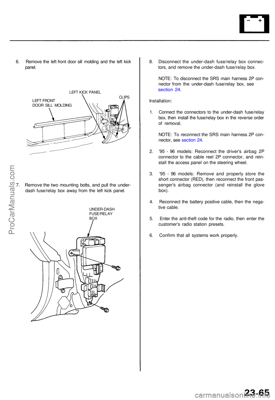
6. Remov e th e lef t fron t doo r sil l moldin g an d th e lef t kic k
panel .
LEFT KIC K PANE L
LEFT FRON TDOOR SIL L MOLDIN G
CLIPS
7. Remov e th e tw o mountin g bolts , an d pul l th e under -
dash fuse/rela y bo x awa y fro m th e lef t kic k panel .
UNDER-DAS HFUSE/RELAYBOX
8. Disconnec t th e under-das h fuse/rela y bo x connec -
tors , an d remov e th e under-das h fuse/rela y box .
NOTE : T o disconnec t th e SR S mai n harnes s 2 P con -
necto r fro m th e under-das h fuse/rela y box , se e
sectio n 24 .
Installation :
1 . Connec t th e connector s t o th e under-das h fuse/rela y
box , the n instal l th e fuse/rela y bo x in th e revers e orde r
o f removal .
NOTE : T o reconnec t th e SR S mai n harnes s 2 P con -
nector , se e sectio n 24 .
2 . '9 5 - 9 6 models : Reconnec t th e driver' s airba g 2 P
connecto r t o th e cabl e ree l 2 P connector , an d rein -
stal l th e acces s pane l o n th e steerin g wheel .
3 . '9 5 - 9 6 models : Remov e an d properl y stor e th e
shor t connecto r (RED) , the n reconnec t th e fron t pas -
senger' s airba g connecto r (an d reinstal l th e glov e
box).
4. Reconnec t th e batter y positiv e cable , the n th e nega -
tiv e cable .
5 . Ente r th e anti-thef t cod e fo r th e radio , the n ente r th e
customer' s radi o statio n presets .
6 . Confir m tha t al l system s wor k properly .
ProCarManuals.com
Page 1580 of 1771
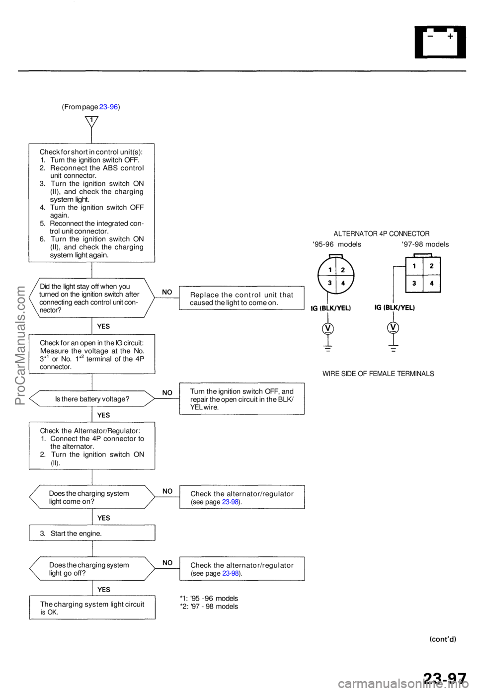
(From page 23-96 )
Chec k fo r shor t i n contro l unit(s) :
1 . Tur n th e ignitio n switc h OFF .
2 . Reconnec t th e AB S contro l
uni t connector .
3 . Tur n th e ignitio n switc h O N
(II) , an d chec k th e chargin g
system light .4. Tur n th e ignitio n switc h OF Fagain .5. Reconnec t th e integrate d con -trol uni t connector .6. Tur n th e ignitio n switc h O N
(II) , an d chec k th e chargin g
system ligh t again .
Did th e ligh t sta y of f whe n yo u
turne d o n th e ignitio n switc h afte r
connectin g eac h contro l uni t con -
nector ?
Check fo r a n ope n in th e IG circuit :
Measur e th e voltag e a t th e No .
3*
1 o r No . 1*2 termina l o f th e 4 Pconnector .
ALTERNATO R 4 P CONNECTO R
'95-96 model s '97-9 8 model s
Replac e th e contro l uni t tha t
cause d th e ligh t t o com e on .
WIR E SID E O F FEMAL E TERMINAL S
Is ther e batter y voltage ? Tur
n th e ignitio n switc h OFF , an d
repai r th e ope n circui t i n th e BLK /YEL wire .
Chec k th e Alternator/Regulator :1. Connec t th e 4 P connecto r t o
th e alternator .
2 . Tur n th e ignitio n switc h O N
(II).
Doe s th e chargin g syste m
ligh t com e on ? Chec
k th e alternator/regulato r(see pag e 23-98 ).
3 . Star t th e engine .
Doe s th e chargin g syste m
ligh t g o off ? Chec
k th e alternator/regulato r
(see pag e 23-98 ).
Th e chargin g syste m ligh t circui tis OK .
*1: '9 5 -9 6 model s*2: '9 7 - 9 8 model s
ProCarManuals.com
Page 1685 of 1771
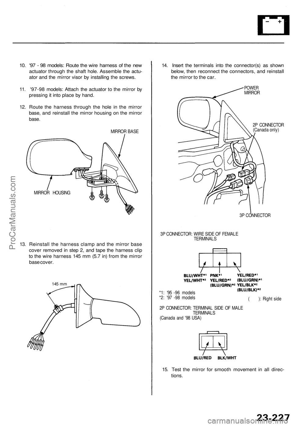
10. '97 - 98 models: Route the wire harness of the new
actuator through the shaft hole. Assemble the actu-
ator and the mirror visor by installing the screws.
11. '97-98 models: Attach the actuator to the mirror by
pressing it into place by hand.
12. Route the harness through the hole in the mirror
base, and reinstall the mirror housing on the mirror
base.
MIRROR BASE
MIRROR HOUSING
13. Reinstall the harness clamp and the mirror base
cover removed in step 2, and tape the harness clip
to the wire harness 145 mm (5.7 in) from the mirror
base cover.
145 mm
14. Insert the terminals into the connector(s) as shown
below, then reconnect the connectors, and reinstall
the mirror to the car.
POWER
MIRROR
2P CONNECTOR
(Canada only)
3P CONNECTOR
3P CONNECTOR: WIRE SIDE OF FEMALE
TERMINALS
*1: '95 -96 models
*2: '97 -98 models
2P CONNECTOR: TERMINAL SIDE OF MALE
TERMINALS
(Canada and '98 USA)
( ): Right side
15. Test the mirror for smooth movement in all direc-
tions.ProCarManuals.com
Page 1695 of 1771
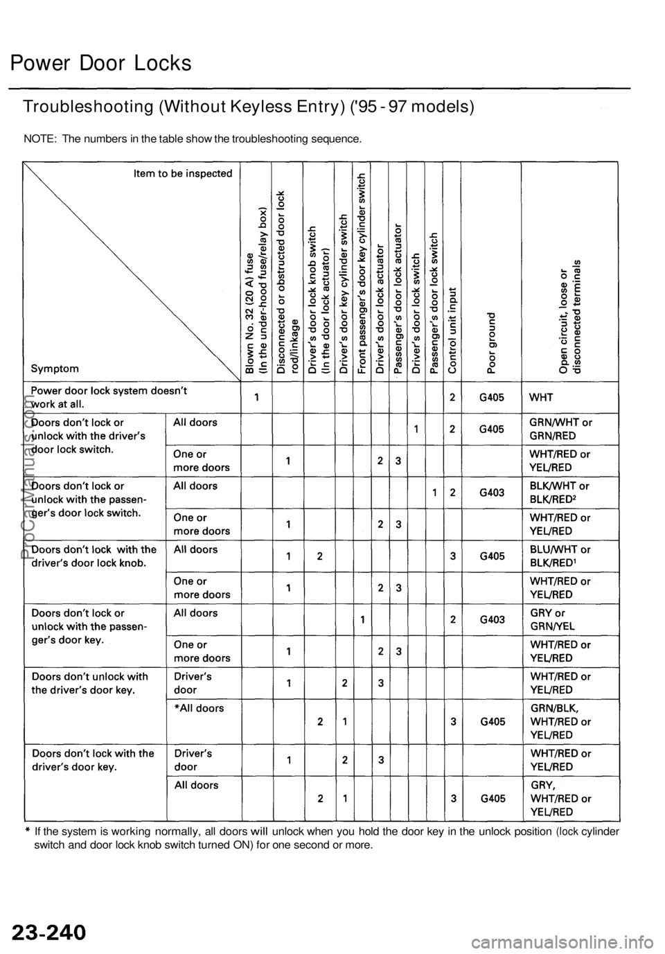
Power Doo r Lock s
Troubleshootin g (Withou t Keyles s Entry ) ('9 5 - 9 7 models )
NOTE: Th e number s in th e tabl e sho w th e troubleshootin g sequence .
I f th e syste m is workin g
normally , all door s will unloc k whe n yo u hol d th e doo r ke y i n th e unloc k positio n (lock cylinde r
switc h an d doo r loc k kno b switc h turne d ON ) fo r on e secon d o r more .
ProCarManuals.com