Page 798 of 1771
Pistons
Installation
Before installing the piston, apply a coat of
engine oil to the ring grooves and cylinder
bores.
1. If the crankshaft is already installed:
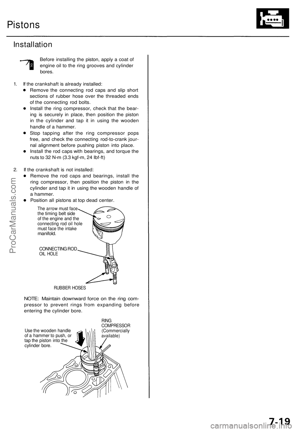
Remove the connecting rod caps and slip short
sections of rubber hose over the threaded ends
of the connecting rod bolts.
Install the ring compressor, check that the bear-
ing is securely in place, then position the piston
in the cylinder and tap it in using the wooden
handle of a hammer.
Stop tapping after the ring compressor pops
free, and check the connecting rod-to-crank jour-
nal alignment before pushing piston into place.
Install the rod caps with bearings, and torque the
nuts to 32 N-m (3.3 kgf-m, 24 Ibf-ft)
2. If the crankshaft is not installed:
Remove the rod caps and bearings, install the
ring compressor, then position the piston in the
cylinder and tap it in using the wooden handle of
a hammer.
Position all pistons at top dead center.
The arrow must face
the timing belt side
of the engine and the
connecting rod oil hole
must face the intake
manifold.
CONNECTING ROD
OIL HOLE
RUBBER HOSES
NOTE: Maintain downward force on the ring com-
pressor to prevent rings from expanding before
entering the cylinder bore.
Use the wooden handle
of a hammer to push, or
tap the piston into the
cylinder bore.
RING
COMPRESSOR
(Commercially
available)ProCarManuals.com
Page 805 of 1771
Engine Oil
Inspection
1. Check engine oil level with the engine off and the car
parked on level ground.
2. Make certain that the oil level indicated on the dip-
stick is between the upper and lower marks.
3. If the level has dropped close to the lower mark, add
oil until it reaches the upper mark.
CAUTION: Insert the dipstick carefully to avoid
bending it.ProCarManuals.com
Page 807 of 1771
The numbers in the middle of the API Service label tell
you the oil's SAE viscosity or weight. Select the oil for
your car according to this chart:
An oil with a viscosity of 5W - 30 is preferred for
improved fuel economy and year-round protection in the
car. You may use a 10W - 30 oil if the climate in your area
is limited to the temperature range shown on the chart.
4. Fill the engine with oil up to the specified level, run
the engine for more than three minutes, then check
for oil leakage.ProCarManuals.com
Page 810 of 1771
Oil Pressur e
Testing
If th e oi l pressur e warnin g ligh t stay s o n wit h th e engin e
running , chec k th e engine oil level . I f th e oi l leve l i s cor -
rect :
1 . Connec t a tachometer .
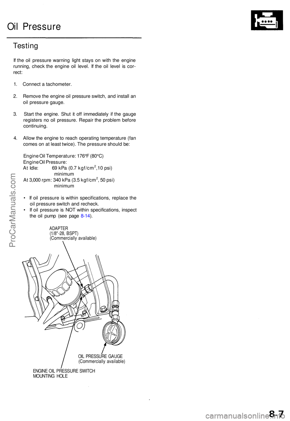
2 . Remov e th e engin e oi l pressur e switch , an d instal l a n
oi l pressur e gauge .
3 . Star t th e engine . Shu t i t of f immediatel y i f th e gaug e
register s n o oi l pressure . Repai r th e proble m befor e
continuing .
4. Allo w th e engin e to reac h operatin g temperatur e (fa n
come s o n a t leas t twice) . Th e pressur e shoul d be :
Engin e Oi l Temperature : 176° F (80°C )
Engin e Oi l Pressure :
A t Idle : 6 9 kP a (0. 7 kgf/cm
2,1 0 psi )
minimu m
A t 3,00 0 rpm : 34 0 kP a (3. 5 kgf/cm
2, 5 0 psi )
minimu m
• I f oi l pressur e i s withi n specifications , replac e th e
oi l pressur e switc h an d recheck .
• I f oi l pressur e is NO T withi n specifications , inspec t
th e oi l pum p (se e pag e 8-14 ).
ADAPTE R(1/8"-28, BSPT )(Commerciall y available )
OIL PRESSUR E GAUG E(Commerciall y available )
ENGINE OI L PRESSUR E SWITC HMOUNTIN G HOL E
ProCarManuals.com
Page 879 of 1771
PGM-FI System
Engine Control Module (ECM)
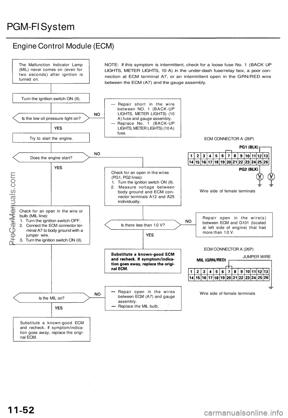
Is the low oil pressure light on?
Try to start the engine.
Does the engine start?
Check for an open in the wire or
bulb (MIL line):
1. Turn the ignition switch OFF.
2. Connect the ECM connector ter-
minal A7 to body ground with a
jumper wire.
3. Turn the ignition switch ON (II).
NOTE: If this symptom is intermittent, check for a loose fuse No. 1 (BACK UP
LIGHTS, METER LIGHTS, 10 A) in the under-dash fuse/relay box, a poor con-
nection at ECM terminal A7, or an intermittent open in the GRN/RED wire
between the ECM (A7) and the gauge assembly.
Is the MIL on?
Substitute a known-good ECM
and recheck. If symptom/indica-
tion goes away, replace the origi-
nal
ECM.
— Repair short in the wire
between NO. 1 (BACK-UP
LIGHTS, METER LIGHTS) (10
A) fuse and gauge assembly.
— Replace No. 1 (BACK-UP
LIGHTS, METER LIGHTS) (10 A)
fuse.
Check for an open in the wires
(PG1, PG2 lines):
1. Turn the ignition switch ON (II).
2. Measure voltage between
body ground and ECM con-
nector terminals A12 and A25
individually.
Is there less than 1.0 V?
Repair open in the wires
between ECM (A7) and gauge
assembly.
Replace the MIL bulb.
ECM CONNECTOR A (26P)
Wire side of female terminals
Repair open in the wire(s)
between ECM and G101 (located
at left side of engine) that had
more than 1.0 V.
ECM CONNECTOR A (26P)
Wire side of female terminals
The Malfunction Indicator Lamp
(MIL) never comes on (even for
two seconds) after ignition is
turned on.
Turn the ignition switch ON (II).
JUMPER WIREProCarManuals.com
Page 901 of 1771
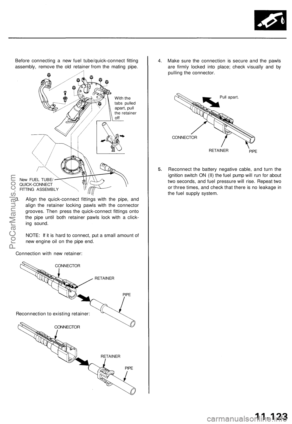
Before connecting a new fuel tube/quick-connect fitting
assembly, remove the old retainer from the mating pipe.
With the
tabs pulled
apart, pull
the retainer
off
New FUEL TUBE/
QUICK-CONNECT
FITTING ASSEMBLY
3. Align the quick-connect fittings with the pipe, and
align the retainer locking pawls with the connector
grooves. Then press the quick-connect fittings onto
the pipe until both retainer pawls lock with a click-
ing sound.
NOTE: If it is hard to connect, put a small amount of
new engine oil on the pipe end.
Connection with new retainer:
CONNECTOR
RETAINER
PIPE
CONNECTOR
RETAINER
PIPE
4. Make sure the connection is secure and the pawls
are firmly locked into place; check visually and by
pulling the connector.
Pull apart.
CONNECTOR
RETAINER
PIPE
Reconnect the battery negative cable, and turn the
ignition switch ON (II) the fuel pump will run for about
two seconds, and fuel pressure will rise. Repeat two
or three times, and check that there is no leakage in
the fuel supply system.
Reconnection to existing retainer:ProCarManuals.com
Page 1185 of 1771
8. Remov e th e circlip , the n remov e th e driv e shaf t
assembl y fro m th e pum p housin g usin g a plasti c
hammer .
9 . Remov e th e sea l space r an d oi l seal .
10 . Inspec t th e pum p housin g fo r damag e o n th e seal -
in g surfaces .
CIRCLIP38 m m
DRIV E SHAF TCheck fo r bend ,damag e an d wear .
PUMP SEA LSPACE R
OIL SEA LReplace .
PUMP HOUSIN G
11. Inspec t th e bearin g b y rotatin g th e oute r rac e slow -
ly . I f an y pla y o r roughnes s i s felt , replac e th e bear -
ing.
12. Remov e an d discar d th e bearin g usin g th e specia l
too l an d a press .
Press
HUB DIS/ASSEMBL Y BAS E07GA F-SD4070 0
13. Instal l th e ne w bearin g usin g th e specia l too l an d a
press .
Press
Instal l wit h th ered shielde d sid efacin g down .
HUB DIS/ASSEMBL Y BAS E07GAF-SD4070 0NOTE: Suppor t th e inne r rac ewith th e too l securely .
ProCarManuals.com
Page 1291 of 1771
Pump motor control:
The ABS control unit monitors the brake fluid pressure in the accumulator by the pressure switch ON/OFF signals. The
ABS control unit turns the pump on when the pressure in the accumulator drops, and stops the pump when the pressure
rises to the specified value.
If the pressure does not reach the specified value after the motor has operated continuously for a specified period, the
ABS control unit stops the motor and activates the ABS indicator light.
Self-diagnosis function:
The self-diagnosis function, provided in the sub-function of the ABS control unit, monitors the main system functions by
constantly transmitting the data between the two Central Processing Units (CPUs). When an abnormality is detected, the
ABS control unit turns the ABS indicator light on and stops the ABS, although the basic brake system continues to operate
normally.
When the ABS control unit detects an abnormality with the ABS and turns the ABS indicator light on, the diagnostic trou-
ble code (DTC), which shows the problem part or unit, is recorded in the control unit. The DTC can be read by the blinking
frequency of the ABS indicator light.
Fail-safe function:
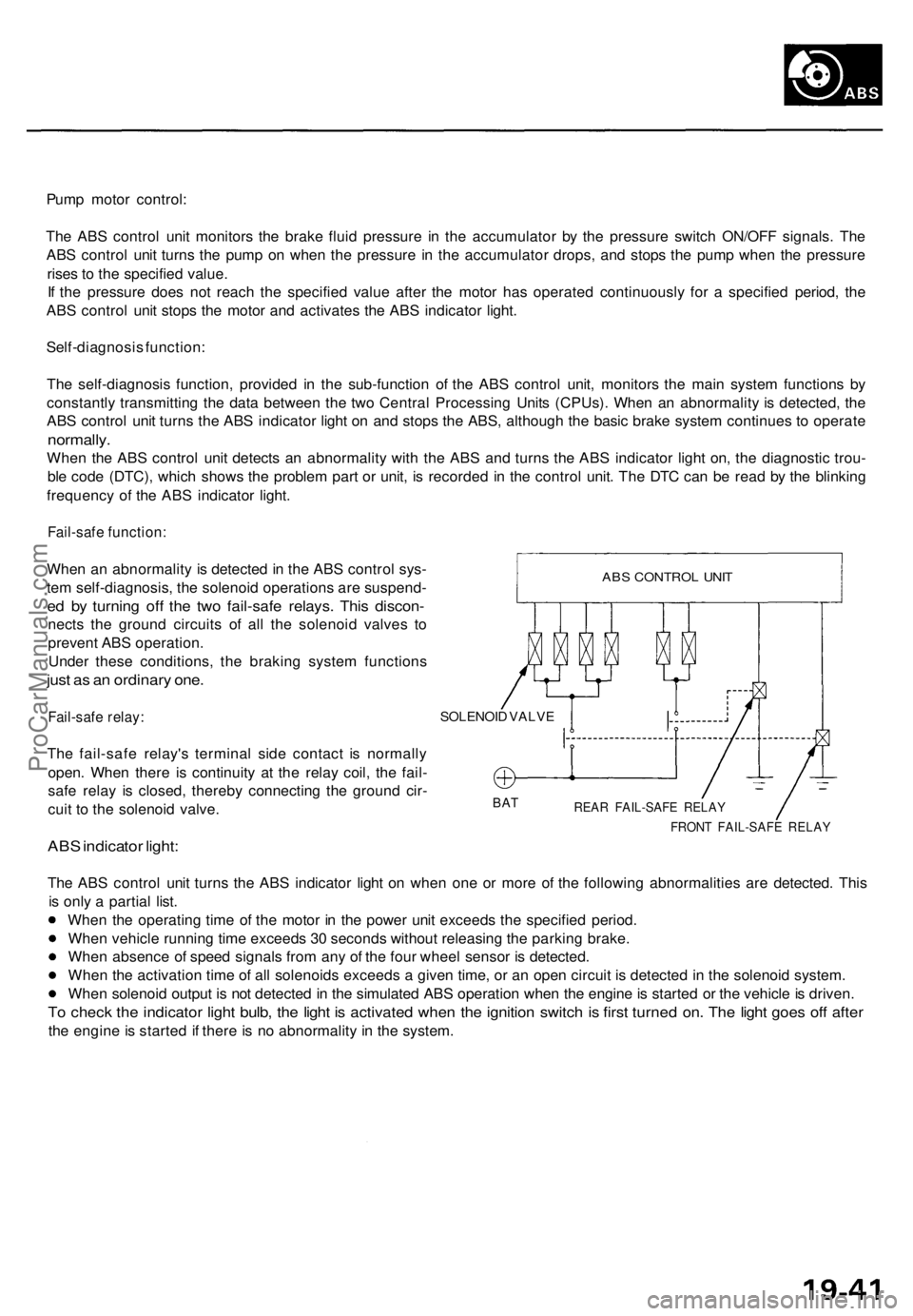
When an abnormality is detected in the ABS control sys-
tem self-diagnosis, the solenoid operations are suspend-
ed by turning off the two fail-safe relays. This discon-
nects the ground circuits of all the solenoid valves to
prevent ABS operation.
Under these conditions, the braking system functions
just as an ordinary one.
Fail-safe relay:
The fail-safe relay's terminal side contact is normally
open. When there is continuity at the relay coil, the fail-
safe relay is closed, thereby connecting the ground cir-
cuit to the solenoid valve.
ABS indicator light:
SOLENOID VALVE
BAT
REAR FAIL-SAFE RELAY
FRONT FAIL-SAFE RELAY
The ABS control unit turns the ABS indicator light on when one or more of the following abnormalities are detected. This
is only a partial list.
When the operating time of the motor in the power unit exceeds the specified period.
When vehicle running time exceeds 30 seconds without releasing the parking brake.
When absence of speed signals from any of the four wheel sensor is detected.
When the activation time of all solenoids exceeds a given time, or an open circuit is detected in the solenoid system.
When solenoid output is not detected in the simulated ABS operation when the engine is started or the vehicle is driven.
To check the indicator light bulb, the light is activated when the ignition switch is first turned on. The light goes off after
the engine is started if there is no abnormality in the system.
ABS CONTROL UNITProCarManuals.com